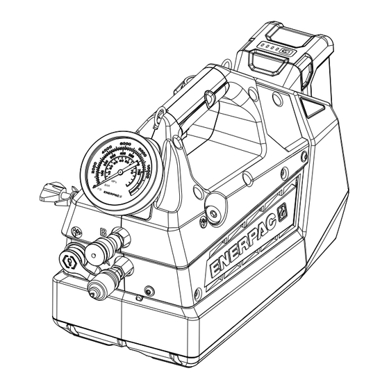
Page 1
Operation and Maintenance Manual XC2 Series Cordless Hydraulic Bolting Pumps Models XC2502B and XC2504B Document Number: L4589 Document Revision: E Issue Date: January 2024 Language: English To reduce the risk of injury, user must read and understand this document before use.
Page 2
XXX kg | XXX lbs AAXXXXXXXXXX Assembled in the USA Note: A typical XC2 Series nameplate is shown above. Nameplate data will vary depending on pump model and configuration. AVAILABLE LANGUAGES An electronic copy of this document is available online in multiple languages: •...
All hoses, fittings and couplers used force hydraulic tools is required prior to the operation of with the pump must be rated at 10,150 psi [700 bar] the pump. If training is needed, contact your local Enerpac minimum. distributor or authorized service center for information •...
Page 5
• Follow and understand all safety information • Use the Enerpac XC2 Series pump only with the contained in the torque wrench operation manual specified Enerpac 54 volt Li-Ion battery. Use of any and in any other documentation provided by the other battery may create a risk of injury and fire.
Other symbols may be informational only. Understand the meaning of each symbol before using the pump. Enerpac declares that the model XC2502B and XC2504B Selected symbols are shown in the following chart: cordless hydraulic pumps have been tested and conform...
XC2504B Torque 2-Position Wrenches * Hydraulic port thread size. Enerpac Spin-On hydraulic couplers are included with pump. ** At 85% relative humidity. *** Typical. Sound level will vary depending on pump speed and load. 3.2 Pressure and Flow Maximum Hydraulic Flow Rate (also see Section 3.3)
Page 8
Pendant Extension Cord, 10 ft [3 m] CC010 XC2502B XC2504B Shoulder Strap, XC2 Series Pumps SSTRP55 Note: Refer to Enerpac website or catalog for a complete description of available pump accessories. 3.7 External Dimensions Dimension Models XC2502B & XC2504B Item inch 20.5...
16. Battery Charger 17. Remote Pendant Item may be included with pump or may need to be purchased sepa- rately. Refer to Enerpac website or catalog for ordering information. Optional Accessory Figure 1: Features & Components, Models XC2502B and XC2504B...
The pump is equipped with Enerpac Spin-On coupler halves pre-installed in the pump “A” and “B” The Enerpac XC2 Series cordless torque wrench pumps combine the performance of a powered pump with the ports. Couplers must be polarized as shown in Figure 2 portability of a hand operated pump.
6.1 Charge Level Indicator NOTICE If using threaded hydraulic fittings instead A small panel containing a charge indicator button and quick-disconnect four charge indicator lights is located on the battery couplers, be sure that all housing. Press the button to display the battery charge connections are securely level.
To ensure compatibility and proper operation, use pump housing near the battery. Refer to Figure 8. only the specified Enerpac 54V Lithium-Ion battery with Depressing the top half of the power switch ( ❙ ) connects the pump.
Page 13
Before operating the pump under load, perform the air removal procedure to purge any trapped air from the system. Refer to Section 7.10. Set relief valve pressure to the setting that corresponds to the desired target torque for your application. Refer to instructions in Section 7.3. 7.3 Relief Valve Pressure (torque) Adjustment The pump contains a user-adjustable hydraulic pressure...
Page 14
Press and hold the pendant ON-ADVANCE button • Avoid making sudden start-stop movements to start the motor and build pressure. (“shock loading”) during bolting procedures. Failure to observe this precaution may cause a catastrophic With the motor running, check the pump pressure failure of the wrench to occur, and wrench gauge reading to determine the current relief valve components under high tension could become...
Page 15
WARNING In the following step, the pump motor will start and the valve will shift automatically, advancing the torque wrench. Verify that torque wrench is positioned to avoid injury or equipment damage before starting motor. To start the motor and advance the torque wrench, firmly grasp the carrying handle and pull the trigger switch fully upward.
Damage to the pump and/or hoses may result. NOTICE If the motor still fails to start, take the pump to an Enerpac authorized service center for inspection and 8.0 MAINTENANCE diagnosis. 7.10 Air Removal 8.1 Check Oil Level...
Page 17
Add oil as described in the following steps: Check oil for contamination by comparing the color of the oil in the reservoir fill tube to new unused Enerpac HF oil. With the power switch turned on ( ❙ ) , press the Unused Enerpac HF oil is a crisp blue color.
Use a suitable soft brush. Remove the oil fill plug and fill the reservoir with new Enerpac oil. Refer to Section 8.2 for hydraulic WARNING To avoid a shock hazard, do not insert any oil requirements and Section 8.3 for detailed oil fill...
• To prevent accidental start-up of pump during servicing, always remove battery from pump before performing any repair procedures. The Enerpac Connect App is available for download on the Apple App Store and on Google Play. Google Play and the Google Play logo are trademarks of Google LLC.
Page 20
If pump starts and operates normally, repair or replace the pendant. h. Motor and/or electronic Contact Enerpac authorized service center. control board damaged. i. Pump jammed due to Contact Enerpac authorized service center. obstruction. Possible internal damage to pump.
Page 21
Then, run the pump in retract mode while gently rocking the pump from side-to-side. b. Bypass valve malfunction. Contact Enerpac authorized service center. c. Oil intake screen clogged Contact Enerpac authorized service center. with debris.
Page 22
Refer to Section 2.2 of this manual for additional information. b. Mechanical or electrical Contact Enerpac authorized service center. component failure. 8. Pump does not build User-adjustable relief valve Adjust relief valve pressure. Refer to procedure pressure.
14.0 REPAIR PARTS SECTION CONTENTS PAGE FIGURE 15: MAIN ASSEMBLY ......................... 24 FIGURE 16: SHROUD HALVES & PENDANT ....................26 FIGURE 17: RIGHT-HAND SHROUD COMPONENTS ..................28 FIGURE 18: PUMP BASE ASSEMBLY ......................30 FIGURE 19: POWER UNIT & RESERVOIR ASSEMBLY .................. 32 FIGURE 20: POWER UNIT &...
Page 24
Figure 15: Main Assembly XC2502B Only Notes: Torque to 18-26 in-lbs [2 - 3 Nm]. Secure with Loctite 243 thread locking compound. Refer to manufacturer’s technical data sheet for application instructions. Apply PTFE tape. Torque to 10-12 ft-lbs [13.6 - 16.3 Nm]. Secure motor and battery wires with cable ties.
Page 25
Parts List for Figure 15 Part Number Item Description Model XC2502B Model XC2504B Screw, SHCS Hex, M5 CBZ517028-1A CBZ517028-1A Pin, 6 mm x 45 mm Lg DD3417059 DD3417059 Cable Tie, Screw Mount DD7326217 DD7326217 Gauge, Hydraulic Pressure DD7397223SR DD7397223SR Grommet...
Page 26
Figure 16: Shroud Halves & Pendant Notes: Torque to 18-26 in-lbs [2 - 3 Nm]. Secure with Loctite 243 thread locking compound. Refer to manufacturer’s technical data sheet for application instructions. Torque to 25-30 in-lbs [2.8 - 3.4 Nm]. Item 16 is supplied with all XC2500 Series pumps as standard equipment. L4589_e...
Page 27
Parts List for Figure 16 Part Number Item Description Model XC2502B Model XC2504B Plug, Soc Hd St Thread 0.750-16 B1006006 B1006006 Screw, SHCS Hex, M5 CBZ517028-1A CBZ517028-1A Washer, Flat CAE1050108-1A CAE1050108-1A Ring, Round DD4769667 DD4769667 Shroud, Left-Hand DD7920424 DD7920424 ...
Page 28
Figure 17: Right-Hand Shroud Components Circuit App Board Connections Pendant Trigger Connector Cable Notes: Torque to 120-144 in-lb [13.6 - 16.3 Nm]. Torque to 60-80 in-lb [6.8 - 9.0 Nm]. Torque to 8-10 in-lb [0.9 - 1.1 Nm]. Secure with Loctite 271 thread locking compound. Refer to manufacturer’s technical data sheet for application instructions.
Page 29
Parts List for Figure 17 Item Description Part Number Screw, M4 x 10 Thrd FRM DD3883028 Trigger, Variable Speed DD7874372 ✬ Shroud, Right-Hand DD7921424 Retainer, XC2 Oil Fill DD7926160 ✫ Circuit App Board DD7929827 Tube, Oil Vent DD7962268 ...
Page 30
Figure 18: Pump Base Assembly Notes: Torque to 18-26 in-lb [2.0 - 3.0 Nm]. Torque to 10-12 in-lb [1.13 - 1.36 Nm]. Pull wires for switch through hole in housing. Pull wires through hole in housing. L4589_e...
Page 31
Parts List for Figure 18 Item Description Part Number Screw, Flat Hd M5 CBA517028-1B Plate, Battery Interface w/Cable DD7953101 Bracket, Motor, XC2 DD8251111 Screw, M5 x 10, Thread Forming,Torx DD8781028 Base, XC2 Pump DD8836005 Switch, Rocker DPST 30 VDC 10A DD8866372SR Items included in 54V Battery Guide Kit, XC2BGK.
Page 32
Figure 19: Power Unit & Reservoir Assembly Notes: Torque to 45-60 in-lbs [5.1 - 6.8 Nm]. Attach magnet (item 9) to pump element Torque to 12-15 ft-lbs [16.3 - 20.3 Nm]. (item 23) prior to assembling bladder (item Torque to 55-65 in-lbs [6.2 - 7.3 Nm]. 27).
Page 33
Parts List for Figure 19 and Figure 20 Part Number Item Description Model XC2502B Model XC2504B Ball Cap A8038570 A8038570 Spring, Compression A8126110 A8126110 Ball, 0.125, Stl B1003016 B1003016 O-Ring, Round, 0.219, 0.344, 0.063 B1004503 B1004503 ★ O-Ring, Round, 0.250, 0.375, 0.063 B1005503 B1005503...
Page 34
Figure 20: Power Unit & Reservoir Assembly (repeated view) Notes: Torque to 45-60 in-lbs [5.1 - 6.8 Nm]. Attach magnet (item 9) to pump element Torque to 12-15 ft-lbs [16.3 - 20.3 Nm]. (item 23) prior to assembling bladder (item Torque to 55-65 in-lbs [6.2 - 7.3 Nm].
Page 35
Parts Kits for Figure 19 and Figure 20 Kit Symbol Description Items included in XC2 2L Bladder Kit, XC2B2LK. Items included in XC2 4L Bladder Kit, XC2B4LK. Items included in XCTW Pump Seal Kit, XC3SK. ★ Items included in Service Kit, XA1UARVK. ...
Page 36
Figure 21: Control Valve Assembly, View 1 of 2 Notes: Lubricate with oil prior to assembly. Press fit, 825-875 psi [56.8 - 60.3 bar] on a 10 ton press. Torque to 55-65 in-lbs [6.21 - 7.34 Nm]. Torque to 49-59 ft-lbs [66.5 - 79.9 Nm]. Torque to 120-144 in-lbs [13.56 - 16.27 Nm].
Page 37
Parts List for Figure 21 Item Description Part Number Cartridge Relief Valve 45423SR Back up Ring, Split, 0.094, 0.219, 0.045 B1005564 ✱ Copper Gasket C846037 ✱ PTF-SAE Flush Plug 0.062 DC6792245 Piston, B-Side Pilot DD4790051 ✱ Solenoid Valve, 3-Way, 2-Position, Electric DD5655660SR Shuttle Valve Cartridge Assembly DD6005900...
Page 38
Figure 22: Control Valve Assembly, View 2 of 2 10 11 Notes: Press fit, 825-875 psi [56.8 - 60.3 bar] on a 10 ton press. Coin, 275-325 psi [6.2 - 7.3 bar] on a 10 ton press. Torque to 55-65 in-lbs [6.21 - 7.34 Nm]. B-Side relief valve set to 2,600 +/- 100 psi [180 +/- 7 bar].
Page 39
Parts List for Figure 22 Item Description Part Number Seat A8015290 Spring A8038110 ✱ ● Ball, 0.188 Stl B1005016 ✱ ● Hex Jam Nut B1006124 ✱ ● O-Ring, Round, 0.219, 0.344, 0.063 B1009803 ✱ ✲ Set Screw, Flat Point BF3808027F ✱ ● Dust Cap, Metal, Female DC6629020 Ball Guide DD6573013...
Page 40
Figure 23: Eccentric Shaft & Housing Subassembly Notes: Position grey coated side of bushing (item 5) toward eccentric (item 3). Spin test after assembly (1 full eccentric rotation). Use a pick to align the gears with the ring gear. L4589_e...
Page 41
Parts List for Figure 23 Item Description Part Number Ring Gear DC7089228 Bearing DC7096155 Assembly, Eccentric Shaft (See Figure 24) Key, Ring Gear DC7452251 Bushing DC7464108 Eccentric Housing DD8425001 Items included in Eccentric Housing Service Kit, XC2ECK. ...
Page 42
Figure 24: Eccentric Shaft Assembly Sectional View Note: Position grey coated side of thrust washer (item 4) toward lip seal (item 1). Figure 25: Pump Element L4589_e...
Page 43
Parts List for Figure 24 Item Description Part Number Lip Seal DC7090476 Eccentric, 4mm DC7117537 Subassembly, Eccentric Shaft DC7870950 Washer, Thrust DC7186108 DC7191251 Spring, Wave DC7750410 Subassembly, Cam DC7755950 Items included in Eccentric Housing Service Kit, XC2ECK. ...
Page 44
Figure 26: Pump Element Components 0.59 - 0.63 inch [15.0 - 15.9 mm] Notes: Torque to 9.6-11.8 ft-lb [13 - 16 Nm]. Torque to 44.3-52.3 ft-lb [60 - 71 Nm]. Torque to 18.5-22.1 ft-lb [25 - 30 Nm]. Adjust length of bypass end cap (item 18) to between 0.59-0.63 inch [15.0 - 15.9 mm] from spot face.
Page 45
Parts List for Figure 26 Item Description Part Number Plug, Flush, Hex 27.0 Stl Teflon A1006245 ✦ Ball Cap A8038570 ✦ Spring, Compression A8126110 ✦ Ball, 0.125 Stl B1003016 ✦ Ball 0.188 Stl B1005016 ✦ Back Up Ring, Split B1006564 ★ ✦...
Page 46
• Charger must be purchased separately if not included in the shipment with the battery or tool. Unit is auto-voltage sensing, 100-240 VAC, 50/60 Hz. • North America, Europe and Australia: Charger and power cord includes one Enerpac EC1F54 battery charger and the AC power cord for use in the selected region. Charger not sold without power cord.
Page 47
Battery Charger & Power Cord, European Union - 230V EC1F542E Power Cord, Japan - 100V ECC541N Power Cord, United Kingdom - 240V ECC542U Parts List for Figure 28 Item Description Part Number Shoulder Strap, XC2 Series Pumps SSTRP55 Pendant Extension Cord, 10 ft [3 m] CC010 L4589_e...
Page 48
Figure 29: Hydraulic Schematic RETRACT ADVANCE PORT PORT RELIEF VALVE (B SIDE) GAUGE B-SIDE SHUTTLE VALVE PISTON 4 WAY, 2-POSITION DIRECTIONAL CONTROL VALVE 24VDC (ELECTRIC SOLENOID OPERATED) CHECK VALVE USER-ADJUSTABLE RELIEF VALVE Note: Pump internal safety relief valve set at 10,400- 10,800 psi [717 - 744 bar].
Need help?
Do you have a question about the XC2 Series and is the answer not in the manual?
Questions and answers