
Related Manuals for HULALA HOME CBLS1047


Summary of Contents for HULALA HOME CBLS1047
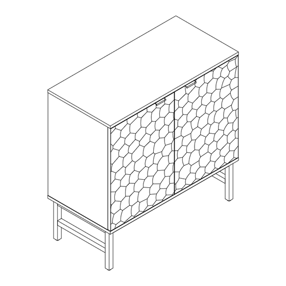
- Page 1 HULALA ITEM NO.CBLS1047 NOTE: This brochure contains IMPORTANT safty info. Please read and keep for future reference. 01/23...
- Page 2 MAINTAINANCE AND WARNING 1.Keep furniture away from heat sources. 2.Do not clean furniture with harsh cleaner or polishes.Do not use detergents,solvents,abrasives,spray packs or leather cleaner. Use non-color mild soap with warm water to clean spills(Mix 1:10 soap to water). 3.Do not place furniture under direct sunlight,material will possibly fade over time.
-
Page 3: Explosive View
EXPLOSIVE VIEW 2PERSONEN 03/23... -
Page 4: Parts List
PARTS LIST 04/23... -
Page 5: Hardware List
HARDWARE LIST Ø6*50mm Ø6*35mm Ø6*12mm Ø8*30mm Ø3.5*14mm TOOL LIST HARDWARE SPARE LIST Ø6*35mm Ø8*30mm Ø6*50mm 05/23... - Page 6 HARDWARE SPARE LIST Ø6*12mm Ø3.5*14mm 06/23...
- Page 7 ASSEMBLY INSTRUCTIONS STEP-1 1.Prepare for part A. Align the holes in part A, insert wooden dowel #7 by hand, tighten with screwdriver #16 tighten #3。 8*30mm 07/23...
- Page 8 ASSEMBLY INSTRUCTIONS STEP-2 Connect the part A with part C&D&E. align the hole in the part C&D&E ,insert the bolt #3 and wooden dowel #7 in part A into part C&D&E. insert cam bolt #4 into the corresponding hole of side panel C&D&E,and tighten the nuts #4 with a screwdriver #16.
- Page 9 ASSEMBLY INSTRUCTIONS STEP-3 Manually insert #7 wooden dowels (C&D&E), slide in the part G into the groove in part D,E and C,E . make sure they are also in groove in part A. C&D 8*30mm 09/23...
- Page 10 ASSEMBLY INSTRUCTIONS #2 to attach Magnetic device #2 to bottom panel (B) , tighten bolts #2 with screwdriver #16. 10/23...
- Page 11 ASSEMBLY INSTRUCTIONS STEP-5 Connect the part B the pre-assembled unit in step 5. Then align the holes in part B,Insert screw #8 and push it down so that it connects to parts C&D&E. Next,and tighten the screw #8 with an Allen key #17.
- Page 12 ASSEMBLY INSTRUCTIONS w 12 to connect the J&K,and tighten the screw #12 with an Allen key #17. K&L 12/23...
- Page 13 ASSEMBLY INSTRUCTIONS STEP-7 install leg (J&K) on of bottom panel (B), ensure the corresponding holes are aligned and fix with screw #9, then tighten the screw with an Allen key #17. 6*35mm 13/23...
- Page 14 ASSEMBLY INSTRUCTIONS STEP-8 Insert hardware #14 into part (G) as shown, screw in screw #13 using screwdriver #16 and tighten fully. 14/23...
- Page 15 ASSEMBLY INSTRUCTIONS STEP-9 1.Use screw #6 to attach hinge #6 to door (I&H) , tighten screw #6 with screwdriver #16. Use bolt #2 to attach Magnetic device #2 to door (I&H) , tighten bolts #2 with screwdriver #16. 15/23...
- Page 16 ASSEMBLY INSTRUCTIONS STEP-10 Use screw #6 to attach left door (I) and right door( H) to pre-assemble unit at step 9 ,tighten screw #6 with screwdriver #16 . 16/23...
Need help?
Do you have a question about the CBLS1047 and is the answer not in the manual?
Questions and answers