
Related Manuals for baxter TruLight 5000


Summary of Contents for baxter TruLight 5000
- Page 1 Instructions for use TruLight 5000 / 3000 Surgical light Read the instructions for use carefully before using AMERICAN ENGLISH the product and keep it safe for future reference. en-US...
- Page 2 This page is intentionally left blank.
- Page 3 +49 3671 586–0 Fax: +49 3671 586–41165 surgical@hillrom.com hillrom.com Baxter Medical Systems GmbH + Co. KG is a Baxter International Inc. company. The manufacturer is hereinafter referred to as Baxter. Technical Customer Service The contact details for the current Technical Customer Service hubs in the individual countries are listed on the Internet at www.hillrom.com.
- Page 4 TruLight 5000 / 3000 This page is intentionally left blank. 7990088_030_03 – 2080493 – 2023-01-19...
-
Page 5: Basic Information
© Baxter Medical Systems GmbH + Co. KG Reprinting, copying, or translating this document, in whole or in part, is forbidden without the express written permission of Baxter. All rights under copyright law are expressly reserved by Baxter. 7990088_030_03 – 2080493 – 2023-01-19... - Page 6 TruLight 5000 / 3000 This page is intentionally left blank. 7990088_030_03 – 2080493 – 2023-01-19...
-
Page 7: Table Of Contents
4.1.3 TruLight 5000/3000 Pendant surgical light system ....... . 24 4.1.4... - Page 8 Contents Selection of functions ............39 Attaching the handle adapter.
- Page 9 TruLight 5000 ........
- Page 10 Contents This page is intentionally left blank. 7990088_030_03 – 2080493 – 2023-01-19...
-
Page 11: Usage Specifications
Usage specifications Usage specifications Normal use The surgical light system can have up to four support arms with up to three lamp heads. In addition to the lamp heads, other products can also be attached using a spring arm (e.g. VidiaPort spring arm with monitor holder and monitor). -
Page 12: Ambient Conditions For Storage And Transport
Usage specifications Ambient conditions for storage and transport Temperature: -15 °C to +60 °C/ +5 °F to +140 °F Air humidity: 5% to 95% Atmospheric pressure: 50 kPa to 106 kPa/ 7 psi to 15 psi Fragile contents Keep dry Service life With normal use, the service life is 10 years. -
Page 13: Safety
Safety Safety Configuration The configuration of a surgical light with the listed products was tested by Baxter and subjected to a compliance assessment. – Various canopies – Various central axes with booms Spring arm Product designation Part number L21, 3P Springarm... -
Page 14: Combination With Other Products From Baxter
OPL Interface Converter 1793338 Combination with other products from Baxter Baxter offers a wide variety of products for further equipping of the surgical light. Not all products are available in all countries. Detailed information can be obtained from the relevant representative offices of Baxter, which are represented worldwide. -
Page 15: Combination With Products From Other Manufacturers
Baxter accepts no responsibility for the combination of the surgical light with third-party products. The guarantee/warranty for products from Baxter may become void in the event of their combination with third-party products. 7990088_030_03 – 2080493 – 2023-01-19... -
Page 16: Operator's Responsibility
Safety Operator's responsibility The operator is the natural or legal person who operates the product himself for commercial or economic purposes or who leaves its operation to a third party. The operator bears the legal product responsibility for protecting personnel or third parties. The medical device may only be operated and applied according to its intended purpose and the general rules of technology. -
Page 17: Information Notices
Safety Information notices 2.7.1 Safety instructions – The information notices on the product provide information about residual dangers during use, or provide additional useful information. – The device label and all information notices must be present and be undamaged in the prescribed locations on the product. A damaged, illegible or missing device label / information notice must be replaced immediately. - Page 18 – Data Matrix Code – (01) Global Trade Item Number (GTIN) – (11) Date of manufacture (Year Month Day) – (21) Serial number – (240) Part number Baxter part number Serial number Medical product The device conforms to Regulation 2017/745/EU concerning medical devices.
-
Page 19: Overview
TruLight 5000/3000 Mobile – mounted on a mobile frame Description TruLight 5000/3000 surgical lights are available in the Single, Duo, Trio, Quad, Wall, Mobile and Pendant variants, with different boom lengths and spring arms. The Single, Duo, Trio, Quad and Pendant variants are ceiling- mounted versions with support arms. -
Page 20: Overview Of Surgical Light
– two horizontally rotating and vertically adjustable light heads [13] In the example, the TruLight 5000/3000 Ceiling Trio surgical light system is equipped with the following additional accessories of Baxter and the following third-party products: –... - Page 21 Description – a Handle sleeve handle adapter [35] and a sterile disposable handle/cover for the Adaption disposable handle handle adapter [18] on the lamp head mount – a sterilizable handle [20] for the ALC Plus handle adapter [17] – a sterilizable handle [20] for the handle on the TruLight xx00 [34] lamp head –...
-
Page 22: Trulight 5000/3000 Ceiling Quad Surgical Light System
– the canopy [1] – the ceiling mount [2] (a part of Pre-Install Set TruLight 5000 / 3000) and the central axis [3] – a horizontally rotating upper C boom [4] on the central axis with a horizontally and vertically adjustable MD26+ [7] spring arm (VidiaPort Springarm Top) –... - Page 23 Description – a Handle sleeve handle adapter [35] and a sterile disposable handle/cover for the Adaption disposable handle handle adapter [18] on the lamp head mount – a sterilizable handle [20] for the ALC Plus handle adapter [17] – a sterilizable handle [20] for the handle on the TruLight xx00 [34] lamp head –...
-
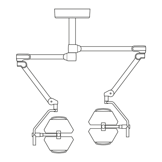
Page 24: Trulight 5000/3000 Pendant Surgical Light System
LCH19 spring arm [9] – a rotating and vertically adjustable light head [13] In the example, the TruLight 5000/3000 Pendant surgical light system is equipped with the following additional accessories of Baxter and the following third-party products: –... - Page 25 Description Canopy Central axis Low room height spring arm (LCH19) [11] Flat screen [12] Comfort strap [13] Lamp head [14] Control element The functions available on the control element depend on the functional scope of the surgical light. The functional scope of the control element on the light head may be somewhat limited compared to the control element on the wall control panel.
-
Page 26: Trulight 5000/3000 Wall Surgical Light System
LCH19 spring arm [9] – a rotating and vertically adjustable light head [13] In the example, the TruLight 5000/3000 Wall surgical light system is equipped with the following additional accessories of Baxter and the following third-party products: –... -
Page 27: Trulight 5000 / 3000 Mobile
Description 4.1.5 TruLight 5000 / 3000 Mobile The mobile surgical light can be moved freely in any direction, as all 4 wheels are able to turn on their own axes. Two wheels arranged diagonally on the stand foot can be braked. The parking brake allows the surgical light to be safely parked. -
Page 28: Overview Of Control Modules
Working distance indicator (3 steps from left to right: 80 cm / 31.50 inch, 100 cm / 39.37 inch, 120 cm / 47.24 inch) 4.2.2 Controls at the TruLight 5000 lamp head [i2] Switching the surgical light function on and off [i3]... -
Page 29: Controls At The Trulight 5000 Comfort Strap
The indicator lights up when the Endo lighting intensity is switched on. 4.2.3 Controls at the TruLight 5000 comfort strap The functions on the controls available for adjusting the lighting depend on the functional scope of the surgical light. The following overview is based on the maximum equipment level. -
Page 30: Wall Control Panel
The functional scope of the wall control panel corresponds to that of the controls on the surgical light. An exception to this is the Low Room Height version of the TruLight 5000 surgical light. Due to the design of the Low Room Height version, the controls on the lamp head have a more limited functional scope. -
Page 31: Handle Adapter
Description Handle adapter The Adaption disposable handle [A] handle adapter is used to hold adapters (products from third-party manufacturers) to which sterile disposable handles are attached. The Adaption Standard Handle [B] handle adapter is used to attach the Sterilizable Central Handle [C]. The Adaption disposable handle [A] and Adaption Standard handle [B] handle adapters can also be used to compensate for the weight on the mount of the light head, as well as a cover for the electrical... -
Page 32: Power Supply
Setting options 4.6.1 Light field size The light field size function is only available for the TruLight 5000 surgical light. The light field size concerns the diameter of the light field. At constant working distance, the user may decide between a narrow and a wide light field, depending on the size of the wound field. -
Page 33: Color Temperature
5000 K in steps of 500 K. 4.6.6 Synchronization The function is only available for the TruLight 5000 surgical light. During synchronization, the color temperature for the surgical light on which the function was selected is transferred to the other surgical lights. - Page 34 If the spring arm does not remain steadily in the selected height position, the spring force must be adjusted by staff trained in this work by Baxter. If the spring arm creeps upwards, the spring force is too high. If the spring arm creeps downwards, the spring force is too low.
-
Page 35: Illuminated Side Handles
Illuminated side handles The illuminated side handles on the lamp head are only available for the TruLight 5000 surgical light. The light system is available with the following options: – The side handle is permanently lit up (delivery state ex factory). - Page 36 Risk to the patient if the power supply fails • The power supply of the surgical light system may not be interrupted. Risk of charge balancing • To avoid electrostatic discharge between the metallic parts of the device and the body of the patient, the user may not touch the surgical light system and the patient at the same time.
- Page 37 Observe the instructions for use with the document number 7990089. • Only components and accessories authorized by Baxter may be used on the support arm system. Danger due to uncontrolled movement on the support arm system •...
-
Page 38: Inspections During Operation
Following any damage reported by a user, a functional check and a visual inspection must be carried out by personnel trained to perform these tasks by Baxter. Weekly inspection At least once a week, a functional check and a visual inspection must be carried out by personnel trained to perform these tasks by Baxter. -
Page 39: Selection Of Functions
Selection of functions The functions of the surgical light are set with the following control units: – Control element – ALC Plus handle adapter (Adaptive Light Control Plus) – Wall control panel – User interface of an external control unit (operating integration systems) The commands of the individual control modules are executed in the following sequence:... -
Page 40: Handle Sleeve Flange/Handle Sleeve Ring
5.4.2 Handle sleeve flange/Handle sleeve ring Attach the Adaption disposable handle handle adapter to the mount (see chapter 5.4.1). Push the Handle sleeve flange or Handle sleeve ring [35] handle adapters onto the Adaption disposable handle [18] handle adapter. Make sure that the plastic catch [A] on the Adaption disposable handle [18] handle adapter is correctly engaged in the securing hole [B] on the Handle sleeve [35] handle adapter. -
Page 41: Connecting The Power Supply
Connecting the power supply 5.6.1 Ceiling and wall-mounted versions: The power supply must be connected by specialized personnel with the necessary access authorization, knowledge and documentation to set up internal power supplies. When power is supplied, the surgical light is in standby-mode. 5.6.2 Mobile version WARNING... -
Page 42: Disconnecting The Power Supply
Disconnecting the power supply 5.7.1 Ceiling and wall-mounted versions: The surgical light must be disconnected from the power supply by specialist staff, with the necessary access rights, knowledge and documentation in regards to the institution’s power supply. Switch off the surgical light on a control unit. Switch off all products connected to the surgical light, such as the TruVidia HD camera. -
Page 43: Positioning The Surgical Light
5.10 Positioning the surgical light CAUTION Pinching hazard When swiveling the lamp head, do not place fingers between the cardan joint and the lamp head. • Only position the light head using the sterilizable handle or the non-sterile side handles. To prevent damage to the product, observe the following when positioning the surgical light: –... -
Page 44: Moving The Mobile Surgical Light
5.11 Moving the mobile surgical light Do not exert excessive force onto the spring arm or the lamp head in the braked state, as this may cause the surgical light to tilt. Do not attach any additional loads to the spring arm. Switch off the surgical light at a control module and disconnect it from the mains power (see Chapter 5.7). -
Page 45: Setting The Size Of The Light Field
Switching off the Endo lighting intensity: Controls on the surgical light or a wall control panel: – Press the [i4] button until the Endo [a6] status indicator goes off. The LED for the actually set lighting intensity [a1] lights up. 5.12.2 Setting the size of the light field Narrow light field:... -
Page 46: Adjusting The Alc (Adaptive Light Control)
5.12.4 Adjusting the ALC (Adaptive Light Control) The function is set on the controls or the wall control panel. Controls on the lamp head: Press the corresponding key [i8]. The status indicator next to the [i8] key lights up (near 80 cm / 31.50 inch [A], middle 100 cm / 39.37 inch [B], far 120 cm / 47.24 inch [C]). -
Page 47: Adjusting The Braking Force At The Boom And Spring Arm
5.13 Adjusting the braking force at the boom and spring arm The braking force should only be set by personnel who have been trained by Baxter in this work. 5.13.1 C boom There are 2 opposing brake screws on each boom. -
Page 48: S Boom
Install the right rear cover [E] on the boom [4]. a) Position the right rear cover on the boom so that the upper cover [H] is inside the rear cover. b) Attach the right rear cover at the top and bottom to the boom with a PT screw [F] (Torx T10 screwdriver). - Page 49 Remove the right rear cover [A] from the boom [4]. a) Using a Torx T10 screwdriver, remove the upper and lower PT screw [G] on the right rear cover. b) Remove the right rear cover from the boom. To adjust the brake force, alternately turn both opposite brake screws [H] by the same number of rotations with a Size 5 Allen key.
-
Page 50: Spring Arm
5.13.3 Spring arm There are 2 opposing brake screws on each boom. Switch off the surgical light at a control module and disconnect it from the mains power (see Chapter 5.7). Remove the decor caps [A] of the socket cover [B]. a) Lightly press in the right and left decor caps near the lugs [C] and pull the decor caps out of the openings [D]. -
Page 51: Setting The Spring Force Of The Spring Arm
Setting the spring force of the spring arm The spring force should only be set by personnel who have been trained by Baxter in this work. During adjustment work, make sure that any electrical cables in the spring arm are routed in the center of the spring arm and do not slip underneath other components. -
Page 52: Ac 2000 Nrh Mobile Spring Arm
Adjusting the swivel range of the control arm upwards and downwards The swivel range should only be set by personnel who have been trained by Baxter for this work. Adjust the swivel range in such a manner that collisions with the ceiling or other objects are ruled out. -
Page 53: Spring Arm Lch19
Mount the front cover [A] on the spring arm [8]. a) Rotate the recess of the segment lock [G] over the optional brake screw or the brake screw opening [H]. b) Position the right and left front spring arm covers on the spring arm so that, at the joint between the two front cover panels, all catches slide into one another and engage. -
Page 54: Ac 2000 Nrh Mobile Spring Arm
Mount the front cover on the spring arm [9]. a) Position the right front cover [D] on the spring arm so that there is a gap [I] between the connecting pin of the adaptation [H] and the cover. b) Attach the right front cover to the spring arm with 3 PT screws [E] (Torx T10 screwdriver). -
Page 55: Adjusting The Optional Brakes On The Spring Arm
5.16 Adjusting the optional brakes on the spring arm The braking force should only be set by personnel who have been trained by Baxter in this work. 5.16.1 Spring arm L21 Switch off the surgical light at a control module and disconnect it from the mains power (see Chapter 5.7). -
Page 56: Spring Arm Lch19
Move the spring arm upwards and downwards. Check the secure fit of the upper and lower faceplate while doing so. – The locking hooks must engage with the front spring arm cover. – The plates must slide easily in the lateral guides. 5.16.2 Spring arm LCH19 Switch off the surgical light at a control module and... -
Page 57: Ac 2000 Nrh Mobile Spring Arm
Mount the front cover on the spring arm [9]. a) Position the right front cover [D] on the spring arm so that there is a gap [K] between the connecting pin of the adaptation [J] and the cover. b) Attach the right front cover to the spring arm with 3 PT screws [E] (Torx T10 screwdriver). -
Page 58: Adjusting The Brake Force On The Surgical Light
5.17 Adjusting the brake force on the surgical light The braking force should only be set by personnel who have been trained by Baxter in this work. 5.17.1 Cardan joint Switch off the surgical light at a control module and disconnect it from the mains power (see Chapter 5.7). -
Page 59: Light Head With Alc Plus Function
5.17.3 Light head with ALC Plus function Switch off the surgical light at a control module and disconnect it from the mains power (see Chapter 5.7). Remove the sterilizable handle from the handle adapter. Remove the retaining ring [A] (4 Allen screws M4x15 mm/ M4x0.59 inch). -
Page 60: Decommissioning
5.18 Decommissioning WARNING Risk of infection The product may be contaminated with infectious substances. • The product must always be disinfected before temporarily or permanently taking it out of service. Disconnect the surgical light from all mains power supply terminals (see Chapter 5.7), and secure it against being switched on again when temporarily or permanently taking the surgical light out of service. -
Page 61: Cleaning And Disinfection
Cleaning and disinfection Cleaning and disinfection WARNING Risk of infection for the patient • No cleaning work may be carried out during operation. WARNING Danger of electric shock Contact with live parts may result in electric shock. • Take the surgical light out of service before cleaning and disinfecting it. -
Page 62: Wipe-Down Disinfection
Only agents or chemicals compatibility-tested and approved by Baxter may be used for cleaning and disinfecting. When using alternative cleaning agents and disinfectants, Baxter cannot confirm any material compatibility. Do not use agents that are not listed, otherwise functional components may be altered or damaged. -
Page 63: Recommended Disinfecting Agents
Moisten a cloth with cleaning agent or disinfectant. Clean the surgical light system with the damp but not wet cloth. Recommended disinfecting agents Baxter recommends the following disinfecting agents for manual use: Manufacturer Product designation B. Braun Melsungen AG... - Page 64 Cleaning and disinfection For surface disinfection of the support arm system (ceiling mount, central axis, extension arm and spring arm), the following disinfectants are permitted: Preparation Active ingredient Meliseptol Alcohols/Aldehyde Ethanol 60% Alcohols Chlorhexidine 0.5% in 70% Chlorbasis Ethanol Chlorine 250 ppm in 1 liter Chlorbasis distilled water Haemosol 1% in 1 liter water...
-
Page 65: Troubleshooting
Troubleshooting Troubleshooting If an error recurs or cannot be resolved, take the device out of service and inform the Technical Customer Service of Baxter. Error Possible cause Correction Support arms The lamp head moves down or rises. The spring force in the spring Adjust the spring force. -
Page 66: Maintenance
The products must be repaired only by qualified service technicians. The contact details of service technicians can be obtained from the Technical Customer Service at Baxter. After each repair, an electrical safety inspection according to the criteria specified by Baxter must be carried out. -
Page 67: Spare Parts
If you have any questions about proper disposal, please contact the Technical Customer Service at Baxter, your local dealer, or the appropriate national authority. In addition to regional disposal, faulty or obsolete products can be returned to Baxter. -
Page 68: Technical Data
Technical data Technical data 12.1 Device data IP classification according to IEC 60529 Lamp head IP20 Support arm system IP30 Operating mode Surgical light Continuous operation Dimensions TruLight x3x0 Height [A] 67 mm / 2.64 inch Height [B] 87 mm / 3.42 inch Width [C] 487 mm / 19.17 inch Width [D]... -
Page 69: Trulight 3000
Technical data 12.1.1 TruLight 3000 Product designation TruLight 3300 3500 3510 Equipment Adaptive Light Control (ALC) Sterile Light Control (SLC) – – – Adaptive Light Control Plus (ALC Plus) – – – TruVidia HD camera – – Side handles, illuminated –... -
Page 70: Trulight 5000
1332 cm² / 206.46 inch² 1892 cm² / 293.26 inch² Weight of the lamp head 13.6 kg / 29.98 lbs 16.4 kg / 36.16 lbs (including comfort and central strap) 12.1.2 TruLight 5000 Product designation TruLight 5300 5310 5320 5500... - Page 71 Technical data Electrical data TruLight 5300 53x0 5500 55x0 Average service life of the bulb > 60,000 hrs. > 60,000 hrs. > 60,000 hrs. > 60,000 hrs. (LED) Classification according to the Act on Medical Devices (MPG) Lighting data TruLight All light technology values 53x0 55x0...
-
Page 72: Support Arm System Swivel Ranges
Technical data Mechanical Data TruLight 5300 5310 5320 5500 5510 5520 Lamp head diameter 640 mm / 25.20 inch 730 mm / 28.74 inch Flow surface of the lamp head 2100 cm² / 325.50 inch² 3100 cm² / 480.50 inch² Light-emitting surface 1332 cm²... - Page 73 Vertical: > 360° (without stop) TruLight 3000 Type Comfort strap – Lamp head of Vertical: < 420° (with end stop) TruLight 5000 Lamp head – Cardan joint 200° (-100°/+100°) Ceiling-mounted version with LCH19 spring arm (Version: Low room height) Ceiling conduit - Boom Horizontal: >...
- Page 74 Vertical: > 360° (without stop) TruLight 3000 Type Comfort strap – Lamp head of Vertical: < 420° (with end stop) TruLight 5000 Lamp head – Cardan joint 200° (-100°/+100°) Wall-mounted version with LCH19 spring arm (Version: Low room height) Wall bearing - Boom...
- Page 75 Technical data Handle sleeve flange type middle handle adapter Diameter [A] 101.6 mm / 4.00 inch Length [B] 138.8 mm / 5.46 inches Handle sleeve flange type long handle adapter Diameter [A] 101.6 mm / 4.00 inch Length [B] 194.6 mm / 7.66 inches Handle sleeve ring type short handle adapter Diameter [A] 50.3 mm / 1.98 inch...
-
Page 76: Electromagnetic Compatibility
HF emissions in accordance with Class A The TruLight 5000 and the TruLight 3000 CISPR 11 system are intended for operation in facilities other than private homes, Harmonic emissions as per... - Page 77 Technical data Guidelines and manufacturer's declaration – electromagnetic immunity Guidelines and manufacturer's declaration – electromagnetic immunity The device has been designed for operation in one of the electromagnetic environments described below. The customer or user of the device should ensure that it is used in such an environment. The support arm system may not move unintentionally or cause interference.
- Page 78 Technical data Immunity testing IEC 60601-1 test level Compliance level Environment - guidelines Conducted HF in D=1.2√P accordance with 0.15 MHz – 80 MHz 0.15 MHz – 80 MHz IEC 61000-4-6 in the ISM band between in the ISM band between 0.15 MHz and 80 MHz 0.15 MHz and 80 MHz Radiated HF...
- Page 79 Technical data Test Band Service Modulation Max. Distance Immunity frequency (MHz) power level (MHz) (V/m) 800 – 960 GSM 800/900 Pulse modulation 18 Hz 2 TETRA 800 iDEN 820 CDMA 850 LTE band 5 1720 1700 – GSM 1.800 Pulse modulation 217 Hz 2 1990 CDMA 1900 1845...
-
Page 80: Svhc (Substance Of Very High Concern)
1907/2006, the following products may contain components with reportable substances in concentrations exceeding 0.1 mass percent. A list of affected components will be provided by Baxter on request. The list can also be seen on the Internet at ois.hillrom.com/ois. 7990088_030_03 – 2080493 – 2023-01-19... -
Page 81: Product Certification
Regulation 2017/745/EU concerning medical devices, and is compliant with the version of this regulation in force at the time of product sale. Baxter declares the conformity of the surgical light with the essential safety and performance requirements according to Regulation 2017/745/EU concerning medical devices, Annex I. - Page 82 Product certification This page is intentionally left blank. 7990088_030_03 – 2080493 – 2023-01-19...
- Page 83 This page is intentionally left blank.
- Page 84 7990088_030_03 – 2080493 – 2023-01-19...
Need help?
Do you have a question about the TruLight 5000 and is the answer not in the manual?
Questions and answers