
Related Manuals for Fujitsu ETERNUS DX600 S6


Summary of Contents for Fujitsu ETERNUS DX600 S6
- Page 1 C140-0055-01ENZ3 Fujitsu Storage ETERNUS DX600 S6/DX900 S6 Design Guide Functions / features / system configuration design Copyright 2024 Fujitsu Limited...
-
Page 2: Table Of Contents
Table of Contents Overview ......................18 Product Lineup............................18 ETERNUS DX600 S6 ..............................19 ETERNUS DX900 S6 ..............................20 Function Specification List........................ 22 Basic Functions .................... 24 RAID Functions............................24 Supported RAID................................24 User Capacity (Logical Capacity)..........................26 RAID Group ..................................27 Volume.................................... - Page 3 Table of Contents Optimization of Volume Configurations..................62 RAID Migration ................................64 Logical Device Expansion............................66 LUN Concatenation..............................68 Wide Striping .................................. 70 Data Encryption ............................. 71 Encryption with Self Encrypting Drive (SED).......................72 Firmware Data Encryption ............................73 User Access Management ........................ 75 Account Management..............................75 User Authentication ..............................
- Page 4 Table of Contents Assigned CMs ................................120 Striping Size Expansion .............................. 121 Expansion Functions .................122 Operations Optimization (Deduplication/Compression)............. 122 Deduplication/Compression ............................122 User Access Management ......................132 Multitenancy ..................................132 Stable Operation ..........................133 Quality of Service (QoS) ............................133 Host Response ................................135 Storage Cluster ................................136 Data Migration............................
- Page 5 Enclosure Connection Path............................177 Frontend Enclosure ........................... 179 ETERNUS DX900 S6 ..............................179 Component ..................................181 Controller Enclosure ......................... 183 ETERNUS DX600 S6 ..............................183 ETERNUS DX900 S6 ..............................185 Controllers ..................................187 Component ................................... 190 Drive Enclosure ............................ 191 External Views of a Drive Enclosure........................
- Page 6 Drive Enclosure ................................207 Drive ....................................208 Recommended RAID Group Configuration ................216 Maintenance/Expansion ................. 222 Hot Swap/Hot Expansion ........................222 ETERNUS DX600 S6 ..............................222 ETERNUS DX900 S6 ..............................223 Drive Sanitization..........................225 Release Information ................. 226 Firmware Release Information..................... 226 Specifications.....................
- Page 7 Table of Contents Combinations of Functions That Are Available for Simultaneous Executions ........240 Number of Processes That Can Be Executed Simultaneously..............242 Capacity That Can Be Processed Simultaneously ..................242 Design Guide...
-
Page 8: List Of Figures
Volume Concept..............................30 Figure 4 Hot Spare................................. 32 Figure 5 Hot Spare Selection Criteria (for the ETERNUS DX600 S6) ..............34 Figure 6 Hot Spare Selection Criteria – Search Order for Drive Enclosures (ETERNUS DX900 S6, Example 1) ................................ 36 Figure 7 Hot Spare Selection Criteria –... - Page 9 List of Figures Figure 40 Power Consumption Visualization........................87 Figure 41 Event Notification..............................93 Figure 42 Device Time Synchronization........................... 95 Figure 43 Wake On LAN................................. 96 Figure 44 Example of Advanced Copy..........................97 Figure 45 REC ..................................103 Figure 46 Restore OPC................................. 106 Figure 47 EC or REC Reverse.............................
- Page 10 LAN Control (ETERNUS DX900 S6, Switching of the Main CM)............163 Figure 93 LAN Control (for ETERNUS DX600 S6, When the IP Address of the Sub CM Is Set) ....164 Figure 94 LAN Control (for ETERNUS DX900 S6, When the IP Address of the Sub CM Is Set) ....164 Figure 95 Single Path Connection (When a SAN Connection Is Used –...
- Page 11 Power Distribution Unit (AC16A/200V, 2U, 16 Outlets)................. 198 Figure 138 Power Distribution Unit (AC8A/200V, 1U, 4 Outlets)................199 Figure 139 Host Interface Installation Diagram (ETERNUS DX600 S6) ..............204 Figure 140 Host Interface Installation Diagram (ETERNUS DX900 S6) ..............205 Figure 141 Drive Adapter Installation Diagram (ETERNUS DX600 S6)..............206...
-
Page 12: List Of Tables
Table 14 Number of Installable Hot Spares (3/3) ....................... 33 Table 15 Hot Spare Selection Criteria – Search Order for Drive Enclosures (ETERNUS DX600 S6) ..34 Table 16 Hot Spare Selection Criteria – Drives (ETERNUS DX600 S6)............... 34 Table 17 Hot Spare Selection Criteria –... - Page 13 Auto Assignment of Assigned CMs (for 2 CMs) ..................120 Table 51 Auto Assignment of Assigned CMs (for 4 CMs) ..................121 Table 52 Deduplication/Compression Function Specifications (ETERNUS DX600 S6) .......125 Table 53 Compression Function Specifications (ETERNUS DX900 S6).............125 Table 54 Method for Enabling the Deduplication/Compression Function............126...
- Page 14 Table 87 Required Number of Drives to Be Installed and Their Slot Locations ..........212 Table 88 Hot Swap and Hot Expansion Availability for Components (ETERNUS DX600 S6)....222 Table 89 Hot Swap and Hot Expansion Availability for Components ............... 223 Table 90 Release Information List ..........................
-
Page 15: About This Manual
Preface Fujitsu would like to thank you for purchasing the Fujitsu Storage ETERNUS DX600 S6/DX900 S6 Hybrid Storage Systems (hereinafter referred to as ETERNUS DX). The ETERNUS DX is designed to be connected to Fujitsu servers (Fujitsu SPARC Servers, PRIMEQUEST, PRIMERGY, and other servers) or non-Fujitsu servers. -
Page 16: Document Conventions
Preface Document Conventions ■ Third-Party Product Names Oracle Solaris may be referred to as "Solaris", "Solaris Operating System", or "Solaris OS". • ® ® • Microsoft Windows Server may be referred to as "Windows Server". ■ Notice Symbols The following notice symbols are used in this manual: Indicates information that you need to observe when using the ETERNUS storage system. - Page 17 Preface How Warnings are Presented in This Manual A message is written beside the symbol indicating the caution level. This message is marked with a vertical ribbon in the left margin, to distinguish this warning from ordinary descriptions. An example is shown below. Example warning Warning level indicator CAUTION...
-
Page 18: Overview
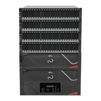
Overview This chapter provides an overview and describes the features of the ETERNUS DX. Product Lineup The ETERNUS DX600 S6 and ETERNUS DX900 S6 are midrange Hybrid Storage System models. Figure 1 Configuration Example for Each ETERNUS DX Midrange model: ETERNUS DX600 S6 2.5”... -
Page 19: Eternus Dx600 S6
1. Overview Product Lineup ETERNUS DX600 S6 This section provides the storage system specification of the ETERNUS DX600 S6. Table 1 Specifications (ETERNUS DX600 S6) Item ETERNUS DX600 S6 Physical capacity (max.) NVMe SSDs 2,949TB (*1) SAS SSDs 28,754TB SAS disks... -
Page 20: Eternus Dx900 S6
1. Overview Product Lineup *2: Extreme Cache Pools use the NVMe SSDs (3.2TB) that are installed in the controller enclosures or NVMe type drive enclosures as the cache. Up to four drives can be installed for the Extreme Cache Pools per controller and the maximum capacity of the Extreme Cache Pools in each controller is 12.8TB. - Page 21 1. Overview Product Lineup Item ETERNUS DX900 S6 Drive capacity 2.5" NVMe SSDs Non-self-encrypting 1.92TB, 3.2TB (*7), 3.84TB, 7.68TB, 15.36TB (rotational speed) Self-encrypting 1.92TB, 3.2TB (*7), 3.84TB, 7.68TB, 15.36TB 2.5" SAS SSDs Non-self-encrypting 1.92TB, 3.84TB, 7.68TB, 15.36TB, 30.72TB Self-encrypting 1.92TB, 3.84TB, 7.68TB 2.5"...
-
Page 22: Function Specification List
1. Overview Function Specification List Function Specification List The ETERNUS DX provides various functions to ensure data integrity, enhance security, reduce cost, and optimize the overall performance of the system. These functions enable users to respond to problems from various situations. For the ETERNUS DX, basic functions are used during normal operation and expansion functions are used in certain situations. -
Page 23: Table 4 Expansion Functions
1. Overview Function Specification List Overview Function High-speed backup "Backup" (page 99) • Continuous business • Data can be duplicated at any point without affecting other operations. Performance tuning "Assigned CMs" (page 120) Functions that can perform tuning in order to improve "Striping Size Expansion"... -
Page 24: Basic Functions
Basic Functions This chapter describes the functions that control the storage system. If Multitenancy is being used, the function that the tenant user can operate is restricted. For details, refer "Multitenancy" (page 132). RAID Functions This section explains the points to note before configuring a system using the ETERNUS DX. Supported RAID The ETERNUS DX supports the following RAID levels. -
Page 25: Table 5 Raid Level Comparison
2. Basic Functions RAID Functions • RAID5 (Striping with Distributed Parity) Data is divided into blocks and allocated across multiple drives together with parity information created from the data in order to ensure the redundancy of the data. • RAID5+0 (Double Striping with Distributed Parity) Multiple RAID5 volumes are RAID0 striped. -
Page 26: User Capacity (Logical Capacity)
2. Basic Functions RAID Functions User Capacity (Logical Capacity) User Capacity for Each RAID Level The user capacity depends on the capacity of drives that configure a RAID group and the RAID level. Table 6 shows the formula for calculating the user capacity for each RAID level. Table 6 Formula for Calculating User Capacity for Each RAID Level RAID level... -
Page 27: Raid Group
*2: This value is for a 30.72TB SAS SSD RAID1+0 (4D+4M) configuration. *3: This value is for a 30.72TB SAS SSD RAID1+0 (4D+4M) configuration in the ETERNUS DX600 S6. Up to two REC Disk Buffers can be installed for each ETERNUS DX. -
Page 28: Figure 2 Example Of A Raid Group
2. Basic Functions RAID Functions The same size drives (2.5" or 3.5"), the same kind of drives (NVMe SSDs, SAS SSDs, SAS disks, Nearline SAS disks, or SEDs), and the same capacity drives must be used to configure a RAID group. Figure 2 Example of a RAID Group NVMe... - Page 29 2. Basic Functions RAID Functions • Sequential access performance hardly varies with the number of drives for the RAID group. • Random access performance tends to be proportional to the number of drives for the RAID group. • Use of higher capacity drives will increase the time required for the drive rebuild process to complete.
-
Page 30: Volume
Number of Volumes That Can Be Created Maximum number of volumes (per RAID Maximum number of volumes (per Model group) storage system) ETERNUS DX600 S6 16,384 16,384 ETERNUS DX900 S6 65,535 65,535 A volume can be expanded or moved if required. Multiple volumes can be concatenated and treated as a single volume. - Page 31 2. Basic Functions RAID Functions Type Usage Maximum capacity Flexible Tier Volume (FTV) This volume is a target volume for layering. Data is 128TB automatically redistributed in small block units according to the access frequency. FTVs are used as the copy destination for SnapOPC+.
-
Page 32: Hot Spare
2. Basic Functions RAID Functions the ETERNUS DX decreases by the number of volumes for the VVOL management information that are created. Hot Spare Hot spares are used as spare drives for when drives in a RAID group fail, or when drives are in error status. -
Page 33: Table 12 Number Of Installable Hot Spares (1/3)
2. Basic Functions RAID Functions ■ Number of Installable Hot Spares The number of required hot spares is determined by the total number of drives. The following table shows the recommended number of hot spares for each drive type. Table 12 Number of Installable Hot Spares (1/3) Total number of drives Model... -
Page 34: Figure 5 Hot Spare Selection Criteria (For The Eternus Dx600 S6)
Hot spare selection criteria (search order for drive enclosures) Drive enclosures that meet the following criteria are searched. Table 15 Hot Spare Selection Criteria – Search Order for Drive Enclosures (ETERNUS DX600 S6) Priority order Selection criteria A drive enclosure that is located in the same path as the failed drive A drive enclosure that is not located in the same path as the failed drive (*1) •... -
Page 35: Table 17 Hot Spare Selection Criteria - Search Order For Drive Enclosures (Eternus Dx900 S6)
2. Basic Functions RAID Functions Priority order 1 Priority order 2 ● For the ETERNUS DX900 S6 • Hot spare selection criteria (search order for drive enclosures) Drive enclosures that meet the following criteria are searched. Table 17 Hot Spare Selection Criteria – Search Order for Drive Enclosures (ETERNUS DX900 S6) Priority order Selection criteria •... -
Page 36: Figure 6 Hot Spare Selection Criteria - Search Order For Drive Enclosures (Eternus Dx900 S6, Example 1)
2. Basic Functions RAID Functions Figure 6 Hot Spare Selection Criteria – Search Order for Drive Enclosures (ETERNUS DX900 S6, Example 1) RAID group CE#0 Priority order 3 DE#01 DE#02 DE#E3 DE#04 DE#05 DE#06 DE#E7 Priority order 1 Failure DE#08 DE#09 DE#0A DE#EB Priority order 3 DE#0C DE#0D DE#0E DE#EF... -
Page 37: Data Protection
2. Basic Functions Data Protection Data Protection Data Block Guard When a write request is issued by a server, the data block guard function adds check codes to all of the data that is to be stored. The data is verified at multiple checkpoints on the transmission paths to ensure data integrity. -
Page 38: Disk Drive Patrol
2. Basic Functions Data Protection The T10-DIF function can be enabled or disabled for each volume when the volumes are created. This function cannot be enabled or disabled after a volume has been created. • The T10-DIF function can be enabled only in the Standard volume. •... -
Page 39: Redundant Copy
2. Basic Functions Data Protection The Maintenance Operation privilege is required to set detailed parameters. Redundant Copy Redundant Copy is a function that copies the data of a drive that shows a possible sign of failure to a hot spare. When the Disk Patrol function determines that a drive requires preventative maintenance, the data of the maintenance target drive is recreated by the remaining drives and written to the hot spare. -
Page 40: Rebuild
2. Basic Functions Data Protection Rebuild Rebuild processes recover data in failed drives by using other drives. If a free hot spare is available when one of the RAID group drives has a problem, data of this drive is automatically replicated in the hot spare. -
Page 41: Fast Recovery
2. Basic Functions Data Protection Fast Recovery This function recovers data quickly by relocating data in the failed drive to the other remaining drives when a drive error is detected. For a RAID group that is configured with RAID6-FR, Fast Recovery is performed for the reserved area that is equivalent to hot spares in the RAID group when a drive error occurs. -
Page 42: Copyback/Copybackless
2. Basic Functions Data Protection Copyback/Copybackless A Copyback process copies data in a hot spare to the new drive that is used to replace the failed drive. Figure 13 Copyback drive Replace After rebuilding has been completed, replaces the failed drive with the new drive. Failed drive RAID5 (Redundant) Copyback... -
Page 43: Figure 14 Copybackless
2. Basic Functions Data Protection • Capacity • Rotational speed (10,000rpm and 7,200rpm) (*1) *1: For SAS disks or Nearline SAS disks (including SEDs) only. If different types of drives have been selected as the hot spare, copyback is performed after replacing the drives even when the Copybackless function is enabled. -
Page 44: Protection (Shield)
2. Basic Functions Data Protection Protection (Shield) The Protection (Shield) function diagnoses temporary drive errors. A drive can continue to be used if it is determined to be normal. The target drive temporarily changes to diagnosis status when drive errors are detected by the Disk Drive Patrol function or error notifications. - Page 45 2. Basic Functions Data Protection • The target drives are disconnected and then reconnected during temporary drive protection. Even though a system status error may be displayed during this period, this phenomenon is only temporary. The status returns to normal after the diagnosis is complete. The following phenomenon may occur during temporary drive protection.
-
Page 46: Reverse Cabling
If a drive enclosure fails for any reason, access to drives installed in the drive enclosures subsequent to the failed drive enclosure is maintained because normal access paths are secured by using reverse cabling. Figure 16 Reverse Cabling (for ETERNUS DX600 S6) DE#06 DE#06 IOM#0... -
Page 47: Operations Optimization (Virtualization/Automated Storage Tiering Control)
2. Basic Functions Operations Optimization (Virtualization/Automated Storage Tiering Control) Operations Optimization (Virtualization/Automated Storage Tiering Control) Thin Provisioning Thin Provisioning has the following features: Storage Capacity Virtualization • The physical storage capacity can be reduced by allocating the virtual drives to a server, which allows efficient use of the storage capacity. -
Page 48: Table 19 Maximum Pool Capacity And Required Number Of Drives
2. Basic Functions Operations Optimization (Virtualization/Automated Storage Tiering Control) If the Thin Provisioning function is used, the drives must be installed as follows for the maximum pool capacity. The drive type and capacity are not restricted. Table 19 Maximum Pool Capacity and Required Number of Drives Are the Required Required drive installation slot... -
Page 49: Figure 17 Storage Capacity Virtualization
The following table shows the maximum number and the maximum capacity of TPPs that can be registered in the ETERNUS DX. Table 20 TPP Maximum Number and Capacity Item ETERNUS DX600 S6 ETERNUS DX900 S6 Maximum number of pools (*1) Maximum pool capacity (*2) 98,304TB... -
Page 50: Table 21 Chunk Size According To The Configured Tpp Capacity
*1 : Chunk size is for delimiting data. The chunk size is automatically set according to the maximum pool capacity. *2: If the maximum pool capacity is set to 512PB (or 96PB for the ETERNUS DX600 S6), the chunk size can be manually set when pools are created. -
Page 51: Table 23 Tpp Thresholds
2. Basic Functions Operations Optimization (Virtualization/Automated Storage Tiering Control) Thick When creating a volume, the physical area is allocated to the entire volume area. This can be used for volumes in the system area to prevent a system stoppage due to a pool capacity shortage during operations. - Page 52 2. Basic Functions Operations Optimization (Virtualization/Automated Storage Tiering Control) • Use of Thin Provisioning is also not recommended when the OS writes meta information to the whole LUN during file system creation. • TPVs should be backed up by file. While backing up a whole TPV is not difficult, unallocated areas will also be backed up as dummy data.
-
Page 53: Figure 18 Tpv Balancing (When Allocating Disproportionate Tpv Physical Capacity Evenly)
2. Basic Functions Operations Optimization (Virtualization/Automated Storage Tiering Control) TPV Balancing A drive is allocated when a write is issued to a virtual volume (TPV). Depending on the order and the frequency of writes, more drives in a specific RAID group may be allocated disproportionately. Also, the physical capacity is unevenly allocated among the newly added RAID group and the existing RAID groups when physical drives are added to expand the capacity. - Page 54 2. Basic Functions Operations Optimization (Virtualization/Automated Storage Tiering Control) ■ Balancing Level The TPV balance status is displayed by three levels; "High", "Middle", and "Low". "High" indicates that the physical capacity of TPV is allocated evenly in the RAID groups registered in the TPP. "Low" indicates that the physical capacity is allocated unequally to a specific RAID group in the TPP.
-
Page 55: Figure 20 Tpv/Ftv Capacity Optimization
2. Basic Functions Operations Optimization (Virtualization/Automated Storage Tiering Control) TPV/FTV Capacity Optimization TPV/FTV capacity optimization can increase the unallocated areas in a pool (TPP/FTRP) by changing the physical areas where 0 is allocated for all of the data to unallocated areas. This improves functional efficiency. -
Page 56: Flexible Tier
2. Basic Functions Operations Optimization (Virtualization/Automated Storage Tiering Control) Flexible Tier Flexible Tier provides the following functions: • Automated Storage Tiering This function automatically reallocates data according to the data access frequency and optimizes performance and cost. • FTRP Balancing I/O access to a virtual volume can be distributed among the RAID groups in a pool by relocating and balancing the physical areas allocated to the virtual volume. -
Page 57: Figure 21 Flexible Tier
2. Basic Functions Operations Optimization (Virtualization/Automated Storage Tiering Control) Figure 21 Flexible Tier Management server ETERNUS DX Monitors the data access frequency ETERNUS SF and optimizes performance Storage Cruiser Work volume High (High speed) SAS disks (High speed) Nearline SAS disks Access (Large capacity, low-cost) frequency... -
Page 58: Table 26 The Maximum Number And The Maximum Capacity Of Ftsps
ETERNUS DX. Table 26 The Maximum Number and the Maximum Capacity of FTSPs Item ETERNUS DX600 S6 ETERNUS DX900 S6 Maximum number of Flexible Tier Pools Maximum number of Flexible Tier Sub Pools (*1) Maximum capacity of the Flexible Tier Sub Pools... -
Page 59: Table 28 Ftrp Thresholds
2. Basic Functions Operations Optimization (Virtualization/Automated Storage Tiering Control) Thick When creating a volume, the physical area is allocated to the entire volume area. This can be used for volumes in the system area to prevent a system stoppage due to a pool capacity shortage during operations. -
Page 60: Figure 23 Ftrp Balancing
2. Basic Functions Operations Optimization (Virtualization/Automated Storage Tiering Control) FTRP Balancing When drives are added to a pool, the physical capacity may be allocated unevenly among the RAID groups in the pool. By using the Flexible Tier Pool balancing function, the allocated physical capacity as well as the usage rate of the physical disks in the pool can be balanced. -
Page 61: Extreme Cache Pool
2. Basic Functions Operations Optimization (Virtualization/Automated Storage Tiering Control) • If the free capacity in the FTSP becomes insufficient while FTRP balancing is being performed, an error occurs and the balancing session ends abnormally. Note that insufficient physical capacity cannot be replaced by other FTSPs. •... -
Page 62: Optimization Of Volume Configurations
For details on the installation conditions of Extreme Cache Pool, refer to "Drive" (page 208). Table 30 Maximum Installed Number of Extreme Cache Pools and Their Maximum Capacity Item ETERNUS DX600 S6 ETERNUS DX900 S6 Maximum installed number of Extreme Cache Pools (per storage system) Maximum Extreme Cache Pool capacity 25.6TB 51.2TB... - Page 63 2. Basic Functions Optimization of Volume Configurations ■ Expansion of RAID Group Capacity • Logical Device Expansion Adds new drives to an existing RAID group to expand the RAID group capacity. This is used to expand the existing RAID group capacity instead of adding a new RAID group to add the volumes. ■...
-
Page 64: Raid Migration
2. Basic Functions Optimization of Volume Configurations RAID Migration RAID Migration is a function that moves a volume to a different RAID group with the data integrity being guaranteed. This allows easy redistribution of volumes among RAID groups in response to customer needs. -
Page 65: Figure 27 Raid Migration
2. Basic Functions Optimization of Volume Configurations • Changing the number of concatenations and the Wide Stripe Size (for WSV) • Enabling the Deduplication/Compression function for existing volumes The following processes can also be specified. • Capacity expansion When migration between RAID groups is performed, capacity expansion can also be performed at the same time. -
Page 66: Logical Device Expansion
2. Basic Functions Optimization of Volume Configurations Logical Device Expansion Logical Device Expansion (LDE) allows the capacity of an existing RAID group to be dynamically expanded by changing of the RAID level or the drive configuration of the RAID group. When this function is performed, drives can be also added at the same time. - Page 67 2. Basic Functions Optimization of Volume Configurations For details on the functions that can be executed simultaneously and the number of simultaneous executions, refer to "Combinations of Functions That Are Available for Simultaneous Executions" (page 240). Since the data cannot be recovered after the failure of LDE, back up all the data of the volumes in •...
-
Page 68: Lun Concatenation
2. Basic Functions Optimization of Volume Configurations LUN Concatenation LUN Concatenation is a function that is used to add new area to a volume and so expand the volume capacity available to the server. This function enables the reuse of leftover free area in a RAID group and can be used to solve capacity shortages. -
Page 69: Figure 31 Lun Concatenation (Volume Concatenation)
2. Basic Functions Optimization of Volume Configurations Figure 31 LUN Concatenation (Volume Concatenation) 10GB Concatenation Unused area 20GB 30GB 60GB Only Standard type volumes can be used for LUN Concatenation. The encryption status of a concatenated volume is the same status as a volume that is to be concatenated. LUN Concatenation may not be available when other functions are being used in the ETERNUS DX or the target volume. -
Page 70: Wide Striping
2. Basic Functions Optimization of Volume Configurations Wide Striping Wide Striping is a function that concatenates multiple RAID groups by striping and uses many drives simultaneously to improve performance. This function is effective when high random write performance is required. I/O accesses from the server are distributed to multiple drives by increasing the number of drives that configure a LUN, which improves the processing performance. -
Page 71: Data Encryption
AES (*1) or Fujitsu Original Encryption can be selected as the encryption method. The Fujitsu Original Encryption method uses a Fujitsu original algorithm that has been specifically created for ETERNUS DX storage systems. -
Page 72: Encryption With Self Encrypting Drive (Sed)
2. Basic Functions Data Encryption Encryption with Self Encrypting Drive (SED) An SED has a built-in encryption function and data can be encrypted by controlling the encryption function of an SED from the controller. An SED uses encryption keys when encrypting and storing data. Encryption keys cannot be taken out of the drive. -
Page 73: Firmware Data Encryption
The encryption method can be selected from the world standard AES-128, the world standard AES-256, and the Fujitsu Original Encryption method. The Fujitsu Original Encryption method that is based on AES technology uses a Fujitsu original algorithm that has been specifically created for ETERNUS DX storage systems. - Page 74 2. Basic Functions Data Encryption • It is recommended that the copy source volume and the copy destination volume use the same encryption method for Remote Advanced Copy between encrypted volumes. • When copying encrypted volumes (using Advanced Copy or copy operations via server OS), transfer performance may not be as good as when copying unencrypted volumes.
-
Page 75: User Access Management
2. Basic Functions User Access Management User Access Management Account Management The ETERNUS DX uses roles to allocate access authority when a user account is created, and sets which functions can be used depending on the user privileges. Since the authorized functions of the storage administrator are classified according to the usage and only minimum privileges are given to the administrator, security is improved and operational mistakes and management hours can be reduced. -
Page 76: Table 33 Available Functions For Default Roles
2. Basic Functions User Access Management • Roles and available functions Seven default roles are provided in the ETERNUS DX. The following table shows the roles and the available functions (privileges). Table 33 Available Functions for Default Roles Roles Privilege Software Storage Account... -
Page 77: User Authentication
2. Basic Functions User Access Management User Authentication Internal Authentication and External Authentication are available as login authentication methods. RADIUS authentication can be used for External Authentication. ■ Internal Authentication Internal Authentication is performed using the authentication function of the ETERNUS DX. The following authentication functions are available when the ETERNUS DX is connected via a LAN using operation management software. - Page 78 Item Value Description (octets) Length 7 or more Attribute size (calculated by server) Vendor-Id Fujitsu Limited (SMI Private Enterprise Code) Vendor type Eternus-Auth-Role Vendor length 2 or more Attribute size described after the "Vendor type" item (calculated by server) Attribute-Specific...
-
Page 79: Audit Log
2. Basic Functions User Access Management Audit Log The ETERNUS DX can send information such as access records by the administrator and setting changes as audit logs to the Syslog servers. Audit logs are audit trail information that record operations that are executed for the ETERNUS DX and the response from the system. -
Page 80: Improving Host Connectivity
2. Basic Functions Improving Host Connectivity Improving Host Connectivity Host Affinity The host affinity function prevents data from being damaged due to inadvertent storage access. By defining a server that can access the volume, security can be ensured when multiple servers are connected. -
Page 81: Figure 38 Associating Host Groups, Ca Port Groups, And Lun Groups
2. Basic Functions Improving Host Connectivity Figure 38 Associating Host Groups, CA Port Groups, and LUN Groups Host group 1 ETERNUS DX Server A LUN group 1 CE#1 Switch Port Vol#0 Vol#1 Vol#2 Server B Port Switch CA port group 1 CA port group 2 Server C CE#0... -
Page 82: Iscsi Security
2. Basic Functions Improving Host Connectivity iSCSI Security For an iSCSI interface, the iSCSI authentication function can be used when the initiator accesses the target. The iSCSI authentication function is available for host connections and remote copying. The Challenge Handshake Authentication Protocol (CHAP) is supported for iSCSI authentication. For CHAP Authentication, unidirectional CHAP or bidirectional CHAP can be selected. -
Page 83: Environmental Burden Reduction
2. Basic Functions Environmental Burden Reduction Environmental Burden Reduction Eco-mode Eco-mode is a function that reduces power consumption for limited access disks by stopping the disks rotation during specified periods or by powering off the disks. Disk spin-up and spin-down schedules can be set for each RAID group or TPP. These schedules can also be set to allow backup operations. -
Page 84: Table 35 Eco-Mode Specifications
2. Basic Functions Environmental Burden Reduction • FTSP For RAID groups with the following conditions, the Eco-mode schedule can be set but the disks motor cannot be stopped or the power supply cannot be turned off: SDPVs are registered • ODX Buffer volumes are registered •... - Page 85 2. Basic Functions Environmental Burden Reduction • To set Eco-mode schedules, use ETERNUS Web GUI, ETERNUS CLI, ETERNUS SF Storage Cruiser, or ETERNUS SF AdvancedCopy Manager. Note that schedules that are created by ETERNUS Web GUI or ETERNUS CLI and schedules that are created by ETERNUS SF Storage Cruiser or ETERNUS SF AdvancedCopy Manager cannot be shared.
- Page 86 2. Basic Functions Environmental Burden Reduction The operation time of disks varies depending on the Eco-mode schedule and the disk access. • Access to a stopped disk outside of the scheduled operation time period causes the motor of the stopped disk to be spun up, allowing normal access in about one to five minutes. When a set time elapses since the last access to a disk, the motor of the disk is stopped.
-
Page 87: Power Consumption Visualization
2. Basic Functions Environmental Burden Reduction Power Consumption Visualization The power consumption and the temperature can be visualized with a graph by using the ETERNUS SF Storage Cruiser integrated management software in a storage system environment. The ETERNUS DX collects information on power consumption and the ambient temperature. Collected information is notified using SNMP and graphically displayed on the screens by ETERNUS SF Storage Cruiser. -
Page 88: Operation Management/Device Monitoring
■ ETERNUS SF ETERNUS SF can manage storage environments that center on Fujitsu storage products. An easy-to-use interface enables complicated storage environment design and setting operations, which allows easy installation of a storage system without needing to have high level skills. -
Page 89: Table 36 Features Of The Operation Management Interfaces
Host settings • • User benefits A FUJITSU GUI Next Plus compliant design makes it easy to focus on content Simple, intuitive operation A screen and function design that can be used without knowledge of the ETERNUS series Design Guide... -
Page 90: Table 37 Comparison Of Operation Management Interfaces (1/2)
2. Basic Functions Operation Management/Device Monitoring Operation Management Features Interface ETERNUS CLI • Supported functions All functions for device operation and management, and some maintenance functions Status display and monitoring Configuration settings and tuning • RAID group and TPP settings •... -
Page 91: Performance Information Management
2. Basic Functions Operation Management/Device Monitoring Feature Operation management interface Easy to see information Operability Script operation Light processing ◎ ◎ ETERNUS Web GUI ´ ¡ (Easy Administration View) △ △ ◎ ETERNUS CLI ¡ ◎ ◎ RESTful API — —... - Page 92 2. Basic Functions Operation Management/Device Monitoring • Prefetch Cache Hit Rate (cache hit rate for prefetch) • Extreme Cache Hit Rate ■ Controller Performance Information Busy Ratio (CPU usage) • CPU Core Usage • ■ CA Port Performance Information • Read IOPS (the read count per second) Write IOPS (the write count per second) •...
-
Page 93: Event Notification
2. Basic Functions Operation Management/Device Monitoring Event Notification When an error occurs in the ETERNUS DX, the event notification function notifies the event information to the administrator. The administrator can be informed that an error occurred without monitoring the screen all the time. The methods to notify an event are e-mail, SNMP Trap, syslog, remote support, and host sense. -
Page 94: Simple Network Management Protocol (Snmp)
2. Basic Functions Operation Management/Device Monitoring ■ Simple Network Management Protocol (SNMP) Using the SNMP agent function, management information is sent to the SNMP manager (network management/monitoring server). The ETERNUS DX supports the following SNMP specifications. Table 40 SNMP Specifications Item Specification Remarks... -
Page 95: Device Time Synchronization
2. Basic Functions Operation Management/Device Monitoring Device Time Synchronization The ETERNUS DX treats the time that is specified in the Main CM as the system standard time and distributes that time to other modules to synchronize the storage time. The ETERNUS DX also supports the time correction function by using the Network Time Protocol (NTP). -
Page 96: Remote Support
2. Basic Functions Power Control Remote Support This function sends e-mails to the remote support center to report various failures that occur in the ETERNUS DX. ■ REMCS Remote support has the following maintenance functions. • Failure notice This function reports various failures, that occur in the ETERNUS DX, to the remote support center. The maintenance engineer is notified of a failure immediately. -
Page 97: Backup (Advanced Copy)
2. Basic Functions Backup (Advanced Copy) Backup (Advanced Copy) The Advanced Copy function (high-speed copying function) enables data backup (data replication) at any point without stopping business operations. For an ETERNUS DX backup operation, data can be replicated without placing a load on the business server. -
Page 98: Table 42 List Of Advanced Copy Specifications
"Combinations of Functions That Are Available for Simultaneous Executions" (page 240). Table 42 List of Advanced Copy Specifications Specification ETERNUS DX600 S6 ETERNUS DX900 S6 Maximum number of sessions (*1) 8,192 32,768 Maximum number of copy source and copy destination areas... -
Page 99: Backup
2. Basic Functions Backup (Advanced Copy) Backup Local Copy The Advanced Copy functions offer the following copy methods: "Mirror Suspend", "Background Copy", and "Copy-on-Write". The function names that are given to each method are as follows: "EC" for the "Mirror Suspend" method, "OPC" for the "Background Copy" method, and "SnapOPC" for the "Copy-on- Write"... -
Page 100: Table 43 Characteristics Of Snapopc/Snapopc+ Operations With Each Type Of Copy Destination Logical Volume
2. Basic Functions Backup (Advanced Copy) • SnapOPC/SnapOPC+ operations that use an SDV/TPV/FTV as the copy destination logical volume have the following characteristics. Check the characteristics of each volume type before selecting the volume type. Table 43 Characteristics of SnapOPC/SnapOPC+ Operations with Each Type of Copy Destination Logical Volume Item to compare TPV/FTV... - Page 101 2. Basic Functions Backup (Advanced Copy) • Volume type of the copy destination To perform a generation backup with SnapOPC+, the volumes within one backup group have the following restrictions. • SDV and TPV cannot be mixed in the copy destination of each generation. •...
-
Page 102: Remote Copy
2. Basic Functions Backup (Advanced Copy) • Reusing copy destination volumes Copy destination TPVs/FTVs of SnapOPC+ can be reused as work volumes. After canceling a copy session, use the TPVs/FTVs once they are formatted. For details, refer to "Format Volume" of ETERNUS Web GUI. -
Page 103: Table 44 Rec Data Transfer Mode
2. Basic Functions Backup (Advanced Copy) Figure 45 Main site Backup site Management server Management server ETERNUS AF/DX Remote copy ETERNUS AF/DX (REC) Operating Backup volume volume The REC data transfer mode has two modes: the synchronous transfer mode and the asynchronous transfer mode. These modes can be selected according to whether importance is placed upon I/O response time or complete backup of the data is performed until the point when a disaster occurs. - Page 104 When a capacity shortage for the REC Buffer occurs, the REC Disk Buffer can also be used. A REC Disk Buffer is used as a temporary destination to save copy data. ETERNUS DX900 S6 Specification ETERNUS DX600 S6 Number of REC disk buffers allocated (per REC 1 or 2 1 or 2...
- Page 105 2. Basic Functions Backup (Advanced Copy) REC Disk Buffers can only be used if the ETERNUS DX set as the REC Buffer (for transmission) and the ETERNUS DX set for the REC Buffer (for reception) both support REC Disk Buffers. The following models, which can execute remote copies with the ETERNUS DX S6 series, support REC Disk Buffers.
-
Page 106: Figure 46 Restore Opc
2. Basic Functions Backup (Advanced Copy) Available Advanced Copy Combinations Different Advanced Copy types can be combined and used together. ■ Restore OPC After sending instructions to implement OPC, QuickOPC, SnapOPC, and/or SnapOPC+, data can be restored by implementing OPC from the copy destination to the copy source. Because it is OPC, logical copies are completed instantly. -
Page 107: Figure 48 Targets For The Multi-Copy Function
2. Basic Functions Backup (Advanced Copy) Figure 48 Targets for the Multi-Copy Function Copy Copy Copy source destination 1 destination 2 Copy session 1 Update 1 Area A Update 2 Copy session 2 Up to eight OPC, QuickOPC, SnapOPC, EC, or REC sessions can be set for a multi-copy. Figure 49 Multi-Copy ETERNUS AF/DX... -
Page 108: Figure 51 Multi-Copy (Using The Consistency Mode)
2. Basic Functions Backup (Advanced Copy) Note that when the Consistency mode is used, a multi-copy from a single copy source area to two or more copy destination areas in a single copy destination storage system cannot be specified. A multi- copy from the same copy source area to different copy destination storage systems can be specified. -
Page 109: Figure 52 Multi-Copy
2. Basic Functions Backup (Advanced Copy) Figure 53 Multi-Copy (Case 2: When Performing a Cascade Copy for an REC Session in Consistency Mode) ETERNUS AF/DX ETERNUS AF/DX OPC / QuickOPC / REC (Consistency) Copy Copy destination 1 source REC (Consistency) OPC / Copy QuickOPC / destination 2 ETERNUS AF/DX Copy REC (Consistency) destination 3 ■... -
Page 110: Table 45 Available Cascade Copy Combinations (When A Cascade Copy Performs Session 1 Followed By Session 2)
2. Basic Functions Backup (Advanced Copy) Table 45 Available Cascade Copy Combinations (When a Cascade Copy Performs Session 1 Followed by Session 2) Copy session 1 Copy session 2 REC Stack REC Consistency QuickOPC SnapOPC SnapOPC+ synchronous mode mode transmission ¡... -
Page 111: Table 47 Available Cascade Copy Combinations (When A Cascade Copy Performs Session 2 Followed By Session 1)
2. Basic Functions Backup (Advanced Copy) Table 47 shows the supported combinations when adding a copy session to a copy source volume where a copy session has already been configured. Table 47 Available Cascade Copy Combinations (When a Cascade Copy Performs Session 2 Followed by Session 1) Copy session 2 Copy session 1... - Page 112 2. Basic Functions Backup (Advanced Copy) • If copy session 2 is an EC or REC session, copy session 2 does not transition to an equivalent state until the physical copy for copy session 1 is complete. For an EC session, a copy session cannot be suspended until the session transitions to an equivalent state.
-
Page 113: Figure 55 Cascade Copy (Using Three Copy Sessions)
2. Basic Functions Backup (Advanced Copy) A Cascade Copy that uses the three copy sessions can be performed with the following configuration. Figure 55 Cascade Copy (Using Three Copy Sessions) OPC / QuickOPC / SnapOPC / SnapOPC+ / OPC / QuickOPC / REC (Stack mode) Copy source Copy destination... -
Page 114: Figure 45 Rec
2. Basic Functions Backup (Advanced Copy) When two sets of copy sessions are already set, the destination volume of the first copy session can be set as the copy source of the second copy session. Figure 58 Cascade Copy (Adding a Different Copy Session between Two Sets of Copy Sessions) ETERNUS AF/DX QOPC Copy source... -
Page 115: Figure 60 Opc Restoration From The Cascade State
2. Basic Functions Backup (Advanced Copy) ■ OPC Restoration or EC/REC Reverse from the Cascade Copy State There are restrictions for the available Cascade Copy combinations when copy session 2 (OPC Restoration or EC/REC Reverse) is restored from the cascade copy state. For details, refer to Table 48 Table Figure 60... -
Page 116: Figure 62 Ec/Rec Reverse From The Cascade State (2)
2. Basic Functions Backup (Advanced Copy) • Reverse of copy session 2 is allowed after copy session 1 is reversed. Figure 62 EC/REC Reverse from the Cascade State (2) EC / REC EC / REC Copy source Copy destination Copy destination + copy source Reverse EC / REC... -
Page 117: Figure 63 Cascade Copy (Inversion Of Cascade Copy 1)
2. Basic Functions Backup (Advanced Copy) Table 49 Restrictions on the Availability of OPC Restoration or EC/REC Reverse during Cascade Copy (2/2) Copy session 1 Synchrono REC Stack REC Consistency Copy session 2 for OPC Restoration ¡ (*2) ¡ (*2) ¡... -
Page 118: Figure 64 Cascade Copy (Inversion Of Cascade Copy 2)
2. Basic Functions Backup (Advanced Copy) To perform a restore with the following copy session combinations, reverse the order of the copy source and copy destination from the copy session of the cascade source after deleting the copy session of QuickOPC. -
Page 119: Figure 65 Mixture Of Cascade Copy And Multi-Copy
2. Basic Functions Backup (Advanced Copy) ■ Mixture of Cascade Copy and Multi-Copy Cascade Copy and multi-copy can be performed at the same time. Figure 65, "Copy session 1" refers to a copy session in which the copy destination area is also used as the copy source area of another copy session. -
Page 120: Performance Tuning
2. Basic Functions Performance Tuning Performance Tuning Assigned CMs A controller that controls access is assigned to each RAID group and manages the load balance in the ETERNUS DX. The controller that controls a RAID group is called an assigned CM. Figure 66 Assigned CMs Switch... -
Page 121: Striping Size Expansion
2. Basic Functions Performance Tuning Table 51 Auto Assignment of Assigned CMs (for 4 CMs) Number of CMs (number of CEs) The remainder when the RAID group number is divided by the number of controllers 2 (1CE) 4 (2CE) CE#0 CM#0 CE#0 CM#0 CE#0 CM#1 CE#1 CM#1... -
Page 122: Expansion Functions
Expansion Functions This chapter describes the functions that are available when a SAN connection is used. If Multitenancy is being used, the function that the tenant user can operate is restricted. For details, refer "Multitenancy" (page 132). Operations Optimization (Deduplication/Compression) The Deduplication function cannot be used in the ETERNUS DX900 S6. -
Page 123: Figure 67 Deduplication/Compression Overview
3. Expansion Functions Operations Optimization (Deduplication/Compression) ■ Deduplication/Compression Function This function removes duplicate data blocks, compresses the remaining data blocks, and then stores the data. Figure 67 Deduplication/Compression Overview Business server 1 Business server 2 Data 1 A B C D A B E Data 2 Data 1 is written... -
Page 124: Figure 68 Deduplication Overview
3. Expansion Functions Operations Optimization (Deduplication/Compression) ■ Deduplication Function This function removes duplicate data blocks and stores the data. Figure 68 Deduplication Overview Business server 1 Business server 2 Data 1 Data 2 A B C D A B E Data 1 is written Data 2 is written A B C D... -
Page 125: Table 52 Deduplication/Compression Function Specifications (Eternus Dx600 S6)
3. Expansion Functions Operations Optimization (Deduplication/Compression) The following table provides the function specifications for the Deduplication/Compression. Table 52 Deduplication/Compression Function Specifications (ETERNUS DX600 S6) Model ETERNUS DX600 S6 Number of TPPs available for Deduplication/Compression settings Maximum logical capacity that can be a deduplication/compression target... -
Page 126: Configuration Method
3. Expansion Functions Operations Optimization (Deduplication/Compression) ■ Performance When Using the Deduplication/Compression Function The ETERNUS DX performs data deduplication/compression in synchronization with the I/O from the server. • Using this function in environments where random access occurs is recommended. Data is intermittently stored in Deduplication/Compression Volumes because data is appended. -
Page 127: Table 55 Volumes That Are To Be Created Depending On The Selection Of "Deduplication" And "Compression
3. Expansion Functions Operations Optimization (Deduplication/Compression) Condition of the TPP Chunk size (*1) Creation method Existing TPP 21MB – 1,344MB (*3) Select a target TPP to enable the Deduplication/Compression function (*4) *1 : The chunk size can be checked in the list display of the TPP. *2: The chunk size can be changed only if the maximum pool capacity is selected. -
Page 128: Table 56 Deduplication/Compression Setting For Tpps Where The Target Volumes Can Be Created
3. Expansion Functions Operations Optimization (Deduplication/Compression) • Deduplication/Compression setting for TPPs where the volumes can be created Table 56 Deduplication/Compression Setting for TPPs Where the Target Volumes Can Be Created Condition Deduplication/Compression setting for the destination TPP Both Deduplication Both Deduplication Only Deduplication Only Compression Deduplication... - Page 129 3. Expansion Functions Operations Optimization (Deduplication/Compression) ■ Deduplication/Compression Volumes The physical capacity may temporarily be larger than the logical capacity that is written because data is appended in Deduplication/Compression Volumes. If the I/O load is high, the physical capacity may run out.
-
Page 130: Figure 70 Details Of The Deduplication/Compression Function
3. Expansion Functions Operations Optimization (Deduplication/Compression) ■ Functional Details Figure 70 Details of the Deduplication/Compression Function Server ETERNUS DX I/O request Thin Provisioning Pool (TPP) Maps the Deduplication/Compression Volume (or the virtual volume) and the actual written data Deduplication/ DATA_CNTNR Compression (TPV) Volume... -
Page 131: Table 57 Management Functions For Deduplication/Compression Volumes
3. Expansion Functions Operations Optimization (Deduplication/Compression) ■ Operation of the Deduplication/Compression Volumes The following table provides management functions for volumes related to Deduplication/Compression. Table 57 Management Functions for Deduplication/Compression Volumes Function Deduplication/Compression Volume DATA_CNTNR Volume Creation ´ (*1) ¡ Deletion ´... -
Page 132: User Access Management
3. Expansion Functions User Access Management User Access Management Multitenancy Multitenancy is a function that divides the management of resources on a per tenant basis so that one storage system can be shared by multiple organizations. Costs can be reduced compared to a single tenant with a dedicated storage, and the maintenance load can be reduced by consolidating the storage. -
Page 133: Stable Operation
3. Expansion Functions Stable Operation • There is no limit for each tenant for resources that are assigned to tenants. A resource can be assigned to a tenant if the total number of resources in all the tenants and common resources is within the maximum value of the storage system. -
Page 134: Figure 73 Copy Path Bandwidth Limit
3. Expansion Functions Stable Operation ■ REC Bandwidth Limit (Remote Copy QoS) A bandwidth upper limit can be set for each copy path in the remote copy session. Even if a specific path fails, the line bandwidth can be maintained without centralizing the load to other paths. -
Page 135: Host Response
3. Expansion Functions Stable Operation Host Response The response from the ETERNUS DX can be optimized by switching the setup information of the host response for each connected server. The server requirements of the supported functions, LUN addressing, and the method for command responses vary depending on the connection environments such as the server OS and the driver that will be used. -
Page 136: Storage Cluster
3. Expansion Functions Stable Operation Storage Cluster Storage Cluster is a function that allows continuous operations by using redundant connections to two ETERNUS DX storage systems so that even if the Primary storage fails, operations are switched to the Secondary storage. Operations can continue without stopping access from the server if there are unexpected problems or if the ETERNUS DX is in an error state due to severe failures. -
Page 137: Figure 76 Storage Cluster (A/A Mode)
3. Expansion Functions Stable Operation Figure 76 Storage Cluster (A/A Mode) Storage Cluster Business server controller Failover ETERNUS DX ETERNUS DX Device failure Primary storage Secondary storage For Storage Cluster settings, create TFO groups and specify the connection configuration and the policy for each group. - Page 138 3. Expansion Functions Stable Operation • TFO group A Transparent Failover (TFO) group is the operations unit for a failover in a single ETERNUS AF/DX, and a Storage Cluster failover is performed for each group. A TFO group has two states. "Active" indicates that access from a business server is enabled and "Standby"...
-
Page 139: Table 58 Storage Cluster Function Specifications
´ ¡ Copy path (connection between storage systems) Direct connection and remote connection Maximum configurable capacity (per storage system) 8,192TB (ETERNUS DX600 S6) 16,384TB (ETERNUS DX900 S6) Maximum number of TFO groups (per storage system) Failover Automatic ¡ Manual ¡... - Page 140 In addition, the switch connection topology is supported. • Deduplication/Compression volumes (for the ETERNUS DX900 S6, Compression volumes) cannot be used with Storage Cluster. *1: The ETERNUS DX S6 series refers to the ETERNUS DX600 S6/DX900 S6 or the ETERNUS DX8900 S6. Design Guide...
-
Page 141: Data Migration
3. Expansion Functions Data Migration Data Migration For the migration destination ETERNUS DX, select the same type and speed for the host interface as the migration source storage system. To change the host interface, it is recommended that a validation is performed in advance to avoid operational impact after the migration. - Page 142 3. Expansion Functions Data Migration Up to 16 migration source storage systems can be specified and up to eight migration paths can be created for each migration source storage system. The capacity of a volume that is to be specified as the migration destination area must be larger than the migration source volume capacity.
-
Page 143: Non-Disruptive Storage Migration
32 ports connected from the local storage system (per FC-Initiator port) Maximum number of migration target volumes that can be imported 8,192 (ETERNUS DX600 S6) to the local storage system (*1) 16,384 (ETERNUS DX900 S6) Maximum number of migration target volumes in the external storage... - Page 144 3. Expansion Functions Non-disruptive Storage Migration Add multipath connections between the local storage system and the business server. After disconnecting the multipath connection between the external storage system and the business server, use RAID Migration to read data from the migration target volume in the external storage system and write data to the migration destination volume in the local storage system.
-
Page 145: Server Linkage Functions
3. Expansion Functions Server Linkage Functions Server Linkage Functions VMware Linkage By linking with "VMware vSphere" (which virtualizes platforms) and "VMware vCenter Server" (which supports integrated management of VMware vSphere), the resources of the ETERNUS DX can be effectively used and system performance can be improved. In addition, by supporting Virtual Volumes that are supported by VMware vSphere 6, the system can be efficiently operated. - Page 146 3. Expansion Functions Server Linkage Functions VMware VASA vStorage API for Storage Awareness (VASA) is an API that enables vCenter Server to link with the storage system and obtain storage system information. VASA can be used to integrate the virtual infrastructure of the storage with VMware and to enhance the Distributed Resource Scheduling (DRS) function and the troubleshooting efficiency.
-
Page 147: Figure 81 Vvol (Operational Configuration)
3. Expansion Functions Server Linkage Functions VMware VVOL The ETERNUS DX supports Virtual Volumes (VVOLs) that are VMware vSphere dedicated logical volumes. When using VVOLs, they are automatically created and copied in the ETERNUS DX while VMs are operated from vSphere Client. As a result, operations can be simplified by eliminating the need to configure logical volumes and backups in the ETERNUS DX. -
Page 148: Figure 82 Vvol (System Configuration)
3. Expansion Functions Server Linkage Functions Figure 82 VVOL (System Configuration) vSphere vSphere VVOL VVOL VVOL VVOL VVOL management information Storage container Storage container ETERNUS DX ● PEs are control volumes to integrally manage multiple VVOLs. ● Storage Container (VVOL Datastore) Storage containers are pools for creating VVOLs. -
Page 149: Table 61 Vvol Management Information Specifications
3. Expansion Functions Server Linkage Functions Table 61 VVOL Management Information Specifications Item Explanation Volume name (fixed) $VVOL_META Volume type Usage System Usage details VVOL Metadata Capacity 1,040MB Volume number (of each ETERNUS DX) • When using VVOLs, LUN#224 to LUN#255 (or LUN numbers that are recognized on the server side) cannot be used as Virtual Machine File System (VMFS) volumes or RDM disks because they are used for management. -
Page 150: Veeam Storage Integration
To enable the ETERNUS DX storage snapshot integration with Veeam Backup & Replication, • FUJITSU Plug-In for Veeam Backup & Replication must be installed to the Veeam backup server. If a volume has several snapshot generations and these snapshots have been created with •... - Page 151 3. Expansion Functions Server Linkage Functions • Veeam Storage Integration uses SnapOPC+. Thin Provisioning Volumes (TPVs) or Flexible Tier Volumes (FTVs) are used as SnapOPC+ copy destination volumes. Specify the appropriate value for the maximum Thin Provisioning Pool capacity by taking the total target volume capacity for Veeam Storage Integration and the number of management generations into consideration.
-
Page 152: Table 62 Volume Types That Can Be Used With Veeam Storage Integration
3. Expansion Functions Server Linkage Functions • Veeam Storage Integration supports the following volumes. Table 62 Volume Types That Can Be Used with Veeam Storage Integration Volume type Copy source Copy destination Standard ´ ¡ ´ ¡ ¡ (*1) ¡ (*1) ¡... -
Page 153: Microsoft Linkage
3. Expansion Functions Server Linkage Functions Microsoft Linkage The ETERNUS DX supports integrated management of virtualized platforms and cloud linkage by using functions in Windows Server. Figure 84 Microsoft Linkage Windows Server Server application Backup software Windows Server ETERNUS VSS Hyper-V Hardware Provider •... -
Page 154: Windows Server
3. Expansion Functions Server Linkage Functions Windows Server The ETERNUS DX supports the following functions in Windows Server. • Offloaded Data Transfer (ODX) The ODX function of Windows Server 2012 or later offloads the processing load for copying and transferring files from the CPU of the server to the storage system. •... -
Page 155: Logical Volume Manager (Lvm)
3. Expansion Functions Server Linkage Functions Logical Volume Manager (LVM) The Logical Volume Manager is a management function that groups the save areas in multiple drives and partitions and manages these areas as one logical drive. Adding drives and expanding logical volumes can be performed without stopping the system. -
Page 156: Connection Configuration
Connection Configuration This chapter explains the connection configuration of the ETERNUS DX. Power Supply Connection Connect the power cords of the ETERNUS DX to the power sockets, the UPS sockets, or the power control unit sockets. For details about the types and number of power sockets that can be used for the ETERNUS DX, refer to "Power Socket Specifications"... -
Page 157: Power Synchronized Connections
4. Connection Configuration Power Synchronized Connections Configurations where the controller enclosure is powered by the UPS while the drive enclosures are powered directly from AC are not supported. Power Synchronized Connections This section describes the connections to automatically turn the ETERNUS DX on or off from a server. In order to control powering the ETERNUS DX on and off with servers, the power control of the ETERNUS DX must be linked with all of the connected servers. -
Page 158: Lan Connection
4. Connection Configuration LAN Connection LAN Connection The ETERNUS DX requires a LAN connection for operation management. In addition, information such as ETERNUS DX failures is notified to the remote support center. Make sure to connect each controller to the LAN for operation management. Specifications for the LAN ports of the ETERNUS DX are shown below. -
Page 159: Figure 87 Connection Example Without A Dedicated Remote Support Port
4. Connection Configuration LAN Connection Figure 87 Connection Example without a Dedicated Remote Support Port Administration SNMP E-mail server NTP server terminal manager Authentication Syslog server LAN switch server Remote support center LAN for operation management IP address A RMT ports are not used. CM#0 CM#1 Controller enclosure ETERNUS DX The following figure provides connection examples for when setting the IP address of the Sub CM. Figure 88 Connection Example When the IP Address of the Sub CM Is Set (and a Dedicated Remote Support Port Is Not Used) -
Page 160: Lan For The Remote Reporting Service
4. Connection Configuration LAN Connection LAN for the Remote Reporting Service When the network connection for the remote support needs to be separated from the company LAN, use the RMT ports to connect to the remote support center via a different network. ■... -
Page 161: Figure 90 Connection Example When The Ip Address Of The Sub Cm Is Set (And A Dedicated Remote Support Port Is Used)
4. Connection Configuration LAN Connection The following figure provides connection examples and explains the necessary preparation for when the IP address of the Sub CM is set. For the ETERNUS DX, three IP addresses are required (two IP addresses for the MNT ports and one IP address for the RMT port). -
Page 162: Lan Control (Main Cm/Sub Cm)
CM is switched and the physical port is changed, access can be maintained via the same IP addresses. The MAC address is not inherited. ■ For the ETERNUS DX600 S6 Figure 91 LAN Control (ETERNUS DX600 S6, Switching of the Main CM) Main IP address A CM#0 CM#1... -
Page 163: Figure 92 Lan Control (Eternus Dx900 S6, Switching Of The Main Cm)
4. Connection Configuration LAN Connection ■ For the ETERNUS DX900 S6 The controller is selected from controllers that are connected to the LAN for operation management in ascending order from the smallest module number (CE#0, CM#0, CE#1, CM#0, CE#0 CM#1, CE#1 CM#1). -
Page 164: Figure 93 Lan Control (For Eternus Dx600 S6, When The Ip Address Of The Sub Cm Is Set)
CM and display the status of the ETERNUS DX. The IP address of the Sub CM does not need to be set for normal operation. Figure 93 LAN Control (for ETERNUS DX600 S6, When the IP Address of the Sub CM Is Set) LAN path error... -
Page 165: Network Communication Protocols
4. Connection Configuration LAN Connection Network Communication Protocols The usable LAN ports and functions are different depending on the usage and protocol. The following table shows how the LAN ports may be used (by usage and protocol). Table 63 LAN Port Availability Main CM Sub CM Port... - Page 166 4. Connection Configuration LAN Connection Main CM Sub CM Port Usage Protocol tcp / udp Direction Remarks number REMCS smtp 25 (*6) ¡ (*7) ¡ (*7) ´ ´ Used for (client) failure (remote support) notificatio n, etc. ´ ´ pop3 110 (*6) ¡...
-
Page 167: San Connection
4. Connection Configuration SAN Connection SAN Connection FC and iSCSI are available as host interfaces. The server and the ETERNUS DX can be connected directly or via a switch. Host Interface This section describes each host interface. When switches are used, zoning should be set for the switches to ensure the security of data. ■... -
Page 168: Table 64 Ethernet Frame Capacity (Jumbo Frame Settings)
4. Connection Configuration SAN Connection ■ iSCSI Direct connections and switch connections to servers are available. When connecting Copper Twinax cables to iSCSI 10Gbit/s host interfaces, use the Copper Twinax cables that are both supported by the ETERNUS DX and the connection destinations (switches or servers). -
Page 169: Access Method
4. Connection Configuration SAN Connection Access Method This section explains the connection configurations between server Host Bus Adapters (HBAs) and ETERNUS DX host interface ports. ■ Single Path Connection A single path configuration connects the ETERNUS DX to a server via a single path. The server cannot access an ETERNUS DX when a component (such as a controller, HBA, switch, or cable) on the path has a problem. -
Page 170: Multipath Configuration
4. Connection Configuration SAN Connection ■ Multipath Configuration A multipath configuration connects the ETERNUS DX to a server via multiple paths (multipath). System reliability is improved due to the path redundancy. If a path fails, access can continue by using the path failover function that switches access from the failed path to another path. -
Page 171: Figure 99 Multipath Connection (When A San Connection Is Used For Enhanced Performance)
4. Connection Configuration SAN Connection When the ETERNUS DX is accessed from both of the servers, performance can be secured by connecting to the ETERNUS DX using one host interface port on each of the four host interfaces. Figure 99 Multipath Connection (When a SAN Connection Is Used for Enhanced Performance) Server Server... -
Page 172: Remote Connections
4. Connection Configuration Remote Connections Remote Connections An FC or iSCSI interface is available for a remote connection. When a remote connection is used, change the host interface port mode setting from "CA" to "RA". When different types of remote interfaces exist in the same ETERNUS AF/DX, make sure to use the same type of interface for each REC path. -
Page 173: Remote Interfaces
4. Connection Configuration Remote Connections Remote Interfaces Change the port mode of the host interface ports to use them as remote interfaces. For details on changing the port mode, refer to "Web GUI User's Guide". This section describes each remote interface. ■... -
Page 174: Connectable Models
ETERNUS AF150 S3/AF250 S3 and ETERNUS AF650 S3 ¡ ¡ ETERNUS AF250 S2/AF650 S2 ¡ ¡ ETERNUS AF250/AF650 ¡ ¡ ETERNUS DX600 S6/DX900 S6 ¡ ¡ ETERNUS DX8900 S6 ¡ ¡ ETERNUS DX100 S5/DX200 S5 ¡ ¡ ETERNUS DX500 S5/DX600 S5/DX900 S5 ¡... -
Page 175: Hardware Configurations
Configuration Schematics The following diagrams show the maximum configurations for ETERNUS DX storage systems. Maximum Configuration ■ ETERNUS DX600 S6 Maximum Configuration Figure 105 ETERNUS DX600 S6 Maximum Configuration CA CA CA CA CA CA CA CA... -
Page 176: Figure 106 Eternus Dx900 S6 Maximum Configuration
5. Hardware Configurations Configuration Schematics ■ ETERNUS DX900 S6 Maximum Configuration Figure 106 ETERNUS DX900 S6 Maximum Configuration DE#01 DE#02 DE#E3 DE#04 DE#05 DE#06 DE#E7 DE#08 DE#09 DE#0A DE#EB DE#0C DE#0D DE#0E DE#EF DE#11 DE#12 DE#F3 DE#14 DE#15 DE#16 DE#F7 DE#18 DE#19 DE#1A... -
Page 177: Enclosure Connection Path
This section describes the enclosure connection path. ■ ETERNUS DX600 S6 In the ETERNUS DX600 S6, multiple paths are used to connect a controller enclosure (CE) to drive enclosures (DE). A drive enclosure has two independent drive interface ports. Path redundancy is maintained by connecting the drive enclosure to two controllers. -
Page 178: Figure 108 Enclosure Connection Paths (Eternus Dx900 S6)
5. Hardware Configurations Configuration Schematics There are four system connection paths between a controller enclosure and drive enclosures. For each path, up to 12 drive enclosures (up to 11 for path 0 and up to 12 for paths 1 to 3) and up to 288 drives can be connected. -
Page 179: Frontend Enclosure
5. Hardware Configurations Frontend Enclosure Frontend Enclosure The frontend enclosure of the ETERNUS DX900 S6 has a system operation panel, service controllers (SVCs), and fan units in the front, and power supply units and frontend routers (FRTs) in the rear. ETERNUS DX900 S6 ■... -
Page 180: Figure 110 Front View Of A Frontend Enclosure (Without A Front Cover)
5. Hardware Configurations Frontend Enclosure Figure 110 Front View of a Frontend Enclosure (without a Front Cover) FANU#2 FANU#3 SVC#1 FANU#0 FANU#1 SVC#0 SVC (SVC#0, SVC#1) (Refer to "■ Service Controllers (SVC)" (page 181).) FEMP-BRG Fan unit (FANU#0, FANU#1, FANU#2, FANU#3) (Refer to "■... -
Page 181: Component
5. Hardware Configurations Frontend Enclosure Component This section explains the components of a frontend enclosure. ■ System Operation Panel The system operation panel in the front of the frontend enclosure has LEDs, a LCD panel, panel keys, and a Power switch. Figure 112 System Operation Panel POWER LED... -
Page 182: Figure 114 Power Supply Units (Frontend Enclosure)
5. Hardware Configurations Frontend Enclosure ■ Power Supply Units The power supply unit converts input AC power from a power socket to DC power and supplies power to each component. Four units are installed in a frontend enclosure. Figure 114 Power Supply Units (Frontend Enclosure) POWER/FAULT LED Inlet... -
Page 183: Controller Enclosure
Component ETERNUS DX600 S6 The controller enclosure of the ETERNUS DX600 S6 contains an operation panel, battery units, and NVMe SSDs in the front and controllers (CMs), host interfaces (CAs), drive adapters (DAs), and power supply units in the rear. -
Page 184: Figure 119 Rear View Of A Controller Enclosure (Eternus Dx600 S6)
5. Hardware Configurations Controller Enclosure 2.5" drive (NVMe SSD) (Refer to "■ Drives" (page 190).) ■ Rear View Figure 119 Rear View of a Controller Enclosure (ETERNUS DX600 S6) BUD#1 CA#2 CA#3 DA#1 CPSU#1 BUD#0 CA#0 DA#0 CA#1 CM#1 BUD#1... -
Page 185: Eternus Dx900 S6
5. Hardware Configurations Controller Enclosure ETERNUS DX900 S6 The controller enclosure of the ETERNUS DX900 S6 contains an operation panel, battery units, and NVMe SSDs in the front and controllers (CMs), host interfaces (CAs), drive adapters (DAs), and power supply units in the rear. ■... -
Page 186: Figure 122 Rear View Of A Controller Enclosure (Eternus Dx900 S6)
5. Hardware Configurations Controller Enclosure ■ Rear View Figure 122 Rear View of a Controller Enclosure (ETERNUS DX900 S6) BUD#1 CA#2 CA#3 DA#1 CPSU#1 BUD#0 DA#0 CA#0 CA#1 CM#1 BUD#1 CA#3 DA#1 CA#2 CPSU#0 BUD#0 CA#0 DA#0 CA#1 CM#0 Controller (CM#0, CM#1) (Refer to "Controllers"... -
Page 187: Controllers
Table 66 Maximum System Memory Capacity for Each Controller Model System memory capacity (max.) (per CM) ETERNUS DX600 S6 1,024GB ETERNUS DX900 S6 1,024GB If the ETERNUS DX is equipped with two controllers and the system memory fails, it can be replaced while the system is running. -
Page 188: Figure 123 Host Interface Ports
Maximum Number of Host Interfaces per Controller Model Maximum number of host interfaces ETERNUS DX600 S6 ETERNUS DX900 S6 Host interfaces can be added during system operation. When an error occurs, a replacement can be made while the system is running. -
Page 189: Figure 124 Drive Adapter
5. Hardware Configurations Controller Enclosure ■ Drive Adapters An adapter with interface ports for connecting controller enclosures and drive enclosures. Depending on the backend interface, NVMe or SAS type drive adapters are available. A drive adapter has two ports. Up to four ports can be used per controller. The drive interface port specifications are shown below. -
Page 190: Component
5. Hardware Configurations Controller Enclosure Component This section explains the components (excluding the controller) in the controller enclosure. ■ Batteries Two batteries are installed in the controller enclosure as backup power supply sources in case of power outage. The batteries are charged from an external power source while the ETERNUS DX is running normally. If a power failure is detected, the cache data in the system memory is saved to the BUD in the controller by using battery power. -
Page 191: Drive Enclosure
5. Hardware Configurations Drive Enclosure Drive Enclosure This section explains the main components in the drive enclosure. The drive enclosure contains drives installed in the front, and I/O modules and power supply units in the rear. The following are the three types of drive enclosures that correspond to available drive sizes (2.5" and 3.5") and drives (NVMe and SAS). -
Page 192: Figure 128 Front View Of A 3.5" Sas Type Drive Enclosure
5. Hardware Configurations Drive Enclosure Operation panel An operation panel has a DE-ID display and LEDs. 2.5" SAS drive (Refer to "■ Drives" (page 195).) Flange cover Figure 128 Front View of a 3.5" SAS Type Drive Enclosure Slot#8 Slot#9 Slot#10 Slot#11 Slot#4... -
Page 193: Component
5. Hardware Configurations Drive Enclosure Figure 131 Rear View of a 2.5"/3.5" Type Drive Enclosure (When Two I/O Modules are Installed) IOM#0 IOM#1 PSU#0 PSU#1 I/O module (IOM#0, IOM#1) (Refer to "■ I/O Modules" (page 193).) Power supply unit (PSU#0, PSU#1) (Refer to "■... -
Page 194: Figure 134 2.5" Nvme Type Power Supply Units
5. Hardware Configurations Drive Enclosure DI (IN) port This port is used to connect between enclosures. DI (OUT) port This port is used to connect between enclosures. ■ Drive Interface Ports This port is for connecting controller enclosures or drive enclosures. The drive interface port has an IN port and an OUT port. -
Page 195: Figure 135 2.5" Sas Type / 3.5" Sas Type Power Supply Units
5. Hardware Configurations Drive Enclosure Figure 135 2.5" SAS Type / 3.5" SAS Type Power Supply Units POWER LED FAN FAIL LED FAULT LED AC MISSING LED PSU switch This switch is used to turn on and off the AC power supply. Inlet This inlet is used to connect a power cord. -
Page 196: Table 73 2.5" Sas Drive Specifications (2.5" Sas Type Drive Enclosure)
5. Hardware Configurations Drive Enclosure ● 2.5" SAS Drives The 2.5" SAS drive specifications are shown below. Table 73 2.5" SAS Drive Specifications (2.5" SAS Type Drive Enclosure) Drive interface (maximum Rotational Product name Storage media Storage capacity transfer rate) speed SAS SSDs Serial Attached SCSI... -
Page 197: Power Distribution Units
5. Hardware Configurations Power Distribution Units Power Distribution Units A power distribution unit is an option to connect power supply units to power outlets when power sockets are limited. ■ Power Distribution Unit (AC24A/200V, 2U, 16 Outlets) There are 16 outlets. Figure 136 Power Distribution Unit (AC24A/200V, 2U, 16 Outlets) Main line switch... -
Page 198: Figure 137 Power Distribution Unit (Ac16A/200V, 2U, 16 Outlets)
5. Hardware Configurations Power Distribution Units ■ Power Distribution Unit (AC16A/200V, 2U, 16 Outlets) There are 16 outlets. Figure 137 Power Distribution Unit (AC16A/200V, 2U, 16 Outlets) Main line switch This turns on and off the power distribution unit. Outlet (OUTPUT) This is a socket (IEC60320 C13) for outgoing power supply. -
Page 199: Figure 138 Power Distribution Unit (Ac8A/200V, 1U, 4 Outlets)
5. Hardware Configurations Power Distribution Units ■ Power Distribution Unit (AC8A/200V, 1U, 4 Outlets) There are four outlets and two inlets. Figure 138 Power Distribution Unit (AC8A/200V, 1U, 4 Outlets) Main line switch This turns on and off the power distribution unit. Outlet (OUTPUT) This is a socket (IEC60320 C13) for outgoing power supply. -
Page 200: Installation Conditions And Standard Installation Rules
■ Types of System Memory Modules The following types of system memory modules are available: • ETERNUS DX600 S6 128GB (16GB ´ 4 ´ 2CM) 256GB (16GB ´ 8 ´ 2CM) 512GB (32GB ´ 8 ´ 2CM) 1,024GB (64GB ´ 8 ´ 2CM) 2,048GB (128GB ´... -
Page 201: Table 78 Estimated System Memory Capacity Of Each Storage System (Eternus Dx600 S6 With The Deduplication/Compression Function Disabled)
■ Number of Installable System Memory Modules In the ETERNUS DX600 S6, up to eight system memory modules can be installed for each controller and up to 16 system memory modules can be installed for each storage system. In the ETERNUS DX900 S6, eight system memory modules can be installed for each controller and up to 32 system memory modules can be installed for each storage system. -
Page 202: Table 80 Estimated System Memory Capacity Of Each Controller Enclosure (Eternus Dx900 S6 With The Compression Function Disabled)
■ Installation Order for System Memory Modules ● ETERNUS DX600 S6 Install the same type of system memory for all the slots (for 128GB/CE, install the system memory in SLOT#0, SLOT#2, SLOT#4, and SLOT#6). The configuration is the same for Controller 0 (CM#0) and Controller 1 (CM#1). -
Page 203: Host Interface
■ Number of Installable Host Interfaces In the ETERNUS DX600 S6, four host interfaces can be installed in the controller. Each storage system can be installed with eight host interfaces. In the ETERNUS DX900 S6, four host interfaces can be installed in the controller. Each storage system can be installed with 16 host interfaces. -
Page 204: Installation Order
Install the host interfaces in CA#0, CA#1, CA#2, and CA#3 in ascending order according to the priority order. The configuration is the same for Controller 0 (CM#0) and Controller 1 (CM#1). Figure 139 Host Interface Installation Diagram (ETERNUS DX600 S6) CA#2 CA#3 CA#0... -
Page 205: Figure 140 Host Interface Installation Diagram (Eternus Dx900 S6)
5. Hardware Configurations Installation Conditions and Standard Installation Rules CA#3 that is in CM#1 of CE#1 CA#3 that is in CM#1 of CE#0 CA#3 that is in CM#0 of CE#1 Figure 140 Host Interface Installation Diagram (ETERNUS DX900 S6) CA#2 CA#3 CA#0 CA#1... -
Page 206: Drive Adapters
When different types of drive adapters (NVMe and SAS) are installed in the same controller enclosure, installing the drive adapter for NVMe before the drive adapter for SAS is recommended. • ETERNUS DX600 S6 Figure 141 Drive Adapter Installation Diagram (ETERNUS DX600 S6) DA#1 DA#0 Controller 1 (CM#1) CE#0... -
Page 207: Drive Enclosure
Twelve 3.5" SAS drives can be installed in a single 3.5" SAS type drive enclosure. ■ Number of Installable Drive Enclosures The following table shows the number of installable drive enclosures. Table 82 Number of Installable Drive Enclosures ETERNUS DX600 S6 ETERNUS DX900 S6 Type Drive interface Maximum number Maximum number... -
Page 208: Drive
5. Hardware Configurations Installation Conditions and Standard Installation Rules ■ Installation Order 2.5" NVMe type drive enclosures, 2.5" SAS type drive enclosures, and 3.5" SAS type drive enclosures can be installed together in the storage system. The following shows the installation priority order by drive enclosure type. - Page 209 5. Hardware Configurations Installation Conditions and Standard Installation Rules • Install drives in the controller enclosure or drive enclosure that has both the same drive sizes (2.5" and 3.5") and drive interfaces (NVMe and SAS). • The product's actual capacity of a drive may differ from the capacity that is displayed in ETERNUS Web GUI and ETERNUS CLI.
-
Page 210: Table 84 Ssd Characteristics And Specification Differences
*1 : The maximum number of cascade drive enclosures is two for all ETERNUS DX S6 series models. *2: The maximum number of cascade drive enclosures is different between the ETERNUS DX S6 series models. • ETERNUS DX600 S6: 10 • ETERNUS DX900 S6: 12 NVMe SSDs and SAS SSDs can be installed together in the ETERNUS DX. -
Page 211: Table 85 Drive Characteristics
5. Hardware Configurations Installation Conditions and Standard Installation Rules ● Nearline SAS Disks Nearline SAS disks are high capacity cost effective disks for data backup and archive use. Nearline SAS disks can store information that requires a low access rate at a reasonable speed more cost effectively than SAS disks. -
Page 212: Table 86 Number Of Installable Drives
The following table shows the number of installable drives when the maximum number of drive enclosures are installed in each model. Table 86 Number of Installable Drives Type ETERNUS DX600 S6 ETERNUS DX900 S6 2.5" NVMe type controller enclosures 2.5" NVMe type drive enclosure 2.5" SAS type drive enclosure 2,256 3.5"... - Page 213 ● ETERNUS DX600 S6 Install drives in the slots of a controller enclosure from Slot#0 to Slot#23 in ascending order. Then, install drives in the slots of a drive enclosure from Slot#0 to Slot#23 in ascending order.
-
Page 214: Figure 143 Installation Diagram For 2.5" Nvme Drives
5. Hardware Configurations Installation Conditions and Standard Installation Rules ■ Installation Order for 2.5" NVMe Drives The installation priority order for 2.5" drives is shown below. 2.5" NVMe SSDs (3.2TB) (*1) 2.5" self encrypting NVMe SSDs (3.2TB) (*1) 2.5" NVMe SSDs (1.92TB) 2.5"... -
Page 215: Figure 144 Installation Diagram For 2.5" Drives
5. Hardware Configurations Installation Conditions and Standard Installation Rules ■ Installation Order for 2.5" SAS Drives The installation priority order for 2.5" SAS drives is shown below. 2.5" SAS SSDs (1.92TB) 2.5" SAS SSDs (3.84TB) 2.5" SAS SSDs (7.68TB) 2.5" SAS SSDs (15.36TB) 2.5"... -
Page 216: Recommended Raid Group Configuration
In an ETERNUS DX, a controller enclosure is connected to drive enclosures with multiple paths. There are no restrictions on the installation locations of drives that configure a RAID group. The ETERNUS DX600 S6 has four connection paths and the ETERNUS DX900 S6 has eight connection paths. -
Page 217: Figure 147 Drive Combination 2
5. Hardware Configurations Recommended RAID Group Configuration Example 2: Paired drives are installed in two different enclosures Figure 147 Drive Combination 2 DE#00 Mirroring DE#10 Example 3: Paired drives are installed in three different enclosures Figure 148 Drive Combination 3 DE#00 Mirroring DE#10... -
Page 218: Figure 149 Drive Combination 4
5. Hardware Configurations Recommended RAID Group Configuration ■ Double Striping Configuration with Distributed Parity RAID5+0(2D+1P) ´2 is used in the following examples to explain how to install drives that are configured for double striping with distributed parity. The drive number is determined by the DE-ID of the enclosure and the slot number in which the drive is installed. -
Page 219: Figure 151 Recommended Raid1/Raid1+0 Configuration Example
5. Hardware Configurations Recommended RAID Group Configuration Redundancy Group 2 ■ RAID Configuration Example Drives are installed in units of RAID groups. ● Recommended RAID1/RAID1+0 Configuration Example The drives that configure the RAID group are divided into two or more path groups. Make sure the paired drives that configure mirroring are divided into different path groups. -
Page 220: Figure 152 Recommended Raid5/Raid5+0/Raid6 Configuration Example
5. Hardware Configurations Recommended RAID Group Configuration ● Recommended RAID5/RAID5+0/RAID6 Configuration Example The drives that configure the RAID group are divided into two or more path groups. Figure 152 Recommended RAID5/RAID5+0/RAID6 Configuration Example Controller (CM#0) Controller (CM#1) DE#10 RAID6 RAID5 RAID5+0 (6D+2P) (4D+1P) -
Page 221: Figure 153 Recommended Raid6-Fr Configuration Example
5. Hardware Configurations Recommended RAID Group Configuration ● Recommended RAID6-FR Configuration Example The drives that configure the RAID group are divided into two or more path groups. Figure 153 Recommended RAID6-FR Configuration Example Controller (CM#0) Controller (CM#1) DE#10 RAID6-FR ((3D+2P) x 2 + 1HS) DE#20 DE#30 DE#01... -
Page 222: Maintenance/Expansion
"Hot expansion" refers to the addition of components while the system is running. ETERNUS DX600 S6 The table below shows whether hot swap or hot expansion for components of the ETERNUS DX600 S6 is possible. Table 88 Hot Swap and Hot Expansion Availability for Components (ETERNUS DX600 S6) -
Page 223: Eternus Dx900 S6
6. Maintenance/Expansion Hot Swap/Hot Expansion *1 : All of the host interfaces on the CM that will have maintenance performed go offline. When a multipath configuration is used, switch to the host paths of the CM that will not have maintenance performed to continue operation. *2: When hot expanded, each CM must be pulled out to expand. - Page 224 6. Maintenance/Expansion Hot Swap/Hot Expansion Component Hot swap Hot expansion Remarks Controller module (CM) ¡ (*2) — — System memory ¡ (*2) ¡ (*3) — BUD (*4) — — ¡ Controller firmware ¡ (*2) (*5) — — Host interface (FC-CA) —...
-
Page 225: Drive Sanitization
6. Maintenance/Expansion Drive Sanitization Drive Sanitization Drive sanitization is a function that deletes data in a drive using the sanitization function of the drives (SSDs, Online SAS disks, or Nearline SAS disks). The drive sanitization function can be used to delete user data when, for example, discarding drives. -
Page 226: Release Information
Release Information This chapter provides firmware modification information, such as information on functions that have been added or modified. Firmware Release Information Table 90 Release Information List Firmware version Release date Detail of functional modification V12L10 July 2024 New version Design Guide... -
Page 227: Specifications
*1 : Use of RAID0 is not recommended because it is not redundant. For RAID0 configurations, data may be lost due to the failure of a single drive. *2: Fujitsu original RAID level that provides the high speed rebuild function, and striping with double distributed parity. *3: The maximum number of RAID groups that can be registered (for the RAID1 configuration). -
Page 228: Opc Specification
A. Specifications Function Specifications OPC Specification This section describes the mechanism and characteristics of OPC. OPC has two processing phases, a logical copy phase and a physical copy phase. Logical copy When an OPC session is started, a bitmap that manages the copy state is generated and the logical copy is completed. - Page 229 A. Specifications Function Specifications 2. During physical copy Write for area corresponding to bitmap 5 Copy Copy Write or Read for source destination area corresponding area area to bitmap 6 Cache Bitmap N: Physical copying is not performed Copy source Copy destination Y: Physical copying is completed physical drive...
- Page 230 A. Specifications Function Specifications 3. After completion of physical copy Copy Copy source destination area area Cache Bitmap All bits are OFF because physical copying is complete Copy source Copy destination N: Physical copying is not performed physical drive physical drive Y: Physical copying is completed ■...
-
Page 231: Rec Specification
A. Specifications Function Specifications REC Specification This section describes the REC specification. REC Data Transfer Mode Comparison This section describes the REC data transfer mode. Table 92 REC Data Transfer Mode (1/2) Effects on the response to Write I/Os from the server Data transfer mode Typical application After the initial copy is... - Page 232 A. Specifications Function Specifications Data status in the event Data transfer mode Guaranteed order property Transition to equivalent state of a disaster Asynchronous Stack mode Some copy source transfer mode writes may not have Consistency been propagated to the mode copy destination yet.
-
Page 233: Figure 155 Update Information Management Between Eternus Dx Storage Systems
A. Specifications Function Specifications Update Information Management of REC A separate copy control bitmap is required for REC in both (source and destination) ETERNUS DX storage systems to manage and control update information. The update information during the suspended state is managed only within each ETERNUS DX and during the resumed state, the update information in both ETERNUS DX storage systems is merged and only the areas where the data in the copy source and copy destination differs are copied. - Page 234 A. Specifications Function Specifications Operations When All Copy Paths of REC Are Blocked If all copy paths are blocked due to certain reasons, the following operations take place. • When equivalency is maintained in the synchronous transfer mode The processes specified in advance with "Split Mode (*1)" are performed. If data equivalency cannot be maintained between the source and destination, the "When the REC asynchronous transfer method is used or data equivalency is lost in the REC synchronous transfer mode"...
-
Page 235: Figure 156 Copy Operation When All Copy Paths Are Blocked
A. Specifications Function Specifications Figure 156 Copy Operation When All Copy Paths Are Blocked Write Write Write Write Time Copy source Failure Recovery Copy destination (1) Equivalent state (2) All paths are blocked (3) Update information is accumulated (4) Accumulated updates are transferred when the path is cleared (5) Restored to the equivalent state If a failure occurs and all the paths are blocked under equivalent state, the safety of the data at the destination is guaranteed while all the paths are blocked. -
Page 236: Function Specification List
B. Function Specification List This appendix shows the combinations of functions that can be executed at the same time and the targets for each function. List of Supported Protocols Table 94 List of Supported Protocols LAN for Operation Item iSCSI (SAN) Management Operation Mode 1000BASE-T/100BASE-TX/... -
Page 237: List Of Target Pools And Volumes For Each Function
B. Function Specification List List of Target Pools and Volumes for Each Function List of Target Pools and Volumes for Each Function The following section shows the functions which can be performed on RAID groups, REC Disk Buffers, and pools. The functions described in this section include functions that can be performed on RAID groups which comprise REC Disk Buffers and pools. -
Page 238: Target Volumes Of Each Function
B. Function Specification List List of Target Pools and Volumes for Each Function *10: This function is executed for each RAID group that configures buffers or pools. Target Volumes of Each Function The following section shows the functions which can be performed on each type of volume. The functions described in this section include functions that can be performed on the RAID groups and pools where the corresponding volume is registered. - Page 239 B. Function Specification List List of Target Pools and Volumes for Each Function Standard ODX Buffer Function SDPV FTV (*1) Concatenat volume (*2) Single ´ ´ ´ Extreme Cache ¡ ¡ ¡ ¡ ¡ Pool ´ Create a LUN while ¡...
-
Page 240: Combinations Of Functions That Are Available For Simultaneous Executions
B. Function Specification List Combinations of Functions That Are Available for Simultaneous Executions Combinations of Functions That Are Available for Simultaneous Executions This section describes the availability of simultaneous execution with other functions, the number of processes that can be executed concurrently, and the capacity that can be processed concurrently for each function. -
Page 241: Table 98 Combinations Of Functions That Can Be Executed Simultaneously (2/2)
B. Function Specification List Combinations of Functions That Are Available for Simultaneous Executions Table 98 Combinations of Functions That Can Be Executed Simultaneously (2/2) Already running process Volume Eco-mode TPV/FTV Process to be run Storage Conversion Disk Drive Patrol (motor is TPV Balancing capacity Cluster... -
Page 242: Number Of Processes That Can Be Executed Simultaneously
B. Function Specification List Combinations of Functions That Are Available for Simultaneous Executions Number of Processes That Can Be Executed Simultaneously The following upper limits are applied to the number of processes that are to be executed. • Only one process can be executed with Logical Device Expansion (LDE). Two or more processes cannot be executed simultaneously in the same ETERNUS DX. - Page 243 However, Fujitsu shall assume no responsibility for any operational problems as the result of errors, omissions, or the use of information in this manual. • Fujitsu assumes no liability for damages to third party copyrights or other rights arising from the use of any information in this manual. •...
Need help?
Do you have a question about the ETERNUS DX600 S6 and is the answer not in the manual?
Questions and answers