Sign In
Upload
Manuals
Brands
Fujitsu Manuals
Storage
ETERNUS DX900 S6
Fujitsu ETERNUS DX900 S6 Manuals
Manuals and User Guides for Fujitsu ETERNUS DX900 S6. We have
2
Fujitsu ETERNUS DX900 S6 manuals available for free PDF download: Design Manual, Operation Manual
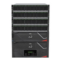
Fujitsu ETERNUS DX900 S6 Design Manual (243 pages)
Brand:
Fujitsu
| Category:
Storage
| Size: 25 MB
Table of Contents
Table of Contents
2
List of Figures
8
List of Tables
12
About this Manual
15
Intended Audience
15
Related Information and Documents
15
Document Conventions
16
Notice Symbols
16
Warning Signs
16
Overview
18
Product Lineup
18
Figure 1 Configuration Example for each ETERNUS DX
18
Eternus Dx600 S6
19
Table 1 Specifications (ETERNUS DX600 S6)
19
Eternus Dx900 S6
20
Table 2 Specifications (ETERNUS DX900 S6)
20
Function Specification List
22
Basic Functions
22
Table 3 Basic Functions
22
Table 4 Expansion Functions
23
Basic Functions
24
RAID Functions
24
Supported RAID
24
Table 5 RAID Level Comparison
25
User Capacity (Logical Capacity)
26
Table 6 Formula for Calculating User Capacity for each RAID Level
26
User Capacity of Drives
26
Table 7 User Capacity Per Drive
26
RAID Group
27
Table 8 RAID Group Types and Usage
27
Figure 2 Example of a RAID Group
28
Table 9 Number of Drives to Configure and the Recommended Number of Drives Per RAID
28
Volume
30
Figure 3 Volume Concept
30
Table 10 Number of Volumes that Can be Created
30
Table 11 Volumes that Can be Created
30
Hot Spare
32
Figure 4 Hot Spare
32
Table 12 Number of Installable Hot Spares (1/3)
33
Table 13 Number of Installable Hot Spares (2/3)
33
Table 14 Number of Installable Hot Spares (3/3)
33
Figure 5 Hot Spare Selection Criteria (for the ETERNUS DX600 S6)
34
Table 15 Hot Spare Selection Criteria - Search Order for Drive Enclosures (ETERNUS DX600 S6)
34
Table 16 Hot Spare Selection Criteria - Drives (ETERNUS DX600 S6)
34
Table 17 Hot Spare Selection Criteria - Search Order for Drive Enclosures (ETERNUS DX900 S6)
35
Table 18 Hot Spare Selection Criteria - Drives (ETERNUS DX900 S6)
35
Figure 6 Hot Spare Selection Criteria - Search Order for Drive Enclosures (ETERNUS DX900 S6, Example 1)
36
Figure 7 Hot Spare Selection Criteria - Search Order for Drive Enclosures (ETERNUS DX900 S6, Example 2)
36
Data Protection
37
Data Block Guard
37
Figure 8 Data Block Guard
37
Disk Drive Patrol
38
Figure 9 Disk Drive Patrol
38
Redundant Copy
39
Figure 10 Redundant Copy Function
39
Rebuild
40
Figure 11 Rebuild
40
Fast Recovery
41
Figure 12 Fast Recovery
41
Copyback/Copybackless
42
Figure 13 Copyback
42
Figure 14 Copybackless
43
Protection (Shield)
44
Figure 15 Protection (Shield)
44
Reverse Cabling
46
Figure 16 Reverse Cabling (for ETERNUS DX600 S6)
46
Operations Optimization (Virtualization/Automated Storage Tiering Control)
47
Thin Provisioning
47
Table 19 Maximum Pool Capacity and Required Number of Drives
48
Figure 17 Storage Capacity Virtualization
49
Table 20 TPP Maximum Number and Capacity
49
Table 21 Chunk Size According to the Configured TPP Capacity
50
Table 22 Levels and Configurations for a RAID Group that Can be Registered in a TPP
50
Table 23 TPP Thresholds
51
Table 24 TPV Thresholds
51
Figure 18 TPV Balancing (When Allocating Disproportionate TPV Physical Capacity Evenly)
53
Figure 19 TPV Balancing (When Distributing Host Accesses Evenly after TPP Expansion)
53
Figure 20 TPV/FTV Capacity Optimization
55
Flexible Tier
56
Automated Storage Tiering
56
Table 25 Chunk Size and Data Transfer Unit
56
Figure 21 Flexible Tier
57
Figure 22 FTV Configuration
57
Table 26 the Maximum Number and the Maximum Capacity of Ftsps
58
Table 27 Levels and Configurations for a RAID Group that Can be Registered in an FTSP
58
Table 28 FTRP Thresholds
59
Table 29 FTV Thresholds
59
Figure 23 FTRP Balancing
60
Extreme Cache Pool
61
Figure 24 Extreme Cache Pool
61
Optimization of Volume Configurations
62
Table 30 Maximum Installed Number of Extreme Cache Pools and Their Maximum Capacity
62
Table 31 Optimization of Volume Configurations
62
RAID Migration
64
Figure 25 RAID Migration (When Data Is Migrated to a High Capacity Drive)
64
Figure 26 RAID Migration (When a Volume Is Moved to a Different RAID Level)
64
Figure 27 RAID Migration
65
Logical Device Expansion
66
Figure 28 Logical Device Expansion (When Expanding the RAID Group Capacity)
66
Figure 29 Logical Device Expansion (When Changing the RAID Level)
66
LUN Concatenation
68
Figure 30 LUN Concatenation
68
Figure 31 LUN Concatenation (Volume Concatenation)
69
Wide Striping
70
Figure 32 Wide Striping
70
Data Encryption
71
Encryption with Self Encrypting Drive (SED)
72
Figure 33 Data Encryption with Self Encrypting Drives (SED)
72
Firmware Data Encryption
73
Figure 34 Firmware Data Encryption
73
User Access Management
75
Account Management
75
Figure 35 Account Management
75
Table 32 Number of Users that Can Simultaneously Log in to the Storage System
75
Table 33 Available Functions for Default Roles
76
User Authentication
77
Table 34 Client Public Key (SSH Authentication)
77
Audit Log
79
Figure 36 Audit Log
79
Improving Host Connectivity
80
Host Affinity
80
Figure 37 Host Affinity
80
Figure 38 Associating Host Groups, CA Port Groups, and LUN Groups
81
Iscsi Security
82
Environmental Burden Reduction
83
Eco-Mode
83
Figure 39 Eco-Mode
83
Table 35 Eco-Mode Specifications
84
Power Consumption Visualization
87
Figure 40 Power Consumption Visualization
87
Operation Management/Device Monitoring
88
Operation Management Interface
88
Table 36 Features of the Operation Management Interfaces
89
Table 37 Comparison of Operation Management Interfaces (1/2)
90
Table 38 Comparison of Operation Management Interfaces (2/2)
90
Performance Information Management
91
Event Notification
93
Figure 41 Event Notification
93
Table 39 Levels and Contents of Events that Are Notified
93
Simple Network Management Protocol (Snmp)
94
Table 40 SNMP Specifications
94
Host Sense
94
Device Time Synchronization
95
Figure 42 Device Time Synchronization
95
Remote Support
96
Power Control
96
Remote Power Operation (Wake on LAN)
96
Figure 43 Wake on LAN
96
Backup (Advanced Copy)
97
Figure 44 Example of Advanced Copy
97
Table 41 Control Software (Advanced Copy)
97
Table 42 List of Advanced Copy Specifications
98
Backup
99
Local Copy
99
Table 43 Characteristics of Snapopc/Snapopc+ Operations with each Type of Copy Destination Logical Volume
100
Remote Copy
102
Table 44 REC Data Transfer Mode
103
Asynchronous Transfer Mode
103
Figure 46 Restore OPC
106
Figure 47 EC or REC Reverse
106
Figure 48 Targets for the Multi-Copy Function
107
Figure 49 Multi-Copy
107
Figure 50 Multi-Copy (Including Snapopc+)
107
Figure 53 Multi-Copy
107
Figure 51 Multi-Copy (Using the Consistency Mode)
108
Figure 52 Multi-Copy
109
Figure 54 Cascade Copy
109
Table 45 Available Cascade Copy Combinations (When a Cascade Copy Performs Session 1 Followed by Session 2)
110
Table 46 Modified Data Size for each Quickopc Resolution
110
Table 47 Available Cascade Copy Combinations (When a Cascade Copy Performs Session 2 Followed by Session 1)
111
Figure 55 Cascade Copy (Using Three Copy Sessions)
113
Figure 56 Cascade Copy (Using Four Copy Sessions)
113
Figure 57 Cascade Copy (Adding a Different Copy Session to the Copy Source for Cascade Copy)
113
Figure 45 REC
114
Figure 58 Cascade Copy (Adding a Different Copy Session between Two Sets of Copy Sessions)
114
Figure 59 Cascade Copy (Cascade Copy with a Session Status Change)
114
Figure 60 OPC Restoration from the Cascade State
115
Figure 61 EC/REC Reverse from the Cascade State (1)
115
Figure 62 EC/REC Reverse from the Cascade State (2)
116
Table 48 Restrictions on the Availability of OPC Restoration or EC/REC Reverse During Cascade Copy (1/2)
116
Figure 63 Cascade Copy (Inversion of Cascade Copy 1)
117
Table 49 Restrictions on the Availability of OPC Restoration or EC/REC Reverse During
117
Figure 64 Cascade Copy (Inversion of Cascade Copy 2)
118
Figure 65 Mixture of Cascade Copy and Multi-Copy
119
Performance Tuning
120
Assigned Cms
120
Figure 66 Assigned Cms
120
Table 50 Auto Assignment of Assigned Cms (for 2 Cms)
120
Striping Size Expansion
121
Table 51 Auto Assignment of Assigned Cms (for 4 Cms)
121
Expansion Functions
122
Operations Optimization (Deduplication/Compression)
122
Deduplication/Compression
122
Figure 67 Deduplication/Compression Overview
123
Figure 68 Deduplication Overview
124
Figure 69 Compression Overview
124
Table 52 Deduplication/Compression Function Specifications (ETERNUS DX600 S6)
125
Table 53 Compression Function Specifications (ETERNUS DX900 S6)
125
Configuration Method
126
Table 54 Method for Enabling the Deduplication/Compression Function
126
Table 55 Volumes that Are to be Created Depending on the Selection of "Deduplication" and "Compression
127
Table 56 Deduplication/Compression Setting for Tpps Where the Target Volumes Can be Created
128
Figure 70 Details of the Deduplication/Compression Function
130
Table 57 Management Functions for Deduplication/Compression Volumes
131
User Access Management
132
Multitenancy
132
Figure 71 Multitenancy Operations
132
Stable Operation
133
Quality of Service (Qos)
133
Figure 72 Qos
133
Figure 73 Copy Path Bandwidth Limit
134
Host Response
135
Figure 74 Host Response
135
Storage Cluster
136
Figure 75 Storage Cluster (A/S Mode)
136
Figure 76 Storage Cluster (A/A Mode)
137
Figure 77 Mapping Tfovs, TFO Groups, and CA Port Pairs
137
Table 58 Storage Cluster Function Specifications
139
Data Migration
141
Storage Migration
141
Figure 78 Storage Migration
141
Non-Disruptive Storage Migration
143
Figure 79 Non-Disruptive Storage Migration
143
Table 59 Specifications for Paths and Volumes between the Local Storage System and the
143
Server Linkage Functions
145
Vmware Linkage
145
Figure 80 Vmware Linkage
145
Figure 81 VVOL (Operational Configuration)
147
Figure 82 VVOL (System Configuration)
148
Table 60 Maximum VVOL Capacity
148
Table 61 VVOL Management Information Specifications
149
Veeam Storage Integration
150
Figure 83 Veeam Storage Integration
150
Table 62 Volume Types that Can be Used with Veeam Storage Integration
152
Microsoft Linkage
153
Figure 84 Microsoft Linkage
153
Windows Server
154
Openstack Linkage
154
Logical Volume Manager (LVM)
155
Figure 85 Logical Volume Manager (LVM)
155
Connection Configuration
156
Power Supply Connection
156
Input Power Supply Lines
156
UPS Connection
156
Power Synchronized Connections
157
Power Synchronized Connections (Wake on LAN)
157
Figure 86 Power Supply Control Using Wake on LAN
157
LAN Connection
158
LAN for Operation Management
158
Figure 87 Connection Example Without a Dedicated Remote Support Port
159
Figure 88 Connection Example When the IP Address of the Sub CM Is Set (and a Dedicated Remote Support Port Is Not Used)
159
LAN for the Remote Reporting Service
160
Figure 89 Connection Example with a Dedicated Remote Support Port
160
Connection Configurations
160
Figure 90 Connection Example When the IP Address of the Sub CM Is Set (and a Dedicated Remote Support Port Is Used)
161
LAN Control (Main CM/Sub CM)
162
Figure 91 LAN Control (ETERNUS DX600 S6, Switching of the Main CM)
162
Figure 92 LAN Control (ETERNUS DX900 S6, Switching of the Main CM)
163
Figure 93 LAN Control (for ETERNUS DX600 S6, When the IP Address of the Sub CM Is Set)
164
Figure 94 LAN Control (for ETERNUS DX900 S6, When the IP Address of the Sub CM Is Set)
164
Network Communication Protocols
165
Table 63 LAN Port Availability
165
SAN Connection
167
Host Interface
167
Table 64 Ethernet Frame Capacity (Jumbo Frame Settings)
168
Access Method
169
Figure 95 Single Path Connection (When a SAN Connection Is Used - Direct Connection)
169
Figure 96 Single Path Connection (When a SAN Connection Is Used - Switch Connection)
169
Multipath Configuration
170
Figure 97 Multipath Connection
170
Figure 98 Multipath Connection (When a SAN Connection Is Used - Switch Connection)
170
Figure 99 Multipath Connection (When a SAN Connection Is Used for Enhanced Performance)
171
Remote Connections
172
Figure 100 Example of Non-Supported Connection Configuration (When Multiple Types of Remote Interfaces Are Installed in the same ETERNUS AF/DX)
172
Figure 101 Example of Supported Connection Configuration (When Multiple Types of Remote Interfaces Are Installed in the same ETERNUS AF/DX)
172
Remote Interfaces
173
Figure 102 an FC Connection for a Remote Copy between ETERNUS AF/DX Storage Systems (When Redundant Paths Are Used)
173
Figure 103 an FC Connection for a Remote Copy between ETERNUS AF/DX Storage Systems (When Lines Are Used)
173
Connectable Models
174
Figure 104 an Iscsi Connection for a Remote Copy between ETERNUS AF/DX Storage
174
Table 65 Connectable Models and Available Remote Interfaces
174
Hardware Configurations
175
Configuration Schematics
175
Maximum Configuration
175
Figure 105 ETERNUS DX600 S6 Maximum Configuration
175
Figure 106 ETERNUS DX900 S6 Maximum Configuration
176
Enclosure Connection Path
177
Figure 107 Enclosure Connection Paths (ETERNUS DX600 S6)
177
Figure 108 Enclosure Connection Paths (ETERNUS DX900 S6)
178
Frontend Enclosure
179
Eternus Dx900 S6
179
Figure 109 Front View of a Frontend Enclosure (with a Front Cover)
179
Figure 110 Front View of a Frontend Enclosure (Without a Front Cover)
180
Figure 111 Rear View of a Frontend Enclosure
180
Component
181
Figure 112 System Operation Panel
181
Figure 113 Service Controllers
181
Figure 114 Power Supply Units (Frontend Enclosure)
182
Figure 115 Frontend Routers (FRT)
182
Figure 116 Fan Unit
182
Controller Enclosure
183
Eternus Dx600 S6
183
Figure 117 Front View of a Controller Enclosure (for ETERNUS DX600 S6, with a Front Cover)
183
Figure 118 Front View of a Controller Enclosure (for ETERNUS DX600 S6, Without a Front Cover)
183
Figure 119 Rear View of a Controller Enclosure (ETERNUS DX600 S6)
184
Eternus Dx900 S6
185
Figure 120 Front View of a Controller Enclosure (for ETERNUS DX900 S6, with a Front Cover)
185
Figure 121 Front View of a Controller Enclosure (for ETERNUS DX900 S6, Without a Front Cover)
185
Figure 122 Rear View of a Controller Enclosure (ETERNUS DX900 S6)
186
Controllers
187
Table 66 Maximum System Memory Capacity for each Controller
187
Figure 123 Host Interface Ports
188
Table 67 Maximum Number of Host Interfaces Per Controller
188
Table 68 Host Interface Specifications
188
Figure 124 Drive Adapter
189
Table 69 Drive Interface Port Specification (Controller)
189
Table 70 MNT Port/Rmt Port/Fst Port Specifications
189
Component
190
Figure 125 Power Supply Units
190
Drive Enclosure
191
External Views of a Drive Enclosure
191
Figure 126 Front View of a 2.5" Nvme Type Drive Enclosure
191
Figure 127 Front View of a 2.5" SAS Type Drive Enclosure
191
Figure 128 Front View of a 3.5" SAS Type Drive Enclosure
192
Figure 129 Rear View of a 2.5" Nvme Type Drive Enclosure
192
Figure 130 Rear View of a 2.5"/3.5" Type Drive Enclosure (When Only One I/O Module Is Installed)
192
Component
193
Figure 131 Rear View of a 2.5"/3.5" Type Drive Enclosure (When Two I/O Modules Are Installed)
193
Figure 132 2.5" Nvme Type I/O Modules
193
Figure 133 2.5" SAS Type / 3.5" SAS Type I/O Modules
193
Figure 134 2.5" Nvme Type Power Supply Units
194
Table 71 Drive Interface Port Specification (I/O Module)
194
Figure 135 2.5" SAS Type / 3.5" SAS Type Power Supply Units
195
Table 72 2.5" Nvme SSD Specifications (2.5" Nvme Type Drive Enclosure)
195
Table 73 2.5" SAS Drive Specifications (2.5" SAS Type Drive Enclosure)
196
Table 74 3.5" SAS Drive Specifications (3.5" SAS Type Drive Enclosure)
196
Power Distribution Units
197
Figure 136 Power Distribution Unit (AC24A/200V, 2U, 16 Outlets)
197
Table 75 Power Distribution Unit (AC24A/200V, 2U, 16 Outlets) and Provided Power Cord Specifications
197
Figure 137 Power Distribution Unit (AC16A/200V, 2U, 16 Outlets)
198
Table 76 Power Distribution Unit (AC16A/200V, 2U, 16 Outlets) and Provided Power Cord Specifications
198
Figure 138 Power Distribution Unit (AC8A/200V, 1U, 4 Outlets)
199
Table 77 Power Distribution Unit (AC8A/200V, 1U, 4 Outlets) and Provided Power Cord Specifications
199
Installation Conditions and Standard Installation Rules
200
Controller Enclosures
200
System Memory
200
Table 78 Estimated System Memory Capacity of each Storage System (ETERNUS DX600 S6 with the Deduplication/Compression Function Disabled)
201
Table 79 Estimated System Memory Capacity of each Storage System (ETERNUS DX600 S6 with the Deduplication/Compression Function Enabled)
201
Table 80 Estimated System Memory Capacity of each Controller Enclosure (ETERNUS DX900 S6 with the Compression Function Disabled)
202
Table 81 Estimated System Memory Capacity of each Controller Enclosure (ETERNUS DX900 S6 with the Compression Function Enabled)
202
Host Interface
203
Installation Order
204
Figure 139 Host Interface Installation Diagram (ETERNUS DX600 S6)
204
Figure 140 Host Interface Installation Diagram (ETERNUS DX900 S6)
205
Drive Adapters
206
Figure 141 Drive Adapter Installation Diagram (ETERNUS DX600 S6)
206
Figure 142 Host Interface Installation Diagram (ETERNUS DX900 S6)
206
Drive Enclosure
207
Table 82 Number of Installable Drive Enclosures
207
Table 83 Maximum Number of Drive Slots
207
Drive
208
Table 84 SSD Characteristics and Specification Differences
210
Table 85 Drive Characteristics
211
Table 86 Number of Installable Drives
212
Table 87 Required Number of Drives to be Installed and Their Slot Locations
212
Figure 143 Installation Diagram for 2.5" Nvme Drives
214
Figure 144 Installation Diagram for 2.5" Drives
215
Figure 145 Installation Diagram for 3.5" Drives
215
Recommended RAID Group Configuration
216
Figure 146 Drive Combination 1
216
Figure 147 Drive Combination 2
217
Figure 148 Drive Combination 3
217
Figure 149 Drive Combination 4
218
Figure 150 Drive Combination 5
218
Figure 151 Recommended RAID1/RAID1+0 Configuration Example
219
Figure 152 Recommended RAID5/RAID5+0/RAID6 Configuration Example
220
Figure 153 Recommended RAID6-FR Configuration Example
221
Maintenance/Expansion
222
Hot Swap/Hot Expansion
222
Eternus Dx600 S6
222
Table 88 Hot Swap and Hot Expansion Availability for Components (ETERNUS DX600 S6)
222
Eternus Dx900 S6
223
Table 89 Hot Swap and Hot Expansion Availability for Components
223
Drive Sanitization
225
Release Information
226
Firmware Release Information
226
Table 90 Table
226
Specifications
227
Operating Environment
227
Supported Oss
227
Function Specifications
227
Volume Specifications
227
Table 91 Volume Specifications
227
OPC Specification
228
Figure 154 OPC Physical Copy
228
REC Specification
231
Table 92 REC Data Transfer Mode (1/2)
231
Table 93 REC Data Transfer Mode (2/2)
231
Figure 155 Update Information Management between ETERNUS DX Storage Systems
233
Figure 156 Copy Operation When All Copy Paths Are Blocked
235
Function Specification List
236
List of Supported Protocols
236
Table 94 List of Supported Protocols
236
List of Target Pools and Volumes for each Function
237
Target RAID Groups/Pools of each Function
237
Table 95 Target RAID Groups/Pools of each Function
237
Target Volumes of each Function
238
Table 96 Target Volumes of each Function
238
Combinations of Functions that Are Available for Simultaneous Executions
240
Table 97 Combinations of Functions that Can be Executed Simultaneously (1/2)
240
Table 98 Combinations of Functions that Can be Executed Simultaneously (2/2)
241
Number of Processes that Can be Executed Simultaneously
242
Capacity that Can be Processed Simultaneously
242
Advertisement
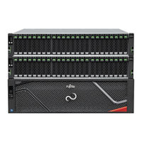
Fujitsu ETERNUS DX900 S6 Operation Manual (40 pages)
Brand:
Fujitsu
| Category:
Storage
| Size: 6 MB
Table of Contents
Table of Contents
2
List of Figures
4
List of Tables
5
About this Manual
6
Intended Audience
6
Related Information and Documents
7
Document Conventions
7
Warning Signs
8
Basic Operation
10
How to Open/Close the Rack Doors
10
How to Open/Close the Front Door
10
How to Open/Close the Rear Door
11
Powering on and off
12
Switching on and off the Main Line Switch on the Power Distribution Unit
12
Figure 1 on Position of the Main Line Switches on a 1U Power Distribution Unit
12
Figure 2 on Position of the Main Line Switches on a 2U Power Distribution Unit
13
Figure 3 off Position of the Main Line Switches on a 1U Power Distribution Unit
13
Figure 4 off Position of the Main Line Switches on a 2U Power Distribution Unit
14
Switching on and off the PSU Switch on the Power Supply Unit
15
Figure 5 on Position (Marked "|") of the PSU Switch on a Power Supply Unit
15
Figure 6 POWER LED on the Power Supply Unit
15
Figure 7 off Position (Marked "¡") of the PSU Switch of a Power Supply Unit
16
Powering on
17
Table 1 Time Required to Turn the Power on (When each Controller Is Installed with the Maximum System Memory Capacity)
17
Figure 8 LCD Panel Messages When Turning on the Power
20
Powering off
21
Table 2 Time Required to Turn the Power off
21
Figure 9 LCD Panel Messages When Turning off the Power
23
Using the Multifunction Switch (Setting Change Switch)
24
Storage System Monitoring
26
Checking LED Status
26
Checking the Message of the LCD Panel
26
Displaying Status Via ETERNUS Web GUI
26
Figure 10 ETERNUS Web GUI Screen
26
Displaying Status Via ETERNUS CLI
27
Table 3 General Status of ETERNUS Web GUI
27
Table 4 General Status of ETERNUS CLI
27
Event Notification
28
Audit Log
28
Process Time (Estimated)
29
Volume Formatting Time
29
Rebuild/Copyback Process Time
29
Table 5 Volume Formatting Time
29
Table 6 Rebuild Process Time
29
Table 7 Copyback Process Time
30
Expansion Functions
31
License Registration
31
Maintenance
32
Periodic Backup
32
Maintenance Service
32
Maintenance Support Period
32
Replacing Batteries
33
Related Service
33
Figure 11 Battery Unit Replacement Notification
33
Troubleshooting
34
Check List
34
Table 8 Time Required for the READY LED to Turns on after Turning the Power on
35
Required Information for Inquiries
38
Component Names
39
Advertisement
Related Products
Fujitsu Eternus DX90
Fujitsu Eternus DX90 S2
Fujitsu ETERNUS DX900 S5
Fujitsu Eternus DX440 S2
Fujitsu ETERNUS DX60 S4
Fujitsu ETERNUS DX440
Fujitsu ETERNUS DX8000 S2 Series
Fujitsu ETERNUS DX500 S3/DX600 S3
Fujitsu ETERNUS DX600 S5
Fujitsu ETERNUS DX S6 Series
Fujitsu Categories
Air Conditioner
Laptop
Server
Scanner
Storage
More Fujitsu Manuals
Login
Sign In
OR
Sign in with Facebook
Sign in with Google
Upload manual
Upload from disk
Upload from URL