
Related Manuals for Kuka KR SCARA-2


Summary of Contents for Kuka KR SCARA-2
- Page 1 Robots KR SCARA-2 Specification Issued: 18.08.2021 Spez KR SCARA-2 V1 KUKA Robotics Guangdong...
- Page 2 China This documentation or excerpts therefrom may not be reproduced or disclosed to third parties without the express permission of KUKA Robotics Guangdong Co., Ltd. Other functions not described in this documentation may be operable in the controller. The user has no claims to these functions, however, in the case of a replacement or service work.
-
Page 3: Table Of Contents
REACH duty to communicate information acc. to Art. 33........Stopping distances and times................4.7.1 General information....................4.7.2 Stopping distances and times, KR 6 R500 Z200-2..........4.7.2.1 Stopping distances and stopping times for STOP 0, A1 to A3......Spez KR SCARA-2 V1 | Issued: 18.08.2021 www.kuka.com | 3/68... - Page 4 6.1.3 Transporting via fork lift truck................6.1.4 Transporting via people..................Appendix....................Tightening torques....................Auxiliary and operating materials used..............Applied standards and regulations............... KUKA Service................... Requesting support....................KUKA Customer Support..................Index 4/68 | www.kuka.com Spez KR SCARA-2 V1 | Issued: 18.08.2021...
-
Page 5: Introduction
• Facilitation of verification and testing • Procedure for documenting source code For optimal use of KUKA products, we recommend the training courses offered by KUKA College. Information about the training program can be found at www.kuka.com or can be obtained directly from our subsidia- ries. -
Page 6: Terms Used
Stopping distance = reaction distance + braking distance The stopping distance is part of the danger zone. Workspace Area within which the robot may move. The workspace is derived from the individual axis ranges. 6/68 | www.kuka.com Spez KR SCARA-2 V1 | Issued: 18.08.2021... - Page 7 Program override (%) = velocity of the robot motion. This value can be entered in the controller via the teach pendant, from which it can be read. Spez KR SCARA-2 V1 | Issued: 18.08.2021 www.kuka.com | 7/68...
- Page 8 Test mode, Manual High Velocity (> 250 mm/s permissible) External axis Motion axis which is not part of the manipulator but is controlled by the robot controller, e.g. KUKA linear unit, turn-tilt table, positioner. 8/68 | www.kuka.com Spez KR SCARA-2 V1 | Issued: 18.08.2021...
-
Page 9: Product Description
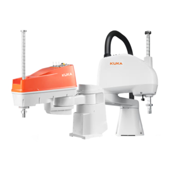
KR SCARA-2 Product description Overview of the robot system Description The Product Family KR SCARA-2 has the following 2 types of manipula- tors: • KR 6 R500 Z200-2 • KR 6 R700 Z200-2 The robot system (>>> Fig. 2-1) of this product family has the following parts: •... -
Page 10: Description Of The Manipulator
2.2.4 "Link arm" Page Base frame (>>> 2.2.3 "Base frame" Page Link arm (>>> 2.2.4 "Link arm" Page Options The robot can, for example, be equipped with the following option. • End flange 10/68 | www.kuka.com Spez KR SCARA-2 V1 | Issued: 18.08.2021... -
Page 11: Arm
• Data cables • I/O cables • Gas pipes These cables are for the control of axis 2, axis 3, axis 4, and other elec- tric elements on the arm. Spez KR SCARA-2 V1 | Issued: 18.08.2021 www.kuka.com | 11/68... -
Page 12: Base Frame
Description The interface of electrical installation To connect the manipulator to the robot controller via the con- necting cables. (>>> 5.3 "Connecting cables and interfaces" Page Base frame Rotational axis 12/68 | www.kuka.com Spez KR SCARA-2 V1 | Issued: 18.08.2021... -
Page 13: Link Arm
Any use or application deviating from the intended use is deemed to be misuse and is not allowed. It will result in the loss of warranty and liability claims. KUKA is not liable for any damage due to such misuse. This in- cludes e.g.: •... - Page 14 KR SCARA-2 The robot system is an integral part of a complete system and may only be operated in a CE-compliant system. 14/68 | www.kuka.com Spez KR SCARA-2 V1 | Issued: 18.08.2021...
-
Page 15: Safety
• This “Safety” chapter refers to a mechanical component of an indus- trial robot. • If the mechanical component is used together with a KUKA robot controller, the “Safety” chapter of the operating instructions or as- sembly instructions of the robot controller must be used! This contains all the information provided in this “Safety”... -
Page 16: Ec Declaration Of Conformity And Declaration Of Incorporation
Area within which the robot may move. The workspace is derived from the individual axis ranges. User The user of the industrial robot can be the management, employer or delegated person responsible for use of the industrial robot. 16/68 | www.kuka.com Spez KR SCARA-2 V1 | Issued: 18.08.2021... - Page 17 For robot controllers of the KR C5 series, only the model “smart- PAD-2” is used. For other robot controllers, the designation “KUKA smartPAD” or “smartPAD” always refers to both models unless an explicit distinc- tion is made.
-
Page 18: Personnel
Test mode, Manual High Velocity (> 250 mm/s permissible) External axis Motion axis which is not part of the manipulator but is controlled by the robot controller, e.g. KUKA linear unit, turn-tilt table, positioner. Personnel The following persons or groups of persons are defined for the industrial robot: •... -
Page 19: Workspace, Safety Zone And Danger Zone
If there are no physical safeguards present, the requirements for collabo- rative operation in accordance with EN ISO 10218 must be met. Overview of protective equipment The protective equipment of the mechanical component may include: • Mechanical end stops Spez KR SCARA-2 V1 | Issued: 18.08.2021 www.kuka.com | 19/68... -
Page 20: Mechanical End Stops
Death, injuries or damage to property may re- sult. • Put manipulator out of operation. • KUKA must be consulted before it is put back into operation. 3.4.2 Mechanical axis limitation (optional) Some manipulators can be fitted with adjustable mechanical axis limitation systems in axes A1 to A3. -
Page 21: Labeling On The Industrial Robot
Incorrect installation (e.g. overload) or mechanical defects (e.g. brake de- fect) can cause the manipulator or external axes to sag. If work is to be carried out on a switched-off industrial robot, the manipulator and external Spez KR SCARA-2 V1 | Issued: 18.08.2021 www.kuka.com | 21/68... - Page 22 PADs/KCPs being interchanged. Death, injuries or damage to property may result. • Remove the disconnected smartPAD/KCP from the system immedi- ately. • Store the disconnected smartPAD/KCP out of sight and reach of personnel working on the industrial robot. 22/68 | www.kuka.com Spez KR SCARA-2 V1 | Issued: 18.08.2021...
-
Page 23: Transportation
Transportation must be carried out in accordance with the operating in- structions or assembly instructions of the robot controller. Avoid vibrations and impacts during transportation in order to prevent damage to the robot controller. Spez KR SCARA-2 V1 | Issued: 18.08.2021 www.kuka.com | 23/68... -
Page 24: Start-Up And Recommissioning
KR SCARA-2 External axis (optional) The prescribed transport position of the external axis (e.g. KUKA linear unit, turn-tilt table, positioner) must be observed. Transportation must be carried out in accordance with the operating instructions or assembly in- structions of the external axis. -
Page 25: Manual Mode
• All setup work must be carried out, where possible, from outside the safeguarded area. Spez KR SCARA-2 V1 | Issued: 18.08.2021 www.kuka.com | 25/68... -
Page 26: Automatic Mode
GENCY STOP has been triggered. 3.5.6 Maintenance and repair After maintenance and repair work, checks must be carried out to ensure the required safety level. The valid national or regional work safety regula- 26/68 | www.kuka.com Spez KR SCARA-2 V1 | Issued: 18.08.2021... - Page 27 Voltages in excess of 50 V (up to 780 V) can be present in various com- ponents for several minutes after the robot controller has been switched off! To prevent life-threatening injuries, no work may be carried out on the industrial robot in this time. Spez KR SCARA-2 V1 | Issued: 18.08.2021 www.kuka.com | 27/68...
-
Page 28: Decommissioning, Storage And Disposal
Use current safety data sheets Knowledge of the safety data sheets of the substances and mixtures used is a prerequisite for the safe use of KUKA products. Death, injuries or damage to property may otherwise result. • Request up-to-date safety data sheets from the manufacturers of hazardous substances regularly. -
Page 29: Technical Data
XF21 - X15/X18 Ground conductor / equi- Ring cable lug potential bonding (can be ordered as an option) Cable lengths Standard For detailed specifications of the connecting cables, see . Spez KR SCARA-2 V1 | Issued: 18.08.2021 www.kuka.com | 29/68... -
Page 30: Axis Data Overview
Mastering posi- Mastering posi- Mastering posi- Designation tion A1 tion A2 tion A3 tion A4 KR 6 R500 Z200-2 0 ° 0 ° -4 mm -90 ° KR 6 R700 Z200-2 30/68 | www.kuka.com Spez KR SCARA-2 V1 | Issued: 18.08.2021... - Page 31 The following diagrams show the shape and size of the working envelope for these variants of this product family. Working envelope, KR 6 R500 Z200-2 Fig. 4-2: KR 6 R500 Z200-2, working envelope, overall Spez KR SCARA-2 V1 | Issued: 18.08.2021 www.kuka.com | 31/68...
-
Page 32: Payloads Overview
Maximum pay- Rated payload plementary moment of iner- load load, arm tia for flange Ix KR 6 R500 Z200-2 3 kg 6 kg 1 kg 0.01 kgm² KR 6 R700 Z200-2 32/68 | www.kuka.com Spez KR SCARA-2 V1 | Issued: 18.08.2021... - Page 33 KR SCARA-2 Load center of gravity and mass moment of inertia Fig. 4-4: Load center of gravity Payload diagram, KR 6 R500 Z200-2 Fig. 4-5: KR 6 R500 Z200-2, payload diagram Spez KR SCARA-2 V1 | Issued: 18.08.2021 www.kuka.com | 33/68...
- Page 34 With reduced load cen- ter distances, higher loads up to the maximum payload may be used. The specific load case must be verified using KUKA.Load. For further consulta- tion, please contact KUKA Support.
- Page 35 The EMERGENCY STOP values may arise in the event of an Emergency Stop situation of the robot. As these should only occur very rarely during the service life of the robot, a static strength verification is usually suffi- cient. Spez KR SCARA-2 V1 | Issued: 18.08.2021 www.kuka.com | 35/68...
- Page 36 The dimensions and the installa- tion position are specified in the following diagram (>>> Fig. 4-9). The maximum load must be noticed for mounting the supplementary load. 36/68 | www.kuka.com Spez KR SCARA-2 V1 | Issued: 18.08.2021...
-
Page 37: Foundation Loads Overview
(weight) of the manipulator. Fig. 4-10: Foundation loads Vertical force F(v) F(v normal) F(v max) KR 6 R500 Z200-2 295 N 517 N KR 6 R700 Z200-2 319 N 562 N Spez KR SCARA-2 V1 | Issued: 18.08.2021 www.kuka.com | 37/68... -
Page 38: Plates And Labels
The following plates and labels are attached to the manipulator. They must not be removed or rendered illegible. Illegible plates and labels must be replaced. Fig. 4-11: Location of plates and labels 38/68 | www.kuka.com Spez KR SCARA-2 V1 | Issued: 18.08.2021... - Page 39 Risk of injury! Work on the manipulator Before start-up, transportation or maintenance, read and follow the assembly and operating instructions. Spez KR SCARA-2 V1 | Issued: 18.08.2021 www.kuka.com | 39/68...
-
Page 40: Item Description
Council dated 18 December 2006 on the registration, evaluation and authorization of chemicals (REACH Regulation) is in force. Detailed REACH information can be found in the product information in KUKA Xpert. 40/68 | www.kuka.com Spez KR SCARA-2 V1 | Issued: 18.08.2021... -
Page 41: Stopping Distances And Times
• Program override POV = 100% • Mass m = rated load Stopping distance Stopping time Axis 1 39.26 ° 0.20 s Axis 2 66.92 ° 0.15 s Axis 3 65.19 mm 0.11 s Spez KR SCARA-2 V1 | Issued: 18.08.2021 www.kuka.com | 41/68... -
Page 42: Stopping Distances And Stopping Times, Stop 1, A1
KR SCARA-2 4.7.2.2 Stopping distances and stopping times, STOP 1, A1 Fig. 4-12: Stopping distances for STOP 1, axis 1 42/68 | www.kuka.com Spez KR SCARA-2 V1 | Issued: 18.08.2021... - Page 43 KR SCARA-2 Fig. 4-13: Stopping times for STOP 1, axis 1 Spez KR SCARA-2 V1 | Issued: 18.08.2021 www.kuka.com | 43/68...
-
Page 44: Stopping Distances And Stopping Times, Stop 1, A2
KR SCARA-2 4.7.2.3 Stopping distances and stopping times, STOP 1, A2 Fig. 4-14: Stopping distances for STOP 1, axis 2 Fig. 4-15: Stopping times for STOP 1, axis 2 44/68 | www.kuka.com Spez KR SCARA-2 V1 | Issued: 18.08.2021... -
Page 45: Stopping Distances And Stopping Times, Stop 1, A3
• Extension l = 100% • Program override POV = 100% • Mass m = rated load Stopping distance Stopping time Axis 1 75.00 ° 0.35 s Axis 2 69.59 ° 0.15 s Spez KR SCARA-2 V1 | Issued: 18.08.2021 www.kuka.com | 45/68... -
Page 46: Stopping Distances And Stopping Times, Stop 1, A1
KR SCARA-2 Stopping distance Stopping time Axis 3 85.92 mm 0.13 s 4.7.3.2 Stopping distances and stopping times, STOP 1, A1 Fig. 4-18: Stopping distances for STOP 1, axis 1 46/68 | www.kuka.com Spez KR SCARA-2 V1 | Issued: 18.08.2021... - Page 47 KR SCARA-2 Fig. 4-19: Stopping times for STOP 1, axis 1 Spez KR SCARA-2 V1 | Issued: 18.08.2021 www.kuka.com | 47/68...
-
Page 48: Stopping Distances And Stopping Times, Stop 1, A2
KR SCARA-2 4.7.3.3 Stopping distances and stopping times, STOP 1, A2 Fig. 4-20: Stopping distances for STOP 1, axis 2 Fig. 4-21: Stopping times for STOP 1, axis 2 48/68 | www.kuka.com Spez KR SCARA-2 V1 | Issued: 18.08.2021... -
Page 49: Stopping Distances And Stopping Times, Stop 1, A3
KR SCARA-2 4.7.3.4 Stopping distances and stopping times, STOP 1, A3 Fig. 4-22: Stopping distances for STOP 1, axis 3 Fig. 4-23: Stopping times for STOP 1, axis 3 Spez KR SCARA-2 V1 | Issued: 18.08.2021 www.kuka.com | 49/68... - Page 50 KR SCARA-2 50/68 | www.kuka.com Spez KR SCARA-2 V1 | Issued: 18.08.2021...
-
Page 51: Planning
16 mm thick. The flatness of the mounting base must be no more than 0.4. The mounting base is not in the supply scope of the robot system. Hole pattern The following holes must be used for mounting the manipulator. Spez KR SCARA-2 V1 | Issued: 18.08.2021 www.kuka.com | 51/68... -
Page 52: Connecting Cables And Interfaces
343 K (+70 °C). • The motor cables and the data cables must be separately routed in the respective metal ducts. Additional measures must be taken to en- sure electromagnetic compatibility (EMC). 52/68 | www.kuka.com Spez KR SCARA-2 V1 | Issued: 18.08.2021... -
Page 53: Interfaces
Additional axis connection Optional interface Data cable (X15/X18) Ground conductor connection Motor cable (XM1/XM2-4) Air connection AIR1 To connect to the gas source in the factory. • ø 4 mm Spez KR SCARA-2 V1 | Issued: 18.08.2021 www.kuka.com | 53/68... - Page 54 Effective for axis 1, axis 2, axis 3 and axis 4. When you press and hold down the brake release button, the brakes for axes are released. You can manually move the axes. 54/68 | www.kuka.com Spez KR SCARA-2 V1 | Issued: 18.08.2021...
-
Page 55: User Connectors
The following 2 types of I/O extension connectors are supplied for users to do extensions: • 9 pin • 15 pin User connectors Fig. 5-4: User connectors on the base frame 9 pin D-sub socket connector 15 pin D-sub socket connector Spez KR SCARA-2 V1 | Issued: 18.08.2021 www.kuka.com | 55/68... - Page 56 KR SCARA-2 Fig. 5-5: User connectors on the arm 15 pin D-sub socket connector 9 pin D-sub socket connector Wiring diagram of user connectors Fig. 5-6: Wiring diagram user connectors 56/68 | www.kuka.com Spez KR SCARA-2 V1 | Issued: 18.08.2021...
-
Page 57: Transportation
The transport dimensions for the manipulator without equipment can be noted from the following diagram (>>> Fig. 6-2). The position of the center of gravity and the weight vary according to the specific configuration. Spez KR SCARA-2 V1 | Issued: 18.08.2021 www.kuka.com | 57/68... -
Page 58: Transporting Via Fork Lift Truck
• Use authorized handling equipment with a sufficient load-bearing ca- pacity. Fig. 6-3: Transporting the package box 6.1.4 Transporting via people Description The manipulator can be transported by 2 people (>>> Fig. 6-4). 58/68 | www.kuka.com Spez KR SCARA-2 V1 | Issued: 18.08.2021... - Page 59 Personal injuries or property damage due to falling manipulator During transportation, a falling manipulator can cause personal injuries or property damage. • Carefully and slowly transport the manipulator. • Wear protective equipment. Fig. 6-4: Transporting via people Spez KR SCARA-2 V1 | Issued: 18.08.2021 www.kuka.com | 59/68...
- Page 60 KR SCARA-2 60/68 | www.kuka.com Spez KR SCARA-2 V1 | Issued: 18.08.2021...
-
Page 61: Appendix
0.8 Nm 1.9 Nm 1.9 Nm 3.8 Nm 3.8 Nm Strength class Thread 10.9 DIN7984 Pan head screws 2.8 Nm Tighten M5 domed cap nuts with a torque of 4.2 Nm. Spez KR SCARA-2 V1 | Issued: 18.08.2021 www.kuka.com | 61/68... -
Page 62: Auxiliary And Operating Materials Used
Directive 2014/30/EC of the European Parliament and of the Coun- cil dated 26 February 2014 on the approximation of the laws of the Member States concerning electromagnetic compatibility ANSI/RIA R15.06-2012 Industrial Robots and Robot System 62/68 | www.kuka.com Spez KR SCARA-2 V1 | Issued: 18.08.2021... - Page 63 EN ISO 13849-2:2012 Safety of machinery: Safety-related parts of control systems - Part 2: Validation NFPA 79:2018 Electrical Standard for Industrial Machinery UL 1740:2018 Robots and Robotic Equipment Spez KR SCARA-2 V1 | Issued: 18.08.2021 www.kuka.com | 63/68...
- Page 64 KR SCARA-2 64/68 | www.kuka.com Spez KR SCARA-2 V1 | Issued: 18.08.2021...
-
Page 65: Kuka Service
‒ System Software diagnosis package Additionally for KUKA Sunrise: Existing projects including applica- tions For versions of KUKA System Software older than V8: Archive of the software (Diagnosis package is not yet available here.) ‒ Application used ‒ External axes used... - Page 66 KR SCARA-2 66/68 | www.kuka.com Spez KR SCARA-2 V1 | Issued: 18.08.2021...
-
Page 67: Index
Linear unit............15 Link arm............13 EC declaration of conformity......16 Low Voltage Directive........16 EDS..............7 Electrical Standard for Industrial Machinery..63 Electromagnetic compatibility (EMC)..... 63 Electromagnetic compatibility (EMC):.... 63 EMC Directive.......... 16, 62 Spez KR SCARA-2 V1 | Issued: 18.08.2021 www.kuka.com | 67/68... - Page 68 Warnings............5 Regulations............. 62 Workspace........... 6, 16, 19 Release device..........21 Repair............. 26 Robot controller..........15 Safety..............15 Safety instructions..........5 Safety of machinery........63 Safety options..........17 Safety zone..........17, 19 68/68 | www.kuka.com Spez KR SCARA-2 V1 | Issued: 18.08.2021...
Need help?
Do you have a question about the KR SCARA-2 and is the answer not in the manual?
Questions and answers