
Subscribe to Our Youtube Channel
Related Manuals for Kuka IONTEC KR 20 R3100


Summary of Contents for Kuka IONTEC KR 20 R3100
- Page 1 Robots KR IONTEC With F Variants Assembly Instructions Issued: 11.05.2021 MA KR IONTEC V4 KUKA Deutschland GmbH...
- Page 2 Germany This documentation or excerpts therefrom may not be reproduced or disclosed to third parties without the express permission of KUKA Deutschland GmbH. Other functions not described in this documentation may be operable in the controller. The user has no claims to these functions, however, in the case of a replacement or service work.
-
Page 3: Table Of Contents
Axis data, KR 30 R2100..................4.3.3 Payloads, KR 30 R2100..................4.3.4 Foundation loads, KR 30 R2100................Technical data, KR 50 R2100................4.4.1 Basic data, KR 50 R2100..................4.4.2 Axis data, KR 50 R2100..................MA KR IONTEC V4 | Issued: 11.05.2021 www.kuka.com | 3/344... - Page 4 Stopping distances and times, KR 70 R2100 and KR 70 R2100 F....4.11.6.1 Stopping distances and stopping times, STOP 0, A1 to A3....... 4.11.6.2 Stopping distances and stopping times, STOP 1, A1.......... 4/344 | www.kuka.com MA KR IONTEC V4 | Issued: 11.05.2021...
- Page 5 Description of the connecting cables..............Description of overtravel protection on axis 4............Maintenance....................189 Maintenance overview................... 8.1.1 Maintenance table, KR IONTEC KR 20 R3100........... 8.1.2 Maintenance table, KR IONTEC standard and Foundry variants......Greasing cable set A1..................8.2.1 Checking and greasing cable set A1..............
- Page 6 Installing motor A3....................9.3.5 Mounting the cover....................9.3.6 Removing the equipment securing the in-line wrist and robot arm..... 9.3.7 Concluding work....................KR IONTEC Foundry.................... 9.4.1 Exchanging motor A1.................... 9.4.1.1 Removing motor A1....................6/344 | www.kuka.com MA KR IONTEC V4 | Issued: 11.05.2021...
- Page 7 Installing motor A5....................9.5.4.6 Installing motor A4....................9.5.4.7 Mounting the cover....................9.5.4.8 Removing the equipment securing the in-line wrist and robot arm..... 9.5.4.9 Concluding work....................Description of the electrical installations.............. MA KR IONTEC V4 | Issued: 11.05.2021 www.kuka.com | 7/344...
- Page 8 11.5.1.2 Concluding work....................Appendix....................335 12.1 Tightening torques....................12.2 Auxiliary and operating materials used..............12.3 Applied standards and regulations............... KUKA Service................... 339 13.1 Requesting support....................13.2 KUKA Customer Support..................Index 8/344 | www.kuka.com MA KR IONTEC V4 | Issued: 11.05.2021...
-
Page 9: Introduction
• Advanced knowledge of electrical engineering • Knowledge of the robot controller system For optimal use of KUKA products, we recommend the training courses offered by KUKA College. Information about the training program can be found at www.kuka.com or can be obtained directly from our subsidia- ries. -
Page 10: Terms Used
5. With parallelogram robots, the distance between axis 1 and the intersection of axis 6 and the mounting flange. Ceiling Clean Room Designation for KUKA products developed for use in cleanrooms. Electronic Data Storage (memory card) Electronic Mastering Device Spare parts package 10/344 | www.kuka.com... - Page 11 For the secondary foodstuffs industry High Protection Hollow Wrist Shelf-mounted KUKA Control Panel Teach pendant for the KR C2/KR C2 edition2005 The KCP has all the operator control and display functions required for operating and programming the industrial robot. KUKA robot...
- Page 12 For robot controllers of the KR C5 series, only the model “smart- PAD-2” is used. For other robot controllers, the designation “KUKA smartPAD” or “smartPAD” always refers to both models unless an explicit distinc- tion is made.
- Page 13 Test mode, Manual High Velocity (> 250 mm/s permissible) Wall Waterproof External axis Motion axis which is not part of the manipulator but is controlled by the robot controller, e.g. KUKA linear unit, turn-tilt table, positioner. MA KR IONTEC V4 | Issued: 11.05.2021 www.kuka.com | 13/344...
- Page 14 KR IONTEC 14/344 | www.kuka.com MA KR IONTEC V4 | Issued: 11.05.2021...
-
Page 15: Product Description
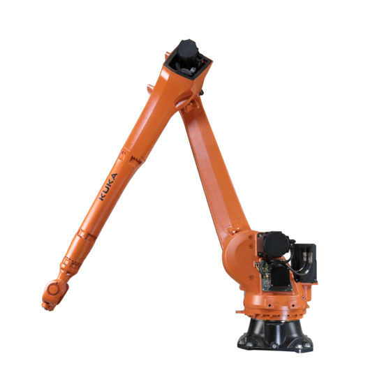
An industrial robot of this product family comprises the following compo- nents: • Manipulator • Connecting cables • Robot controller • Teach pendant (KUKA smartPAD) • Software • Options, accessories Fig. 2-1: Example of an industrial robot Manipulator Connecting cables... -
Page 16: Description Of The Manipulator
33). The in-line wrist is driven by the mo- tors inside the in-line wrist. There is an interface on the arm for fastening supplementary loads. The mounting flange conforms, with minimal deviations, to ISO 9409-1: 2004 16/344 | www.kuka.com MA KR IONTEC V4 | Issued: 11.05.2021... -
Page 17: Intended Use And Misuse
Intended use The industrial robot is intended for handling tools and fixtures or for pro- cessing and transferring components or products. Use is only permitted under the specified environmental conditions. MA KR IONTEC V4 | Issued: 11.05.2021 www.kuka.com | 17/344... - Page 18 Any use or application deviating from the intended use is deemed to be misuse and is not allowed. It will result in the loss of warranty and liability claims. KUKA is not liable for any damage resulting from such misuse. This includes e.g.: •...
-
Page 19: Safety
• This “Safety” chapter refers to a mechanical component of an indus- trial robot. • If the mechanical component is used together with a KUKA robot controller, the “Safety” chapter of the operating instructions or as- sembly instructions of the robot controller must be used! This contains all the information provided in this “Safety”... -
Page 20: Ec Declaration Of Conformity And Declaration Of Incorporation
Area within which the robot may move. The workspace is derived from the individual axis ranges. User The user of the industrial robot can be the management, employer or delegated person responsible for use of the industrial robot. 20/344 | www.kuka.com MA KR IONTEC V4 | Issued: 11.05.2021... - Page 21 For robot controllers of the KR C5 series, only the model “smart- PAD-2” is used. For other robot controllers, the designation “KUKA smartPAD” or “smartPAD” always refers to both models unless an explicit distinc- tion is made.
-
Page 22: Personnel
Test mode, Manual High Velocity (> 250 mm/s permissible) External axis Motion axis which is not part of the manipulator but is controlled by the robot controller, e.g. KUKA linear unit, turn-tilt table, positioner. Personnel The following persons or groups of persons are defined for the industrial robot: •... -
Page 23: Workspace, Safety Zone And Danger Zone
Overview of protective equipment The protective equipment of the mechanical component may include: • Mechanical end stops • Mechanical axis limitation (optional) • Release device (optional) • Brake release device (optional) MA KR IONTEC V4 | Issued: 11.05.2021 www.kuka.com | 23/344... -
Page 24: Mechanical End Stops
Death, injuries or damage to property may re- sult. • Put manipulator out of operation. • KUKA must be consulted before it is put back into operation. 3.4.2 Mechanical axis limitation (optional) Some manipulators can be fitted with adjustable mechanical axis limitation systems in axes A1 to A3. -
Page 25: Labeling On The Industrial Robot
If this is not possi- MA KR IONTEC V4 | Issued: 11.05.2021 www.kuka.com | 25/344... - Page 26 The external keyboard and/or external mouse must be removed from the control cabinet as soon as the start-up or maintenance work is completed or the KCP/smartPAD is connected. 26/344 | www.kuka.com MA KR IONTEC V4 | Issued: 11.05.2021...
-
Page 27: Transportation
External axis (optional) The prescribed transport position of the external axis (e.g. KUKA linear unit, turn-tilt table, positioner) must be observed. Transportation must be carried out in accordance with the operating instructions or assembly in- structions of the external axis. - Page 28 KR IONTEC The passwords for logging onto the KUKA System Software as “Expert” and “Administrator” must be changed before start-up and must only be communicated to authorized personnel. WARNING Danger to life and limb due to incorrectly assigned cables The robot controller is preconfigured for the specific industrial robot. The manipulator and other components can receive incorrect data if they are connected to a different robot controller.
-
Page 29: Manual Mode
• The operator must be positioned outside the danger zone. • There must be no other persons inside the safeguarded area. It is the responsibility of the operator to ensure this. MA KR IONTEC V4 | Issued: 11.05.2021 www.kuka.com | 29/344... -
Page 30: Automatic Mode
• Then check to ensure that the system is deenergized. • Inform the individuals involved that the robot controller is switched off. (e.g. by affixing a warning sign) 30/344 | www.kuka.com MA KR IONTEC V4 | Issued: 11.05.2021... - Page 31 • Inspection intervals in all other countries must be researched and ob- served. As a rule, however, at least the maintenance intervals speci- fied by KUKA must be observed. Shorter intervals are not permitted. The following safety measures must be carried out when working on the counterbalancing system: •...
-
Page 32: Decommissioning, Storage And Disposal
Use current safety data sheets Knowledge of the safety data sheets of the substances and mixtures used is a prerequisite for the safe use of KUKA products. Death, injuries or damage to property may otherwise result. • Request up-to-date safety data sheets from the manufacturers of hazardous substances regularly. -
Page 33: Technical Data
• Plates and labels (>>> 4.9 "Plates and labels" Page 126) • Stopping distances and stopping times (>>> 4.11.5 "Stopping distances and times, KR 50 R2500 and KR 50 R2500 F" Page 146) MA KR IONTEC V4 | Issued: 11.05.2021 www.kuka.com | 33/344... -
Page 34: Technical Data, Kr 20 R3100
603 mm x 480 mm Hole pattern: mounting surface for S400 kinematic system Permissible angle of inclination Default color Base frame: black (RAL 9005); Moving parts: KUKA Industrial Or- ange (RAL 2009) 34/344 | www.kuka.com MA KR IONTEC V4 | Issued: 11.05.2021... - Page 35 50 m Max. cable length 50 m Max. number of plug connections For detailed specifications of the connecting cables, see “Description of the connecting cables”. Certificates ESD requirements IEC61340-5-1; ANSI/ESD S20.20 MA KR IONTEC V4 | Issued: 11.05.2021 www.kuka.com | 35/344...
-
Page 36: Axis Data, Kr 20 R3100
Fig. 4-1: Direction of rotation of the axes Mastering positions Mastering position -9 ° -90 ° 90 ° 0 ° 0 ° 0 ° 36/344 | www.kuka.com MA KR IONTEC V4 | Issued: 11.05.2021... - Page 37 The reference point for the working envelope is the intersection of axes 4 and 5. Fig. 4-2: KR 20 R3100, working envelope, side view MA KR IONTEC V4 | Issued: 11.05.2021 www.kuka.com | 37/344...
- Page 38 The inclined installation angles must be individually checked and en- tered. An incorrectly entered inclined installation angle can lead to un- foreseen motion and/or to an overload and, potentially, damage to the robot. 38/344 | www.kuka.com MA KR IONTEC V4 | Issued: 11.05.2021...
-
Page 39: Payloads, Kr 20 R3100
Rated supplementary load, rotating 0 kg column Maximum supplementary load, ro- 50 kg tating column Rated supplementary load, link 0 kg Maximum supplementary load, link 30 kg Rated supplementary load, arm 20 kg MA KR IONTEC V4 | Issued: 11.05.2021 www.kuka.com | 39/344... - Page 40 Inertia about the Z axis of the main axis sys- and A, B, C unambiguously define the main axis system: • The origin of the main axis system is the center of mass. 40/344 | www.kuka.com MA KR IONTEC V4 | Issued: 11.05.2021...
- Page 41 (payload and mass moment of inertia) must be checked in all ca- ses. Exceeding this capacity will reduce the service life of the robot and overload the motors and the gears; in any such case KUKA Deutsch- land GmbH must be consulted beforehand.
- Page 42 The EMERGENCY STOP values may arise in the event of an Emergency Stop situation of the robot. As these should only occur very rarely during the service life of the robot, a static strength verification is usually suffi- cient. 42/344 | www.kuka.com MA KR IONTEC V4 | Issued: 11.05.2021...
- Page 43 When mounting the supplementary loads, be careful to observe the maxi- mum permissible total load. The dimensions and positions of the installa- tion options can be seen in the following diagrams. MA KR IONTEC V4 | Issued: 11.05.2021 www.kuka.com | 43/344...
- Page 44 KR IONTEC Fig. 4-9: KR 20 R3100, fastening of supplementary load, arm/in-line wrist 44/344 | www.kuka.com MA KR IONTEC V4 | Issued: 11.05.2021...
-
Page 45: Foundation Loads, Kr 20 R3100
F(h max) 8475 N M(k normal) 8986 Nm M(k max) 18031 Nm M(r normal) 4995 Nm M(r max) 9575 Nm Foundation loads for ceiling mounting position F(v normal) 7682 N MA KR IONTEC V4 | Issued: 11.05.2021 www.kuka.com | 45/344... - Page 46 M(k max) 19709 Nm M(r normal) 4793 Nm M(r max) 9636 Nm Vertical force F(v), horizontal force F(h), tilting torque M(k), torque about axis 1 M(r) Fig. 4-11: Foundation loads 46/344 | www.kuka.com MA KR IONTEC V4 | Issued: 11.05.2021...
-
Page 47: Technical Data, Kr 30 R2100
Hole pattern: mounting surface for S400 kinematic system Permissible angle of inclination Default color Base frame: black (RAL 9005); Moving parts: KUKA Industrial Or- ange (RAL 2009) Controller KR C4 Transformation name KR C4: KR30R2100 MA KR IONTEC V4 | Issued: 11.05.2021... -
Page 48: Axis Data, Kr 30 R2100
For detailed specifications of the connecting cables, see “Description of the connecting cables”. Certificates ESD requirements IEC61340-5-1; ANSI/ESD S20.20 4.3.2 Axis data, KR 30 R2100 Axis data Motion range ±185 ° -175 ° / 60 ° 48/344 | www.kuka.com MA KR IONTEC V4 | Issued: 11.05.2021... - Page 49 The following diagrams show the shape and size of the working envelope for these variants of this product family. The reference point for the working envelope is the intersection of axes 4 and 5. MA KR IONTEC V4 | Issued: 11.05.2021 www.kuka.com | 49/344...
- Page 50 The robot can be installed in any position from 0° (floor) to 180° (ceiling). The following figure shows the possible limitation of the motion range of axis 1, as a function of the angle of inclination of the robot. 50/344 | www.kuka.com MA KR IONTEC V4 | Issued: 11.05.2021...
-
Page 51: Payloads, Kr 30 R2100
Fig. 4-15: Motion range of A1 with inclined installation, KR 30 R2100 4.3.3 Payloads, KR 30 R2100 Payloads Rated payload 30 kg Maximum payload 36.5 kg MA KR IONTEC V4 | Issued: 11.05.2021 www.kuka.com | 51/344... - Page 52 Load center of gravity and mass moment of inertia Fig. 4-16: Load center of gravity and mass moment of inertia Parameter Parameter/unit Description Mass Payload mass Position of the center of mass in the reference system 52/344 | www.kuka.com MA KR IONTEC V4 | Issued: 11.05.2021...
- Page 53 (payload and mass moment of inertia) must be checked in all ca- ses. Exceeding this capacity will reduce the service life of the robot and overload the motors and the gears; in any such case KUKA Deutsch- land GmbH must be consulted beforehand.
- Page 54 36.5 kg applies only if the position of the center of mass is 0 mm and a supplementary load optimized for the load case is mounted. The specific load case must be verified using KUKA.Load or KUKA Compose. For fur- ther consultation, please contact KUKA Support.
- Page 55 The EMERGENCY STOP values may arise in the event of an Emergency Stop situation of the robot. As these should only occur very rarely during the service life of the robot, a static strength verification is usually suffi- cient. MA KR IONTEC V4 | Issued: 11.05.2021 www.kuka.com | 55/344...
- Page 56 When mounting the supplementary loads, be careful to observe the maxi- mum permissible total load. The dimensions and positions of the installa- tion options can be seen in the following diagrams. 56/344 | www.kuka.com MA KR IONTEC V4 | Issued: 11.05.2021...
- Page 57 KR IONTEC Fig. 4-20: KR 30/50/70 R2100 and KR 50 R2500, fastening of supple- mentary load, arm – in-line wrist MA KR IONTEC V4 | Issued: 11.05.2021 www.kuka.com | 57/344...
-
Page 58: Foundation Loads, Kr 30 R2100
Foundation loads for ceiling mounting position F(v normal) 8204 N F(v max) 11349 N F(h normal) 4092 N F(h max) 9242 N M(k normal) 9703 Nm M(k max) 18711 Nm 58/344 | www.kuka.com MA KR IONTEC V4 | Issued: 11.05.2021... - Page 59 The supplementary loads (A1 and A2) are not taken into consideration in the calculation of the mounting base load. These supplementary loads must be taken into consideration for F MA KR IONTEC V4 | Issued: 11.05.2021 www.kuka.com | 59/344...
-
Page 60: Technical Data, Kr 50 R2100
Hole pattern: mounting surface for S400 kinematic system Permissible angle of inclination Default color Base frame: black (RAL 9005); Moving parts: KUKA Industrial Or- ange (RAL 2009) Controller KR C4 Transformation name KR C4: KR50R2100 The manipulator is designed in such a way that, in accordance with standard IEC 60529, no water can penetrate into electrical equipment spaces in normal operation. -
Page 61: Axis Data, Kr 50 R2100
-175 ° / 60 ° -120 ° / 165 ° ±180 ° ±125 ° ±350 ° Speed with rated payload 180 °/s 175 °/s 175 °/s 250 °/s 250 °/s 360 °/s MA KR IONTEC V4 | Issued: 11.05.2021 www.kuka.com | 61/344... - Page 62 The following diagrams show the shape and size of the working envelope for these variants of this product family. The reference point for the working envelope is the intersection of axes 4 and 5. 62/344 | www.kuka.com MA KR IONTEC V4 | Issued: 11.05.2021...
- Page 63 The robot can be installed in any position from 0° (floor) to 180° (ceiling). The following figure shows the possible limitation of the motion range of axis 1, as a function of the angle of inclination of the robot. MA KR IONTEC V4 | Issued: 11.05.2021 www.kuka.com | 63/344...
-
Page 64: Payloads, Kr 50 R2100
Fig. 4-26: Motion range of A1 with inclined installation, KR 50 R2100 4.4.3 Payloads, KR 50 R2100 Payloads Rated payload 50 kg Maximum payload 61 kg 64/344 | www.kuka.com MA KR IONTEC V4 | Issued: 11.05.2021... - Page 65 Load center of gravity and mass moment of inertia Fig. 4-27: Load center of gravity and mass moment of inertia Parameter Parameter/unit Description Mass Payload mass Position of the center of mass in the reference system MA KR IONTEC V4 | Issued: 11.05.2021 www.kuka.com | 65/344...
- Page 66 (payload and mass moment of inertia) must be checked in all ca- ses. Exceeding this capacity will reduce the service life of the robot and overload the motors and the gears; in any such case KUKA Deutsch- land GmbH must be consulted beforehand.
- Page 67 61 kg applies only if the position of the center of mass is 0 mm and a supplementary load optimized for the load case is mounted. The specific load case must be verified using KUKA.Load or KUKA Compose. For fur- ther consultation, please contact KUKA Support.
- Page 68 The EMERGENCY STOP values may arise in the event of an Emergency Stop situation of the robot. As these should only occur very rarely during the service life of the robot, a static strength verification is usually suffi- cient. 68/344 | www.kuka.com MA KR IONTEC V4 | Issued: 11.05.2021...
- Page 69 When mounting the supplementary loads, be careful to observe the maxi- mum permissible total load. The dimensions and positions of the installa- tion options can be seen in the following diagrams. MA KR IONTEC V4 | Issued: 11.05.2021 www.kuka.com | 69/344...
- Page 70 KR IONTEC Fig. 4-31: KR 30/50/70 R2100 and KR 50 R2500, fastening of supple- mentary load, arm – in-line wrist 70/344 | www.kuka.com MA KR IONTEC V4 | Issued: 11.05.2021...
-
Page 71: Foundation Loads, Kr 50 R2100
Foundation loads for ceiling mounting position F(v normal) 8204 N F(v max) 11349 N F(h normal) 4092 N F(h max) 9242 N M(k normal) 9703 Nm M(k max) 18711 Nm MA KR IONTEC V4 | Issued: 11.05.2021 www.kuka.com | 71/344... - Page 72 The supplementary loads (A1 and A2) are not taken into consideration in the calculation of the mounting base load. These supplementary loads must be taken into consideration for F 72/344 | www.kuka.com MA KR IONTEC V4 | Issued: 11.05.2021...
-
Page 73: Technical Data, Kr 50 R2500
Hole pattern: mounting surface for S400 kinematic system Permissible angle of inclination Default color Base frame: black (RAL 9005); Moving parts: KUKA Industrial Or- ange (RAL 2009) Controller KR C4 Transformation name KR C4: KR50R2500 The manipulator is designed in such a way that, in accordance with standard IEC 60529, no water can penetrate into electrical equipment spaces in normal operation. -
Page 74: Axis Data, Kr 50 R2500
-175 ° / 60 ° -120 ° / 170 ° ±180 ° ±125 ° ±350 ° Speed with rated payload 175 °/s 158 °/s 175 °/s 250 °/s 250 °/s 360 °/s 74/344 | www.kuka.com MA KR IONTEC V4 | Issued: 11.05.2021... - Page 75 The following diagrams show the shape and size of the working envelope for these variants of this product family. The reference point for the working envelope is the intersection of axes 4 and 5. MA KR IONTEC V4 | Issued: 11.05.2021 www.kuka.com | 75/344...
- Page 76 KR IONTEC Fig. 4-35: KR 50 R2500, working envelope, side view Fig. 4-36: KR 50 R2500, working envelope, top view 76/344 | www.kuka.com MA KR IONTEC V4 | Issued: 11.05.2021...
- Page 77 An incorrectly entered inclined installation angle can lead to un- foreseen motion and/or to an overload and, potentially, damage to the robot. Fig. 4-37: Motion range of A1 with inclined installation, KR 50 R2500 MA KR IONTEC V4 | Issued: 11.05.2021 www.kuka.com | 77/344...
-
Page 78: Payloads, Kr 50 R2500
Load center of gravity and mass moment of inertia Fig. 4-38: Load center of gravity and mass moment of inertia Parameter Parameter/unit Description Mass Payload mass Position of the center of mass in the reference system 78/344 | www.kuka.com MA KR IONTEC V4 | Issued: 11.05.2021... - Page 79 (payload and mass moment of inertia) must be checked in all ca- ses. Exceeding this capacity will reduce the service life of the robot and overload the motors and the gears; in any such case KUKA Deutsch- land GmbH must be consulted beforehand.
- Page 80 61 kg applies only if the position of the center of mass is 0 mm and a supplementary load optimized for the load case is mounted. The specific load case must be verified using KUKA.Load or KUKA Compose. For fur- ther consultation, please contact KUKA Support.
- Page 81 The EMERGENCY STOP values may arise in the event of an Emergency Stop situation of the robot. As these should only occur very rarely during the service life of the robot, a static strength verification is usually suffi- cient. MA KR IONTEC V4 | Issued: 11.05.2021 www.kuka.com | 81/344...
- Page 82 When mounting the supplementary loads, be careful to observe the maxi- mum permissible total load. The dimensions and positions of the installa- tion options can be seen in the following diagrams. 82/344 | www.kuka.com MA KR IONTEC V4 | Issued: 11.05.2021...
- Page 83 KR IONTEC Fig. 4-42: KR 30/50/70 R2100 and KR 50 R2500, fastening of supple- mentary load, arm – in-line wrist MA KR IONTEC V4 | Issued: 11.05.2021 www.kuka.com | 83/344...
-
Page 84: Foundation Loads, Kr 50 R2500
F(h max) 9133 N M(k normal) 8952 Nm M(k max) 17517 Nm M(r normal) 5141 Nm M(r max) 9806 Nm Foundation loads for ceiling mounting position F(v normal) 8204 N 84/344 | www.kuka.com MA KR IONTEC V4 | Issued: 11.05.2021... - Page 85 M(k max) 18312 Nm M(r normal) 4815 Nm M(r max) 9806 Nm Vertical force F(v), horizontal force F(h), tilting torque M(k), torque about axis 1 M(r) Fig. 4-44: Foundation loads MA KR IONTEC V4 | Issued: 11.05.2021 www.kuka.com | 85/344...
-
Page 86: Technical Data, Kr 50 R2500 F
603 mm x 480 mm Hole pattern: mounting surface for S400 kinematic system Permissible angle of inclination Default color Base frame: black (RAL 9005); Moving parts: KUKA Industrial Or- ange (RAL 2009) Controller KR C4 Transformation name KR C4: KR50R2500 86/344 | www.kuka.com... - Page 87 Special paint finish on the entire robot, and an the robot additional protective clear coat. Other ambient condi- KUKA Deutschland GmbH must be consulted if tions the robot is to be used under other ambient conditions. The manipulator is designed in such a way that, in accordance with standard IEC 60529, no water can penetrate into electrical equipment spaces in normal operation.
-
Page 88: Axis Data, Kr 50 R2500 F
360 °/s Direction of rotation of robot axes The following diagram shows the direction of motion and the arrangement of the individual axes for the listed variants of this product family. 88/344 | www.kuka.com MA KR IONTEC V4 | Issued: 11.05.2021... - Page 89 The following diagrams show the shape and size of the working envelope for these variants of this product family. The reference point for the working envelope is the intersection of axes 4 and 5. MA KR IONTEC V4 | Issued: 11.05.2021 www.kuka.com | 89/344...
- Page 90 KR IONTEC Fig. 4-46: KR 50 R2500 F, working envelope, side view Fig. 4-47: KR 50 R2500 F, working envelope, top view 90/344 | www.kuka.com MA KR IONTEC V4 | Issued: 11.05.2021...
- Page 91 An incorrectly entered inclined installation angle can lead to un- foreseen motion and/or to an overload and, potentially, damage to the robot. Fig. 4-48: Motion range of A1 with inclined installation, KR 50 R2500 MA KR IONTEC V4 | Issued: 11.05.2021 www.kuka.com | 91/344...
-
Page 92: Payloads, Kr 50 R2500 F
Load center of gravity and mass moment of inertia Fig. 4-49: Load center of gravity and mass moment of inertia Parameter Parameter/unit Description Mass Payload mass Position of the center of mass in the reference system 92/344 | www.kuka.com MA KR IONTEC V4 | Issued: 11.05.2021... - Page 93 (payload and mass moment of inertia) must be checked in all ca- ses. Exceeding this capacity will reduce the service life of the robot and overload the motors and the gears; in any such case KUKA Deutsch- land GmbH must be consulted beforehand.
- Page 94 Depth of engagement min. 14 mm, max. 20 mm Locating element In-line wrist type IW70 The mounting flange is depicted (>>> Fig. 4-51) with axes 4 and 6 in the zero position. 94/344 | www.kuka.com MA KR IONTEC V4 | Issued: 11.05.2021...
- Page 95 The EMERGENCY STOP values may arise in the event of an Emergency Stop situation of the robot. As these should only occur very rarely during the service life of the robot, a static strength verification is usually suffi- cient. MA KR IONTEC V4 | Issued: 11.05.2021 www.kuka.com | 95/344...
- Page 96 When mounting the supplementary loads, be careful to observe the maxi- mum permissible total load. The dimensions and positions of the installa- tion options can be seen in the following diagrams. 96/344 | www.kuka.com MA KR IONTEC V4 | Issued: 11.05.2021...
- Page 97 KR IONTEC Fig. 4-53: KR 30/50/70 R2100 and KR 50 R2500, fastening of supple- mentary load, arm – in-line wrist MA KR IONTEC V4 | Issued: 11.05.2021 www.kuka.com | 97/344...
-
Page 98: Foundation Loads, Kr 50 R2500 F
F(h max) 9133 N M(k normal) 8952 Nm M(k max) 17517 Nm M(r normal) 5141 Nm M(r max) 9806 Nm Foundation loads for ceiling mounting position F(v normal) 8204 N 98/344 | www.kuka.com MA KR IONTEC V4 | Issued: 11.05.2021... - Page 99 M(k max) 18312 Nm M(r normal) 4815 Nm M(r max) 9806 Nm Vertical force F(v), horizontal force F(h), tilting torque M(k), torque about axis 1 M(r) Fig. 4-55: Foundation loads MA KR IONTEC V4 | Issued: 11.05.2021 www.kuka.com | 99/344...
-
Page 100: Technical Data, Kr 70 R2100
603 mm x 480 mm Hole pattern: mounting surface for S400 kinematic system Permissible angle of inclination Default color Base frame: black (RAL 9005); Moving parts: KUKA Industrial Or- ange (RAL 2009) Controller KR C4 Transformation name KR C4: KR70R2100 100/344 | www.kuka.com... -
Page 101: Axis Data, Kr 70 R2100
For detailed specifications of the connecting cables, see “Description of the connecting cables”. Certificates ESD requirements IEC61340-5-1; ANSI/ESD S20.20 4.7.2 Axis data, KR 70 R2100 Axis data Motion range ±185 ° -175 ° / 60 ° MA KR IONTEC V4 | Issued: 11.05.2021 www.kuka.com | 101/344... - Page 102 The following diagrams show the shape and size of the working envelope for these variants of this product family. The reference point for the working envelope is the intersection of axes 4 and 5. 102/344 | www.kuka.com MA KR IONTEC V4 | Issued: 11.05.2021...
- Page 103 The robot can be installed in any position from 0° (floor) to 180° (ceiling). The following figure shows the possible limitation of the motion range of axis 1, as a function of the angle of inclination of the robot. MA KR IONTEC V4 | Issued: 11.05.2021 www.kuka.com | 103/344...
-
Page 104: Payloads, Kr 70 R2100
Fig. 4-59: Motion range of A1 with inclined installation, KR 70 R2100 4.7.3 Payloads, KR 70 R2100 Payloads Rated payload 70 kg Maximum payload 85 kg 104/344 | www.kuka.com MA KR IONTEC V4 | Issued: 11.05.2021... - Page 105 Load center of gravity and mass moment of inertia Fig. 4-60: Load center of gravity and mass moment of inertia Parameter Parameter/unit Description Mass Payload mass Position of the center of mass in the reference system MA KR IONTEC V4 | Issued: 11.05.2021 www.kuka.com | 105/344...
- Page 106 (payload and mass moment of inertia) must be checked in all ca- ses. Exceeding this capacity will reduce the service life of the robot and overload the motors and the gears; in any such case KUKA Deutsch- land GmbH must be consulted beforehand.
- Page 107 85 kg applies only if the position of the center of mass is 0 mm and a supplementary load optimized for the load case is mounted. The specific load case must be verified using KUKA.Load or KUKA Compose. For fur- ther consultation, please contact KUKA Support.
- Page 108 The EMERGENCY STOP values may arise in the event of an Emergency Stop situation of the robot. As these should only occur very rarely during the service life of the robot, a static strength verification is usually suffi- cient. 108/344 | www.kuka.com MA KR IONTEC V4 | Issued: 11.05.2021...
- Page 109 When mounting the supplementary loads, be careful to observe the maxi- mum permissible total load. The dimensions and positions of the installa- tion options can be seen in the following diagrams. MA KR IONTEC V4 | Issued: 11.05.2021 www.kuka.com | 109/344...
- Page 110 KR IONTEC Fig. 4-64: KR 30/50/70 R2100 and KR 50 R2500, fastening of supple- mentary load, arm – in-line wrist 110/344 | www.kuka.com MA KR IONTEC V4 | Issued: 11.05.2021...
-
Page 111: Foundation Loads, Kr 70 R2100
Foundation loads for ceiling mounting position F(v normal) 8204 N F(v max) 11349 N F(h normal) 4092 N F(h max) 9242 N M(k normal) 9703 Nm M(k max) 18711 Nm MA KR IONTEC V4 | Issued: 11.05.2021 www.kuka.com | 111/344... - Page 112 The supplementary loads (A1 and A2) are not taken into consideration in the calculation of the mounting base load. These supplementary loads must be taken into consideration for F 112/344 | www.kuka.com MA KR IONTEC V4 | Issued: 11.05.2021...
-
Page 113: Technical Data, Kr 70 R2100 F
603 mm x 480 mm Hole pattern: mounting surface for S400 kinematic system Permissible angle of inclination Default color Base frame: black (RAL 9005); Moving parts: KUKA Industrial Or- ange (RAL 2009) Controller KR C4 Transformation name KR C4: KR70R2100 Foundry robots Overpressure in the 0.03 MPa (0.3 bar) ±10%... - Page 114 Special paint finish on the entire robot, and an the robot additional protective clear coat. Other ambient condi- KUKA Deutschland GmbH must be consulted if tions the robot is to be used under other ambient conditions. The manipulator is designed in such a way that, in accordance with standard IEC 60529, no water can penetrate into electrical equipment spaces in normal operation.
-
Page 115: Axis Data, Kr 70 R2100 F
Fig. 4-67: Direction of rotation of the axes Mastering positions Mastering position -9 ° -90 ° 90 ° 0 ° 50 ° -30 ° MA KR IONTEC V4 | Issued: 11.05.2021 www.kuka.com | 115/344... - Page 116 The reference point for the working envelope is the intersection of axes 4 and 5. Fig. 4-68: KR 70 R2100 F, working envelope, side view Fig. 4-69: KR 70 R2100 F, working envelope, top view 116/344 | www.kuka.com MA KR IONTEC V4 | Issued: 11.05.2021...
- Page 117 An incorrectly entered inclined installation angle can lead to un- foreseen motion and/or to an overload and, potentially, damage to the robot. Fig. 4-70: Motion range of A1 with inclined installation, KR 70 R2100 MA KR IONTEC V4 | Issued: 11.05.2021 www.kuka.com | 117/344...
-
Page 118: Payloads, Kr 70 R2100 F
Load center of gravity and mass moment of inertia Fig. 4-71: Load center of gravity and mass moment of inertia Parameter Parameter/unit Description Mass Payload mass Position of the center of mass in the reference system 118/344 | www.kuka.com MA KR IONTEC V4 | Issued: 11.05.2021... - Page 119 (payload and mass moment of inertia) must be checked in all ca- ses. Exceeding this capacity will reduce the service life of the robot and overload the motors and the gears; in any such case KUKA Deutsch- land GmbH must be consulted beforehand.
- Page 120 Depth of engagement min. 14 mm, max. 20 mm Locating element In-line wrist type IW70 The mounting flange is depicted (>>> Fig. 4-73) with axes 4 and 6 in the zero position. 120/344 | www.kuka.com MA KR IONTEC V4 | Issued: 11.05.2021...
- Page 121 The EMERGENCY STOP values may arise in the event of an Emergency Stop situation of the robot. As these should only occur very rarely during the service life of the robot, a static strength verification is usually suffi- cient. MA KR IONTEC V4 | Issued: 11.05.2021 www.kuka.com | 121/344...
- Page 122 When mounting the supplementary loads, be careful to observe the maxi- mum permissible total load. The dimensions and positions of the installa- tion options can be seen in the following diagrams. 122/344 | www.kuka.com MA KR IONTEC V4 | Issued: 11.05.2021...
- Page 123 KR IONTEC Fig. 4-75: KR 30/50/70 R2100 and KR 50 R2500, fastening of supple- mentary load, arm – in-line wrist MA KR IONTEC V4 | Issued: 11.05.2021 www.kuka.com | 123/344...
-
Page 124: Foundation Loads, Kr 70 R2100 F
Foundation loads for ceiling mounting position F(v normal) 8204 N F(v max) 11349 N F(h normal) 4092 N F(h max) 9242 N M(k normal) 9703 Nm M(k max) 18711 Nm 124/344 | www.kuka.com MA KR IONTEC V4 | Issued: 11.05.2021... - Page 125 The supplementary loads (A1 and A2) are not taken into consideration in the calculation of the mounting base load. These supplementary loads must be taken into consideration for F MA KR IONTEC V4 | Issued: 11.05.2021 www.kuka.com | 125/344...
-
Page 126: Plates And Labels
The axis can move. Risk of crush- ing! Identification plate example Content according to Machinery Directive. The QR code contains a link to product information in KUKA Xpert. 126/344 | www.kuka.com MA KR IONTEC V4 | Issued: 11.05.2021... - Page 127 Example of identification plate for Foundry Content according to Machinery Directive. For Foundry only Work on the robot Before start-up, transportation or maintenance, read and follow the assembly and operating instructions. MA KR IONTEC V4 | Issued: 11.05.2021 www.kuka.com | 127/344...
-
Page 128: Reach Duty To Communicate Information Acc. To Art. 33
• Superposed axis motions can result in longer stopping distances. • Stopping distances and stopping times in accordance with DIN EN ISO 10218-1, Annex B. • Stop categories: 128/344 | www.kuka.com MA KR IONTEC V4 | Issued: 11.05.2021... -
Page 129: Stopping Distances And Times, Kr 20 R3100
• Program override POV = 100% • Mass m = maximum load (rated load + supplementary load on arm) Stopping distance 30.47 ° 29.14 ° 16.79 ° Stopping time 0.38 s 0.42 s 0.20 s MA KR IONTEC V4 | Issued: 11.05.2021 www.kuka.com | 129/344... -
Page 130: Stopping Distances And Stopping Times, Stop 1, A1
KR IONTEC 4.11.2.2 Stopping distances and stopping times, STOP 1, A1 Fig. 4-79: Stopping distances for STOP 1, axis 1 130/344 | www.kuka.com MA KR IONTEC V4 | Issued: 11.05.2021... - Page 131 KR IONTEC Fig. 4-80: Stopping times for STOP 1, axis 1 MA KR IONTEC V4 | Issued: 11.05.2021 www.kuka.com | 131/344...
-
Page 132: Stopping Distances And Stopping Times, Stop 1, A2
KR IONTEC 4.11.2.3 Stopping distances and stopping times, STOP 1, A2 Fig. 4-81: Stopping distances for STOP 1, axis 2 132/344 | www.kuka.com MA KR IONTEC V4 | Issued: 11.05.2021... - Page 133 KR IONTEC Fig. 4-82: Stopping times for STOP 1, axis 2 MA KR IONTEC V4 | Issued: 11.05.2021 www.kuka.com | 133/344...
-
Page 134: Stopping Distances And Stopping Times, Stop 1, A3
• Extension l = 100% • Program override POV = 100% • Mass m = maximum load (rated load + supplementary load on arm) Stopping distance 33.39 ° 27.90 ° 134/344 | www.kuka.com MA KR IONTEC V4 | Issued: 11.05.2021... - Page 135 KR IONTEC 19.51 ° Stopping time 0.32 s 0.31 s 0.20 s MA KR IONTEC V4 | Issued: 11.05.2021 www.kuka.com | 135/344...
-
Page 136: Stopping Distances And Stopping Times, Stop 1, A1
KR IONTEC 4.11.3.2 Stopping distances and stopping times, STOP 1, A1 Fig. 4-85: Stopping distances for STOP 1, axis 1 136/344 | www.kuka.com MA KR IONTEC V4 | Issued: 11.05.2021... - Page 137 KR IONTEC Fig. 4-86: Stopping times for STOP 1, axis 1 MA KR IONTEC V4 | Issued: 11.05.2021 www.kuka.com | 137/344...
-
Page 138: Stopping Distances And Stopping Times, Stop 1, A2
KR IONTEC 4.11.3.3 Stopping distances and stopping times, STOP 1, A2 Fig. 4-87: Stopping distances for STOP 1, axis 2 138/344 | www.kuka.com MA KR IONTEC V4 | Issued: 11.05.2021... - Page 139 KR IONTEC Fig. 4-88: Stopping times for STOP 1, axis 2 MA KR IONTEC V4 | Issued: 11.05.2021 www.kuka.com | 139/344...
-
Page 140: Stopping Distances And Stopping Times, Stop 1, A3
• Extension l = 100% • Program override POV = 100% • Mass m = maximum load (rated load + supplementary load on arm) Stopping distance 23.19 ° 30.38 ° 140/344 | www.kuka.com MA KR IONTEC V4 | Issued: 11.05.2021... - Page 141 KR IONTEC 18.25 ° Stopping time 0.29 s 0.36 s 0.20 s MA KR IONTEC V4 | Issued: 11.05.2021 www.kuka.com | 141/344...
-
Page 142: Stopping Distances And Stopping Times, Stop 1, A1
KR IONTEC 4.11.4.2 Stopping distances and stopping times, STOP 1, A1 Fig. 4-91: Stopping distances for STOP 1, axis 1 142/344 | www.kuka.com MA KR IONTEC V4 | Issued: 11.05.2021... - Page 143 KR IONTEC Fig. 4-92: Stopping times for STOP 1, axis 1 MA KR IONTEC V4 | Issued: 11.05.2021 www.kuka.com | 143/344...
-
Page 144: Stopping Distances And Stopping Times, Stop 1, A2
KR IONTEC 4.11.4.3 Stopping distances and stopping times, STOP 1, A2 Fig. 4-93: Stopping distances for STOP 1, axis 2 144/344 | www.kuka.com MA KR IONTEC V4 | Issued: 11.05.2021... - Page 145 KR IONTEC Fig. 4-94: Stopping times for STOP 1, axis 2 MA KR IONTEC V4 | Issued: 11.05.2021 www.kuka.com | 145/344...
-
Page 146: Stopping Distances And Stopping Times, Stop 1, A3
• Extension l = 100% • Program override POV = 100% • Mass m = maximum load (rated load + supplementary load on arm) Stopping distance 29.60 ° 22.57 ° 146/344 | www.kuka.com MA KR IONTEC V4 | Issued: 11.05.2021... - Page 147 KR IONTEC 19.59 ° Stopping time 0.37 s 0.37 s 0.22 s MA KR IONTEC V4 | Issued: 11.05.2021 www.kuka.com | 147/344...
-
Page 148: Stopping Distances And Stopping Times, Stop 1, A1
KR IONTEC 4.11.5.2 Stopping distances and stopping times, STOP 1, A1 Fig. 4-97: Stopping distances for STOP 1, axis 1 148/344 | www.kuka.com MA KR IONTEC V4 | Issued: 11.05.2021... - Page 149 KR IONTEC Fig. 4-98: Stopping times for STOP 1, axis 1 MA KR IONTEC V4 | Issued: 11.05.2021 www.kuka.com | 149/344...
-
Page 150: Stopping Distances And Stopping Times, Stop 1, A2
KR IONTEC 4.11.5.3 Stopping distances and stopping times, STOP 1, A2 Fig. 4-99: Stopping distances for STOP 1, axis 2 150/344 | www.kuka.com MA KR IONTEC V4 | Issued: 11.05.2021... - Page 151 KR IONTEC Fig. 4-100: Stopping times for STOP 1, axis 2 MA KR IONTEC V4 | Issued: 11.05.2021 www.kuka.com | 151/344...
-
Page 152: Stopping Distances And Stopping Times, Stop 1, A3
• Extension l = 100% • Program override POV = 100% • Mass m = maximum load (rated load + supplementary load on arm) Stopping distance 37.62 ° 21.05 ° 152/344 | www.kuka.com MA KR IONTEC V4 | Issued: 11.05.2021... - Page 153 KR IONTEC 21.66 ° Stopping time 0.38 s 0.30 s 0.27 s MA KR IONTEC V4 | Issued: 11.05.2021 www.kuka.com | 153/344...
-
Page 154: Stopping Distances And Stopping Times, Stop 1, A1
KR IONTEC 4.11.6.2 Stopping distances and stopping times, STOP 1, A1 Fig. 4-103: Stopping distances for STOP 1, axis 1 154/344 | www.kuka.com MA KR IONTEC V4 | Issued: 11.05.2021... - Page 155 KR IONTEC Fig. 4-104: Stopping times for STOP 1, axis 1 MA KR IONTEC V4 | Issued: 11.05.2021 www.kuka.com | 155/344...
-
Page 156: Stopping Distances And Stopping Times, Stop 1, A2
KR IONTEC 4.11.6.3 Stopping distances and stopping times, STOP 1, A2 Fig. 4-105: Stopping distances for STOP 1, axis 2 156/344 | www.kuka.com MA KR IONTEC V4 | Issued: 11.05.2021... - Page 157 KR IONTEC Fig. 4-106: Stopping times for STOP 1, axis 2 MA KR IONTEC V4 | Issued: 11.05.2021 www.kuka.com | 157/344...
-
Page 158: Stopping Distances And Stopping Times, Stop 1, A3
KR IONTEC 4.11.6.4 Stopping distances and stopping times, STOP 1, A3 Fig. 4-107: Stopping distances for STOP 1, axis 3 Fig. 4-108: Stopping times for STOP 1, axis 3 158/344 | www.kuka.com MA KR IONTEC V4 | Issued: 11.05.2021... -
Page 159: Planning
• External forces (process forces) acting on the robot If one or more of these conditions arise during operation of the kinematic system, KUKA Deutschland GmbH must be consulted. If the robot reaches its corresponding operation limit or if it is operated near the limit for a period of time, the built-in monitoring functions come into effect and the robot is automatically switched off. - Page 160 Fig. 5-1: Mounting base, dimensioned drawing Resin-bonded anchor Locating pin; cylindrical M20x60-8.8-A2K hexagon screw with lock washer (8x) 160/344 | www.kuka.com MA KR IONTEC V4 | Issued: 11.05.2021...
-
Page 161: Machine Frame Mounting
The mounting surface for the robot must be machined and of an appropriate quality. MA KR IONTEC V4 | Issued: 11.05.2021 www.kuka.com | 161/344... - Page 162 • The stability must be ensured by the integrator or start-up techni- cian. Dimensioned drawing The following illustration (>>> Fig. 5-3) provides all the necessary informa- tion on machine frame mounting, together with the required foundation da- 162/344 | www.kuka.com MA KR IONTEC V4 | Issued: 11.05.2021...
-
Page 163: Connecting Cables And Interfaces
For the connecting cables, an additional ground conductor is always re- quired to provide a low-resistance connection between the robot and the control cabinet in accordance with DIN EN 60204. The ground conductor MA KR IONTEC V4 | Issued: 11.05.2021 www.kuka.com | 163/344... - Page 164 6 is located on the robot tool. Depending on the application, the interfaces differ in design and scope. They can be equipped, for example, with connections for cables and hoses. Detailed information on the con- 164/344 | www.kuka.com MA KR IONTEC V4 | Issued: 11.05.2021...
- Page 165 KR IONTEC nector pin allocation, threaded unions, etc. is given in separate documen- tation. MA KR IONTEC V4 | Issued: 11.05.2021 www.kuka.com | 165/344...
- Page 166 KR IONTEC 166/344 | www.kuka.com MA KR IONTEC V4 | Issued: 11.05.2021...
-
Page 167: Transportation
The position of the center of gravity and the weight vary according to the specific configuration and the position of axes 2 and 3. The specified dimensions refer to the robot without equip- ment. MA KR IONTEC V4 | Issued: 11.05.2021 www.kuka.com | 167/344... - Page 168 The robot must not be damaged when in- serting the fork into the fork slot. The fork lift truck must have a minimum payload capacity of 2.0 t and an adequate fork length. 168/344 | www.kuka.com MA KR IONTEC V4 | Issued: 11.05.2021...
- Page 169 Additional safeguard- ing measures must be taken. It is forbidden to pick up the robot in any other way using a crane! MA KR IONTEC V4 | Issued: 11.05.2021 www.kuka.com | 169/344...
- Page 170 Lifting tackle assembly Approved M12 lifting accessory, rotating column; for leg G3 Approved M12 lifting accessory, base frame; for leg G2 Approved M12 lifting accessory, base frame; for leg G1 170/344 | www.kuka.com MA KR IONTEC V4 | Issued: 11.05.2021...
-
Page 171: Start-Up And Recommissioning
1.5; 2; 2.5; 3; 4; 5; 6; 8; 10 mm Torque wrench min. 80 to 400 Nm For fork slots Torque wrench min. 40 to 80 Nm Torque wrench min. 300 to 500 Nm MA KR IONTEC V4 | Issued: 11.05.2021 www.kuka.com | 171/344... - Page 172 Additional safeguard- ing measures must be taken. It is forbidden to pick up the robot in any other way using a crane! 172/344 | www.kuka.com MA KR IONTEC V4 | Issued: 11.05.2021...
-
Page 173: Installing Kr Iontec Fork Slots
1. Lift the robot with a fork lift truck. 2. Clean the mounting surface on the robot and the bedplate. 3. Screw 1 locating pin for centering into each bedplate and check that it is fitted securely. MA KR IONTEC V4 | Issued: 11.05.2021 www.kuka.com | 173/344... - Page 174 15. Drill 8 anchor holes in accordance with the manufacturer’s specifica- tions and fit the anchors as specified in the instructions for use. The instructions for use are enclosed with the anchors and must be followed precisely. 174/344 | www.kuka.com MA KR IONTEC V4 | Issued: 11.05.2021...
- Page 175 KR IONTEC Fig. 7-2: Mounting base, dimensioned drawing Resin-bonded anchor Locating pin; cylindrical M20x60-8.8-A2K hexagon screw with lock washer (8x) Bedplate (4x) Locating pin; flat-sided MA KR IONTEC V4 | Issued: 11.05.2021 www.kuka.com | 175/344...
-
Page 176: Removing Kr Iontec Fork Slots
B: min. distance to edge in mm 7.2.3 Removing KR IONTEC fork slots Procedure 1. Remove the M16x35-8.8 Allen screws and lock washers. 2. Remove the Load Lifting Attachment. Fig. 7-4: Removing the fork slots 176/344 | www.kuka.com MA KR IONTEC V4 | Issued: 11.05.2021... -
Page 177: Connecting The Connecting Cables
Connection for sealing air (for Foundry only) Ground conductor (2x) Data cable X31 Motor cable X30 7.2.5 Concluding work The following concluding work must be carried out: • If applicable, mount the tool. MA KR IONTEC V4 | Issued: 11.05.2021 www.kuka.com | 177/344... -
Page 178: Starting Up Robots (Machine Frame Mounting)
• Put the robot system into operation in accordance with the chapter “Start-up and recommissioning” of the operating and programming in- structions for the KUKA System Software (KSS). Starting up robots (machine frame mounting) Description... - Page 179 Additional safeguard- ing measures must be taken. It is forbidden to pick up the robot in any other way using a crane! MA KR IONTEC V4 | Issued: 11.05.2021 www.kuka.com | 179/344...
-
Page 180: Installing Kr Iontec Fork Slots
2. Check the hole pattern on the mounting surface. 3. Screw 2 locating pins into the mounting surface and check that they are fitted securely. 4. Lift the manipulator with fork lift truck or crane. 180/344 | www.kuka.com MA KR IONTEC V4 | Issued: 11.05.2021... -
Page 181: Removing Kr Iontec Fork Slots
M20x60-8.8-A2K hexagon screw with lock washer (8x) Locating pin, flat-sided 7.3.3 Removing KR IONTEC fork slots Procedure 1. Remove the M16x35-8.8 Allen screws and lock washers. 2. Remove the Load Lifting Attachment. MA KR IONTEC V4 | Issued: 11.05.2021 www.kuka.com | 181/344... -
Page 182: Connecting The Connecting Cables
Further information is contained in the operating and assembly in- structions of the robot controller. 5. Enter the installation position of the robot in WorkVisual. The default installation position is the floor. 182/344 | www.kuka.com MA KR IONTEC V4 | Issued: 11.05.2021... -
Page 183: Concluding Work
• Put the robot system into operation in accordance with the chapter “Start-up and recommissioning” of the operating and programming in- structions for the KUKA System Software (KSS). Description of the connecting cables Configuration The connecting cables are used to transfer power and data between the robot controller and the robot. - Page 184 Data cable X21 - X31 Harting HAN 3A + HAN Q12 Ground conductor/equipo- M8 ring cable tential bonding (optional) lug at both ends Standard connecting cable Fig. 7-10: Connecting cables, overview 184/344 | www.kuka.com MA KR IONTEC V4 | Issued: 11.05.2021...
- Page 185 KR IONTEC Fig. 7-11: Connecting cable, motor cable X20-X30 Interface X20 Guide pin Guide bush MA KR IONTEC V4 | Issued: 11.05.2021 www.kuka.com | 185/344...
- Page 186 Fig. 7-13: Connecting cable, wiring diagram, data cable X21 - X31 Fig. 7-14: Connecting cable, ground conductor Ground conductor Conical spring washer Hexagon nut Robot Conical spring washer Setscrew, M8 186/344 | www.kuka.com MA KR IONTEC V4 | Issued: 11.05.2021...
-
Page 187: Description Of Overtravel Protection On Axis 4
If the pin is located on the left in the minus range, the premastering notch must be addressed in the plus direction. The premastering notch is addressed in the minus direction if the pin is located on the right in the plus range. MA KR IONTEC V4 | Issued: 11.05.2021 www.kuka.com | 187/344... - Page 188 KR IONTEC 188/344 | www.kuka.com MA KR IONTEC V4 | Issued: 11.05.2021...
-
Page 189: Maintenance
KUKA. Information about KUKA College and its training program can be found at www.kuka.com or can be obtained directly from our subsidiaries. In the case of support and repair services provided by KUKA, KUKA Serv- ice must be informed in advance about potential contamination or haz- ards. -
Page 190: Maintenance Table, Kr Iontec Kr 20 R3100
KUKA Deutschland GmbH is necessary. 8.1.1 Maintenance table, KR IONTEC KR 20 R3100 Maintenance symbols The overview may contain maintenance symbols that are not relevant for the maintenance work on this product. The maintenance illustrations provide an overview of the relevant maintenance work. - Page 191 KR IONTEC Fig. 8-1: Maintenance chart, KR IONTEC KR 20 R3100 Interval Item Activity Auxiliary substances and consumables Once only, af- Check the tightening torque for an- chor nuts and holding-down bolts. 100 h 5,000 h Carry out a visual inspection of visible flexible tubes and check for damage.
-
Page 192: Maintenance Table, Kr Iontec Standard And Foundry Variants
Oil change Lubricate with grease gun Lubricate with brush Lubricate with spray grease Tighten screw/nut Check component, visual inspection Clean component Exchange battery Exchange component Check toothed belt tension 192/344 | www.kuka.com MA KR IONTEC V4 | Issued: 11.05.2021... - Page 193 20,000 h Perform oil change on Optigear ALR 320 or 5 years gear unit A5. Initial filling quantity: 0.60 l at the latest (>>> 8.7 "Oil change in A5" Page 210) MA KR IONTEC V4 | Issued: 11.05.2021 www.kuka.com | 193/344...
- Page 194 10,000 h Perform oil change on Optigear ALR 320 or 5 years gear unit A2. Initial filling quantity: 2.49 l at the latest (>>> 8.4 "Oil change in A2" Page 200) 194/344 | www.kuka.com MA KR IONTEC V4 | Issued: 11.05.2021...
-
Page 195: Greasing Cable Set A1
These are valid for screws and nuts where no other specifications are giv- Screws of strength class 10.9 and higher as well as screws with test cer- tification may only be tightened once with the rated tightening torque. MA KR IONTEC V4 | Issued: 11.05.2021 www.kuka.com | 195/344... -
Page 196: Checking And Greasing Cable Set A1
2. Unscrew 4 M6x12-8.8-A2K Allen screws from the cover plate on the base frame and carefully remove it. Fig. 8-3: Greasing cable A1 Cover plate on rotating column Cover plate on base frame 196/344 | www.kuka.com MA KR IONTEC V4 | Issued: 11.05.2021... -
Page 197: Concluding Work
Set of Allen keys 1.5; 2; 2.5; 3; 4; 5; 6; 8; 10 mm Torque wrench min. 2 Nm to 30 Nm Socket wrench set Collection receptacle KUKA oil pump 0000-180-812 Oil drain tube - M18x1.5 0000-265-680 Material The following material is required:... -
Page 198: Draining The Gear Oil From A1
3. Remove the M18x1.5 magnetic screw plug from the rotating column for venting and catch the oil as it drains out. 4. Store or dispose of oil in accordance with the pertinent regulations. 198/344 | www.kuka.com MA KR IONTEC V4 | Issued: 11.05.2021... -
Page 199: Filling Gear Unit A1 With Gear Oil
M = 20 Nm. 6. Remove the oil pump from the oil drain hole or oil drain tube and screw in M18x1.5 magnetic screw plug; M = 20 Nm. MA KR IONTEC V4 | Issued: 11.05.2021 www.kuka.com | 199/344... -
Page 200: Concluding Work
Set of Allen keys 1.5; 2; 2.5; 3; 4; 5; 6; 8; 10 mm Torque wrench min. 2 Nm to 30 Nm Socket wrench set Collection receptacle KUKA oil pump 0000-180-812 Oil drain tube - M18x1.5 0000-265-680 Material The following material is required: 200/344 | www.kuka.com... -
Page 201: Draining The Gear Oil From A2
3. Remove the upper M18x1.5 magnetic screw plug for venting and catch the oil as it drains out. 4. Store or dispose of oil in accordance with the pertinent regulations. MA KR IONTEC V4 | Issued: 11.05.2021 www.kuka.com | 201/344... -
Page 202: Filling Gear Unit A2 With Gear Oil
M = 20 Nm. 7. Remove the oil pump from the oil drain hole or oil drain tube and screw in M18x1.5 magnetic screw plug; M = 20 Nm. 202/344 | www.kuka.com MA KR IONTEC V4 | Issued: 11.05.2021... -
Page 203: Concluding Work
The following equipment is required: Designation Article number Set of Allen keys 1.5; 2; 2.5; 3; 4; 5; 6; 8; 10 mm Torque wrench min. 2 Nm to 30 Nm MA KR IONTEC V4 | Issued: 11.05.2021 www.kuka.com | 203/344... - Page 204 KR IONTEC Designation Article number Socket wrench set Collection receptacle KUKA oil pump 0000-180-812 Material The following material is required: Designation Article number Quantity Optigear ALR 320 (>>> 12.2 "Aux- Initial fill- iliary and oper- ing quan- ating materials tity:1.00 l used"...
-
Page 205: Draining The Gear Oil From A3
4. Fill the amount of oil from below up to the lower edge of the inspec- tion hole = vent hole. 5. Insert and tighten the M18x1.5 magnetic screw plug; M = 20 Nm. 6. Remove the oil pump. MA KR IONTEC V4 | Issued: 11.05.2021 www.kuka.com | 205/344... -
Page 206: Concluding Work
The following sections describe the A4 gear oil change for floor-mounted robots. For ceiling-mounted robots, the procedure is to be applied analo- gously, but with the drain and filler holes reversed. 206/344 | www.kuka.com MA KR IONTEC V4 | Issued: 11.05.2021... - Page 207 Set of Allen keys 1.5; 2; 2.5; 3; 4; 5; 6; 8; 10 mm Torque wrench min. 2 Nm to 30 Nm Socket wrench set Collection receptacle KUKA oil pump 0000-180-812 Material The following material is required: Designation Article number...
-
Page 208: Draining The Gear Oil From A4
Procedure 1. Move the robot to the specified axis position. The position of axes A2 and A3 must produce an angular sum of -68° at axis A4 so that the 208/344 | www.kuka.com MA KR IONTEC V4 | Issued: 11.05.2021... -
Page 209: Concluding Work
Inspection hole = vent hole with M18x1.5 magnetic screw plug Oil filler hole with M18x1.5 magnetic screw plug Oil pump 8.6.3 Concluding work The following concluding work must be carried out: • Remove oil residue. MA KR IONTEC V4 | Issued: 11.05.2021 www.kuka.com | 209/344... -
Page 210: Oil Change In A5
Set of Allen keys 1.5; 2; 2.5; 3; 4; 5; 6; 8; 10 mm Torque wrench min. 2 Nm to 30 Nm Socket wrench set Collection receptacle KUKA oil pump 0000-180-812 Material The following material is required: Designation Article number... -
Page 211: Draining The Gear Oil From A5
4. Store or dispose of the drained oil in accordance with the pertinent regulations. Fig. 8-12: Draining the gear oil from A5 M10x1.0 magnetic screw plug for venting Oil drain hole with M10x1.0 magnetic screw plug Collection receptacle MA KR IONTEC V4 | Issued: 11.05.2021 www.kuka.com | 211/344... -
Page 212: Filling Gear Unit A5 With Gear Oil
Axis position for checking the fill level on A5 Model Fill level Axis position KR 30/50/70 R2100 A2 + A3 = 0 ° KR 50 R2500 A4 = -77° KR 50 R2500 F KR 70 R2100 F 212/344 | www.kuka.com MA KR IONTEC V4 | Issued: 11.05.2021... -
Page 213: Concluding Work
The following sections describe the A6 gear oil change for floor-mounted robots. For ceiling-mounted robots, the procedure is to be applied analo- gously, but with the drain and filler holes reversed. Equipment The following equipment is required: MA KR IONTEC V4 | Issued: 11.05.2021 www.kuka.com | 213/344... - Page 214 Set of Allen keys 1.5; 2; 2.5; 3; 4; 5; 6; 8; 10 mm Torque wrench min. 2 Nm to 30 Nm Socket wrench set Collection receptacle KUKA oil pump 0000-180-812 Material The following material is required: Designation Article number...
-
Page 215: Draining The Gear Oil From A6
A3 must produce 0°, axis A5 must be at 0° and A4 at +53° so that the oil level can be checked (>>> "Axis position for checking the fill level on A4" Page 209). MA KR IONTEC V4 | Issued: 11.05.2021 www.kuka.com | 215/344... - Page 216 KR 50 R2500 F A4 = 53° KR 70 R2100 F Fig. 8-15: Filling gear unit A6 with gear oil Inspection hole = vent hole M10x1.0 magnetic screw plug Oil filler hole 216/344 | www.kuka.com MA KR IONTEC V4 | Issued: 11.05.2021...
-
Page 217: Concluding Work
Screws of strength class 10.9 and higher as well as screws with test cer- tification may only be tightened once with the rated tightening torque. When the screws are first slackened they must be replaced with new ones. MA KR IONTEC V4 | Issued: 11.05.2021 www.kuka.com | 217/344... -
Page 218: Draining The Gear Oil From A4
4. Remove the M18x1.5 magnetic screw plug for venting and catch the oil as it drains out. 5. Measure the amount of oil drained and store or dispose of the used oil in accordance with the pertinent regulations. 218/344 | www.kuka.com MA KR IONTEC V4 | Issued: 11.05.2021... -
Page 219: Filling Gear Unit A4 With Gear Oil
4. From the determined quantity of oil, fill the new oil from above using a funnel. 5. Insert and tighten the upper M18x1.5 magnetic screw plug; M = 20 6. Check both magnetic screw plugs for leaks. MA KR IONTEC V4 | Issued: 11.05.2021 www.kuka.com | 219/344... -
Page 220: Concluding Work
1.5; 2; 2.5; 3; 4; 5; 6; 8; 10 mm Torque wrench min. 2 Nm to 30 Nm Socket wrench set Collection receptacle Funnel Oil drain tube - M10x1 0000-265-663 220/344 | www.kuka.com MA KR IONTEC V4 | Issued: 11.05.2021... - Page 221 If the oil change is carried out immediately after the robot has stopped operating, the oil temperature and the surface temperature are liable to be high. Touching them may result in burns. • Wear protective gloves. MA KR IONTEC V4 | Issued: 11.05.2021 www.kuka.com | 221/344...
-
Page 222: Draining The Gear Oil From A5
Fig. 8-18: Draining the gear oil from A5 M10x1.0 magnetic screw plug for venting Oil drain hole with M10x1.0 magnetic screw plug M10x1.0 oil drain tube Collection receptacle 222/344 | www.kuka.com MA KR IONTEC V4 | Issued: 11.05.2021... -
Page 223: Filling Gear Unit A5 With Gear Oil
The following sections describe the A6 gear oil change for floor-mounted robots. For ceiling-mounted robots, the procedure is to be applied analo- gously, but with the drain and filler holes reversed. MA KR IONTEC V4 | Issued: 11.05.2021 www.kuka.com | 223/344... - Page 224 The oil quantities specified in the table correspond to the oil quantities in the gear unit at first filling. Precondition • The gear unit is at operating temperature. • The arm and in-line wrist are in horizontal position. 224/344 | www.kuka.com MA KR IONTEC V4 | Issued: 11.05.2021...
-
Page 225: Draining The Gear Oil From A6
4. Remove the upper M10x1.0 magnetic screw plug for venting and catch the oil as it drains out. 5. Measure the amount of oil drained and store or dispose of the used oil in accordance with the pertinent regulations. MA KR IONTEC V4 | Issued: 11.05.2021 www.kuka.com | 225/344... -
Page 226: Filling Gear Unit A6 With Gear Oil
4. From the determined quantity of oil, fill the new oil from above using a funnel. 5. Insert and tighten the upper M10x1.0 magnetic screw plug; M 7.5 Nm. 6. Check both magnetic screw plugs for leaks. 226/344 | www.kuka.com MA KR IONTEC V4 | Issued: 11.05.2021... -
Page 227: Concluding Work
Material The following material is required: Designation Article number Quantity Neutral cleaning agents solvent-free, water-soluble, non-flamma- ble, non-aggressive, no steam, no refrig- erants, chlorine-free, not strongly acidic, not strongly alkaline MA KR IONTEC V4 | Issued: 11.05.2021 www.kuka.com | 227/344... -
Page 228: Cleaning
• Install any safety equipment that has been removed and check that it is functioning correctly. Only a functional system with all safety func- tions may be put back into operation. 228/344 | www.kuka.com MA KR IONTEC V4 | Issued: 11.05.2021... -
Page 229: Repair
KUKA. Information about KUKA College and its training program can be found at www.kuka.com or can be obtained directly from our subsidiaries. In the case of support and repair services provided by KUKA, KUKA Serv- ice must be informed in advance about potential contamination or haz- ards. -
Page 230: Removing Motor A1
Removing motor A1 Procedure 1. Release and unplug connectors XM1 and XP1 at the right-angle con- nectors (>>> 9.1.1 "Removing motor A1" Page 230). 2. Unscrew 4 M10x25-8.8-A2K Allen screws. 230/344 | www.kuka.com MA KR IONTEC V4 | Issued: 11.05.2021... -
Page 231: Installing Motor A1
4. Check the condition of the O-ring on the motor shaft; exchange if nec- essary. 5. Position right-angle connectors XM1 and XP1 as shown. 6. Insert motor A1, taking care not to tilt it. MA KR IONTEC V4 | Issued: 11.05.2021 www.kuka.com | 231/344... -
Page 232: Concluding Work
• Move A1 of the robot and look out for irregularities. • Carry out mastering of A1. Detailed information about mastering is contained in the operating and programming instructions for end users or system integrators. 232/344 | www.kuka.com MA KR IONTEC V4 | Issued: 11.05.2021... -
Page 233: Exchanging Motor A2
KUKA Deutschland GmbH. Non-compliance nullifies warranty and lia- bility claims. A “Repair Card” is supplied with the exchange parts. This must be com- pleted and returned to KUKA Deutschland GmbH together with the defec- tive component in the following cases. • Within the warranty period •... - Page 234 Risk of crushing during removal and installation of motor When removing or installing the motor, there is a risk of injury by crush- ing. This could result in hand injuries. • Wear protective gloves. 234/344 | www.kuka.com MA KR IONTEC V4 | Issued: 11.05.2021...
-
Page 235: Securing The Link Arm
4. Cover the aperture on gear unit input shaft A2 and protect it against fouling. 5. If the motor is not to be reinstalled, it must be disposed of properly or protected against corrosion before being put into storage. MA KR IONTEC V4 | Issued: 11.05.2021 www.kuka.com | 235/344... -
Page 236: Installing Motor A2
Increase the tightening torque to the speci- fied value in several stages. 9. Plug connectors XM2 and XP2 into the right-angle connectors. The pins and coding elements of the connectors must be taken into con- 236/344 | www.kuka.com MA KR IONTEC V4 | Issued: 11.05.2021... -
Page 237: Removing The Equipment Securing The Link Arm
Connector XP2 Rotating column 9.2.4 Removing the equipment securing the link arm Procedure 1. Slacken the rope sling and detach from the crane. 2. Remove the rope sling from the robot. MA KR IONTEC V4 | Issued: 11.05.2021 www.kuka.com | 237/344... -
Page 238: Concluding Work
The following equipment is required: Designation Article number Set of Allen keys 1.5; 2; 2.5; 3; 4; 5; 6; 8; 10 mm Torque wrench min. 5 Nm to 50 Nm Socket wrench set 238/344 | www.kuka.com MA KR IONTEC V4 | Issued: 11.05.2021... - Page 239 KUKA Deutschland GmbH. Non-compliance nullifies warranty and lia- bility claims. A “Repair Card” is supplied with the exchange parts. This must be com- pleted and returned to KUKA Deutschland GmbH together with the defec- tive component in the following cases. • Within the warranty period •...
-
Page 240: Securing The In-Line Wrist And Robot Arm
1. Secure the in-line wrist and robot arm with a rope sling and attach the rope sling to the crane hook. 2. Move the crane upwards until the rope sling is taut. 240/344 | www.kuka.com MA KR IONTEC V4 | Issued: 11.05.2021... -
Page 241: Removing Cover A3
KR IONTEC Fig. 9-7: Securing robot arm 9.3.2 Removing cover A3 Procedure 1. Unscrew 14 M6x16-8.8-A2K Allen screws from cover A3. Take the cover off the robot arm. MA KR IONTEC V4 | Issued: 11.05.2021 www.kuka.com | 241/344... -
Page 242: Removing Motor A3
4. Cover the aperture on gear unit input shaft A3 and protect it against fouling. 5. If the motor is not to be reinstalled, it must be disposed of properly or protected against corrosion before being put into storage. 242/344 | www.kuka.com MA KR IONTEC V4 | Issued: 11.05.2021... -
Page 243: Installing Motor A3
9. Plug connectors XM3 and XP3 into the right-angle connectors. The pins and coding elements of the connectors must be taken into con- sideration. When inserting the connectors, turn them until they clearly lock into the coding elements (twist-proof). MA KR IONTEC V4 | Issued: 11.05.2021 www.kuka.com | 243/344... -
Page 244: Mounting The Cover
9.3.5 Mounting the cover Procedure 1. Place the cover on the robot arm and fasten in place using 14 M6x16-8.8-A2K Allen screws. Tighten the screws in diagonally oppo- site sequence. 244/344 | www.kuka.com MA KR IONTEC V4 | Issued: 11.05.2021... -
Page 245: Removing The Equipment Securing The In-Line Wrist And Robot Arm
Removing the equipment securing the in-line wrist and robot arm Procedure 1. Slacken the rope sling and detach from the crane. 2. Remove rope sling from the in-line wrist and robot arm. MA KR IONTEC V4 | Issued: 11.05.2021 www.kuka.com | 245/344... -
Page 246: Concluding Work
During removal of the motor, the robot can independently move about this axis. Mechanical auxiliary equipment (e.g. support, crane) or a stable end position (e.g. buffer) can be used to secure against motions. 246/344 | www.kuka.com MA KR IONTEC V4 | Issued: 11.05.2021... - Page 247 KUKA Deutschland GmbH. Non-compliance nullifies warranty and lia- bility claims. A “Repair Card” is supplied with the exchange parts. This must be com- pleted and returned to KUKA Deutschland GmbH together with the defec- tive component in the following cases. • Within the warranty period •...
-
Page 248: Removing Motor A1
5. Cover the aperture on gear unit input shaft A1 and protect it against fouling. 6. If the motor is not to be reinstalled, it must be disposed of properly or protected against corrosion before being put into storage. 248/344 | www.kuka.com MA KR IONTEC V4 | Issued: 11.05.2021... -
Page 249: Installing Motor A1
7. Insert motor A1, taking care not to tilt it. Insertion of motor can be facilitated by turning it gently about its ro- tational axis. 8. Insert 4 M10x25-8.8-A2K Allen screws. MA KR IONTEC V4 | Issued: 11.05.2021 www.kuka.com | 249/344... -
Page 250: Concluding Work
• Move A1 of the robot and look out for irregularities. • Carry out mastering of A1. Detailed information about mastering is contained in the operating and programming instructions for end users or system integrators. 250/344 | www.kuka.com MA KR IONTEC V4 | Issued: 11.05.2021... -
Page 251: Exchanging Motor A2
KUKA Deutschland GmbH. Non-compliance nullifies warranty and lia- bility claims. A “Repair Card” is supplied with the exchange parts. This must be com- pleted and returned to KUKA Deutschland GmbH together with the defec- tive component in the following cases. • Within the warranty period •... -
Page 252: Securing The Link Arm
Securing the link arm Procedure 1. Secure the link arm with a rope sling and attach the rope sling to the crane hook. 2. Raise the rope sling until it is taut. 252/344 | www.kuka.com MA KR IONTEC V4 | Issued: 11.05.2021... -
Page 253: Removing Motor A2
5. Cover the aperture on gear unit input shaft A2 and protect it against fouling. 6. If the motor is not to be reinstalled, it must be disposed of properly or protected against corrosion before being put into storage. MA KR IONTEC V4 | Issued: 11.05.2021 www.kuka.com | 253/344... -
Page 254: Installing Motor A2
7. Insert motor A2, taking care not to tilt it. Insertion of motor can be facilitated by turning it gently about its ro- tational axis. 8. Insert 4 M10x25-8.8-A2K Allen screws. 254/344 | www.kuka.com MA KR IONTEC V4 | Issued: 11.05.2021... -
Page 255: Removing The Equipment Securing The Link Arm
O-ring 23x4 Seal 9.4.2.4 Removing the equipment securing the link arm Procedure 1. Slacken the rope sling and detach from the crane. 2. Remove the rope sling from the robot. MA KR IONTEC V4 | Issued: 11.05.2021 www.kuka.com | 255/344... -
Page 256: Concluding Work
During removal of the motor, the robot can independently move about this axis. Mechanical auxiliary equipment (e.g. support, crane) or a stable end position (e.g. buffer) can be used to secure against motions. Equipment The following equipment is required: 256/344 | www.kuka.com MA KR IONTEC V4 | Issued: 11.05.2021... - Page 257 KUKA Deutschland GmbH. Non-compliance nullifies warranty and lia- bility claims. A “Repair Card” is supplied with the exchange parts. This must be com- pleted and returned to KUKA Deutschland GmbH together with the defec- tive component in the following cases. • Within the warranty period •...
-
Page 258: Securing The In-Line Wrist And Robot Arm
1. Secure the in-line wrist and robot arm with a rope sling and attach the rope sling to the crane hook. 2. Move the crane upwards until the rope sling is taut. 258/344 | www.kuka.com MA KR IONTEC V4 | Issued: 11.05.2021... -
Page 259: Removing Cover A3
Removing cover A3 Procedure 1. Unscrew 14 M6x16-8.8-A2K Allen screws from cover A3. Take the cover off the robot arm. Fig. 9-20: Cover A3 In-line wrist Robot arm M6x16-8.8-A2K Allen screw MA KR IONTEC V4 | Issued: 11.05.2021 www.kuka.com | 259/344... -
Page 260: Removing Motor A4
Fig. 9-21: KR 20 R3100 – Removing/installing motors A4 and A5 M5x14-8.8-A2K Allen screw (4x per motor) Motor A4 Motor A5 Sinuous spring 0.25x11.43x15.88 (2x) Connecting shaft R3100 (2x) Arm extension M6x35-8.8-A2K Allen screw with conical spring washer (18x) 260/344 | www.kuka.com MA KR IONTEC V4 | Issued: 11.05.2021... -
Page 261: Installing Motor A4
8. Plug connectors XM4/XP4 and XM5/XP5 into the right-angle connec- tors. The pins and coding elements of the connectors must be taken into consideration. When inserting the connectors, turn them until they MA KR IONTEC V4 | Issued: 11.05.2021 www.kuka.com | 261/344... -
Page 262: Mounting The Cover
9.5.1.5 Mounting the cover Procedure 1. Place the cover on the robot arm and fasten in place using 14 M6x16-8.8-A2K Allen screws. Tighten the screws in diagonally oppo- site sequence. 262/344 | www.kuka.com MA KR IONTEC V4 | Issued: 11.05.2021... -
Page 263: Removing The Equipment Securing The In-Line Wrist And Robot Arm
Removing the equipment securing the in-line wrist and robot arm Procedure 1. Slacken the rope sling and detach from the crane. 2. Remove rope sling from the in-line wrist and robot arm. MA KR IONTEC V4 | Issued: 11.05.2021 www.kuka.com | 263/344... -
Page 264: Concluding Work
(e.g. buffer) can be used to secure against motions. Equipment The following equipment is required: Designation Article number Lifting tackle / rope sling with sufficient load-bearing capacity Crane with sufficient load-bearing capaci- 264/344 | www.kuka.com MA KR IONTEC V4 | Issued: 11.05.2021... - Page 265 KUKA Deutschland GmbH. Non-compliance nullifies warranty and lia- bility claims. A “Repair Card” is supplied with the exchange parts. This must be com- pleted and returned to KUKA Deutschland GmbH together with the defec- tive component in the following cases. • Within the warranty period •...
-
Page 266: Securing The In-Line Wrist And Robot Arm
1. Secure the in-line wrist and robot arm with a rope sling and attach the rope sling to the crane hook. 2. Move the crane upwards until the rope sling is taut. 266/344 | www.kuka.com MA KR IONTEC V4 | Issued: 11.05.2021... -
Page 267: Removing Cover A3
Removing cover A3 Procedure 1. Unscrew 14 M6x16-8.8-A2K Allen screws from cover A3. Take the cover off the robot arm. Fig. 9-27: Cover A3 In-line wrist Robot arm M6x16-8.8-A2K Allen screw MA KR IONTEC V4 | Issued: 11.05.2021 www.kuka.com | 267/344... -
Page 268: Removing Motor A5
Fig. 9-28: KR 20 R3100 – Removing/installing motors A4 and A5 M5x14-8.8-A2K Allen screw (4x per motor) Motor A4 Motor A5 Sinuous spring 0.25x11.43x15.88 (2x) Connecting shaft R3100 (2x) Arm extension M6x35-8.8-A2K Allen screw with conical spring washer (18x) 268/344 | www.kuka.com MA KR IONTEC V4 | Issued: 11.05.2021... -
Page 269: Installing Motor A5
8. Plug connectors XM4/XP4 and XM5/XP5 into the right-angle connec- tors. The pins and coding elements of the connectors must be taken into consideration. When inserting the connectors, turn them until they MA KR IONTEC V4 | Issued: 11.05.2021 www.kuka.com | 269/344... -
Page 270: Mounting The Cover
9.5.2.5 Mounting the cover Procedure 1. Place the cover on the robot arm and fasten in place using 14 M6x16-8.8-A2K Allen screws. Tighten the screws in diagonally oppo- site sequence. 270/344 | www.kuka.com MA KR IONTEC V4 | Issued: 11.05.2021... -
Page 271: Removing The Equipment Securing The In-Line Wrist And Robot Arm
Removing the equipment securing the in-line wrist and robot arm Procedure 1. Slacken the rope sling and detach from the crane. 2. Remove rope sling from the in-line wrist and robot arm. MA KR IONTEC V4 | Issued: 11.05.2021 www.kuka.com | 271/344... -
Page 272: Concluding Work
Mechanical auxiliary equipment (e.g. support, crane) or a stable end position (e.g. buffer) can be used to secure against mo- tions. Equipment The following equipment is required: 272/344 | www.kuka.com MA KR IONTEC V4 | Issued: 11.05.2021... - Page 273 KUKA Deutschland GmbH. Non-compliance nullifies warranty and lia- bility claims. A “Repair Card” is supplied with the exchange parts. This must be com- pleted and returned to KUKA Deutschland GmbH together with the defec- tive component in the following cases. • Within the warranty period •...
-
Page 274: Securing The In-Line Wrist And Robot Arm
1. Secure the in-line wrist and robot arm with a rope sling and attach the rope sling to the crane hook. 2. Move the crane upwards until the rope sling is taut. 274/344 | www.kuka.com MA KR IONTEC V4 | Issued: 11.05.2021... -
Page 275: Removing Cover A3
Removing cover A3 Procedure 1. Unscrew 14 M6x16-8.8-A2K Allen screws from cover A3. Take the cover off the robot arm. Fig. 9-34: Cover A3 In-line wrist Robot arm M6x16-8.8-A2K Allen screw MA KR IONTEC V4 | Issued: 11.05.2021 www.kuka.com | 275/344... -
Page 276: Removing Motor A4
Fig. 9-35: KR 20 R3100 – Removing/installing motors A4 and A5 M5x14-8.8-A2K Allen screw (4x per motor) Motor A4 Motor A5 Sinuous spring 0.25x11.43x15.88 (2x) Connecting shaft R3100 (2x) Arm extension M6x35-8.8-A2K Allen screw with conical spring washer (18x) 276/344 | www.kuka.com MA KR IONTEC V4 | Issued: 11.05.2021... -
Page 277: Removing Motor A5
Fig. 9-36: KR 20 R3100 – Removing/installing motors A4 and A5 M5x14-8.8-A2K Allen screw (4x per motor) Motor A4 Motor A5 Sinuous spring 0.25x11.43x15.88 (2x) Connecting shaft R3100 (2x) Arm extension MA KR IONTEC V4 | Issued: 11.05.2021 www.kuka.com | 277/344... -
Page 278: Removing Motor A6 And In-Line Wrist
1. Remove all protective coatings and oil from new in-line wrist, if appli- cable. 2. Clean all toothing before installation and apply a thin but continuous coat of Microlube 261. 278/344 | www.kuka.com MA KR IONTEC V4 | Issued: 11.05.2021... -
Page 279: Installing Motor A6 And In-Line Wrist
Guide the connecting shafts into the arm extension with a mandrel (or on motor shaft without sinuous spring) and fit them onto the corre- sponding shafts of the in-line wrist. MA KR IONTEC V4 | Issued: 11.05.2021 www.kuka.com | 279/344... -
Page 280: Installing Motor A5
The pins and coding elements of the connectors must be taken into consideration. When inserting the connectors, turn them until they clearly lock into the coding elements (twist-proof). Reconnect ground- ing to in-line wrist with arm extension. 280/344 | www.kuka.com MA KR IONTEC V4 | Issued: 11.05.2021... -
Page 281: Installing Motor A4
In the case of damage and/or wear, connecting shaft A4 must be ex- changed. 3. Apply a thin but continuous coat of Microlube GL 261 to the toothing on connecting shaft A4. MA KR IONTEC V4 | Issued: 11.05.2021 www.kuka.com | 281/344... - Page 282 The pins and coding elements of the connectors must be taken into consideration. When inserting the connectors, turn them until they clearly lock into the coding elements (twist-proof). Reconnect ground- ing to in-line wrist with arm extension. 282/344 | www.kuka.com MA KR IONTEC V4 | Issued: 11.05.2021...
-
Page 283: Mounting The Cover
9.5.3.10 Mounting the cover Procedure 1. Place the cover on the robot arm and fasten in place using 14 M6x16-8.8-A2K Allen screws. Tighten the screws in diagonally oppo- site sequence. MA KR IONTEC V4 | Issued: 11.05.2021 www.kuka.com | 283/344... -
Page 284: Removing The Equipment Securing The In-Line Wrist And Robot Arm
Removing the equipment securing the in-line wrist and robot arm Procedure 1. Slacken the rope sling and detach from the crane. 2. Remove rope sling from the in-line wrist and robot arm. 284/344 | www.kuka.com MA KR IONTEC V4 | Issued: 11.05.2021... -
Page 285: Concluding Work
Equipment The following equipment is required: Designation Article number Lifting tackle / rope sling with sufficient load-bearing capacity Crane with sufficient load-bearing capaci- MA KR IONTEC V4 | Issued: 11.05.2021 www.kuka.com | 285/344... - Page 286 KUKA Deutschland GmbH. Non-compliance nullifies warranty and lia- bility claims. A “Repair Card” is supplied with the exchange parts. This must be com- pleted and returned to KUKA Deutschland GmbH together with the defec- tive component in the following cases. • Within the warranty period •...
-
Page 287: Securing The In-Line Wrist And Robot Arm
1. Secure the in-line wrist and robot arm with a rope sling and attach the rope sling to the crane hook. 2. Move the crane upwards until the rope sling is taut. MA KR IONTEC V4 | Issued: 11.05.2021 www.kuka.com | 287/344... -
Page 288: Removing Cover A3
Removing cover A3 Procedure 1. Unscrew 14 M6x16-8.8-A2K Allen screws from cover A3. Take the cover off the robot arm. Fig. 9-46: Cover A3 In-line wrist Robot arm M6x16-8.8-A2K Allen screw 288/344 | www.kuka.com MA KR IONTEC V4 | Issued: 11.05.2021... -
Page 289: Removing Motor A4
Fig. 9-47: KR 20 R3100 – Removing/installing motors A4 and A5 M5x14-8.8-A2K Allen screw (4x per motor) Motor A4 Motor A5 Sinuous spring 0.25x11.43x15.88 (2x) Connecting shaft R3100 (2x) Arm extension M6x35-8.8-A2K Allen screw with conical spring washer (18x) MA KR IONTEC V4 | Issued: 11.05.2021 www.kuka.com | 289/344... -
Page 290: Removing Motor A5
Fig. 9-48: KR 20 R3100 – Removing/installing motors A4 and A5 M5x14-8.8-A2K Allen screw (4x per motor) Motor A4 Motor A5 Sinuous spring 0.25x11.43x15.88 (2x) Connecting shaft R3100 (2x) Arm extension 290/344 | www.kuka.com MA KR IONTEC V4 | Issued: 11.05.2021... -
Page 291: Installing Motor A5
7. Pull the cable for motor A6 through the arm. 8. Plug connectors XM4/XP4 and XM5/XP5 into the right-angle connec- tors. The pins and coding elements of the connectors must be taken MA KR IONTEC V4 | Issued: 11.05.2021 www.kuka.com | 291/344... -
Page 292: Installing Motor A4
1. If a new motor is to be installed, remove any corrosion protection prior to installation. 2. Clean the toothing on connecting shaft A4 and check for wear. In the case of damage and/or wear, connecting shaft A4 must be ex- changed. 292/344 | www.kuka.com MA KR IONTEC V4 | Issued: 11.05.2021... - Page 293 The pins and coding elements of the connectors must be taken into consideration. When inserting the connectors, turn them until they clearly lock into the coding elements (twist-proof). Reconnect ground- ing to in-line wrist with arm extension. MA KR IONTEC V4 | Issued: 11.05.2021 www.kuka.com | 293/344...
-
Page 294: Mounting The Cover
9.5.4.7 Mounting the cover Procedure 1. Place the cover on the robot arm and fasten in place using 14 M6x16-8.8-A2K Allen screws. Tighten the screws in diagonally oppo- site sequence. 294/344 | www.kuka.com MA KR IONTEC V4 | Issued: 11.05.2021... -
Page 295: Removing The Equipment Securing The In-Line Wrist And Robot Arm
Removing the equipment securing the in-line wrist and robot arm Procedure 1. Slacken the rope sling and detach from the crane. 2. Remove rope sling from the in-line wrist and robot arm. MA KR IONTEC V4 | Issued: 11.05.2021 www.kuka.com | 295/344... -
Page 296: Concluding Work
The interface for connecting the connecting cables to the robot is located on the base frame at the rear of the robot. The interfaces X30, X31 and ground conductor (PE) bolts are located on interface A1. The connecting 296/344 | www.kuka.com MA KR IONTEC V4 | Issued: 11.05.2021... - Page 297 (>>> Fig. 9-56). Fig. 9-55: KR 20 R3100 electrical installations, overview Motor A6 Motor A2 Motor A5 Motor A1 Motor A4 Micro RDC box Motor A3 Interface A1 MA KR IONTEC V4 | Issued: 11.05.2021 www.kuka.com | 297/344...
- Page 298 Motor A4 Micro RDC box Motor A3 Interface A1 Wiring diagrams Designation Connection Figure Wiring diagram XM1; XP1 (>>> Fig. 9-57) A1_KS-A3 Wiring diagram XM2; XP2 (>>> Fig. 9-58) A2_KS A1-A3 298/344 | www.kuka.com MA KR IONTEC V4 | Issued: 11.05.2021...
- Page 299 Data cable RDC X31 RDC X31 (>>> Fig. 9-65) Data cable RDC X32 RDC X32 (>>> Fig. 9-66) Protective circuit Ring cable lug (>>> Fig. 9-68) Fig. 9-57: Wiring diagram, axis A1_KS A1-A3 MA KR IONTEC V4 | Issued: 11.05.2021 www.kuka.com | 299/344...
- Page 300 KR IONTEC Fig. 9-58: Wiring diagram, axis A2_KS A1-A3 300/344 | www.kuka.com MA KR IONTEC V4 | Issued: 11.05.2021...
- Page 301 KR IONTEC Fig. 9-59: Wiring diagram, axis A3_KS A1-A3 MA KR IONTEC V4 | Issued: 11.05.2021 www.kuka.com | 301/344...
- Page 302 KR IONTEC Fig. 9-60: Wiring diagram, axis A4_KS A1-A3 302/344 | www.kuka.com MA KR IONTEC V4 | Issued: 11.05.2021...
- Page 303 KR IONTEC Fig. 9-61: Wiring diagram, axis A5_KS A1-A3 MA KR IONTEC V4 | Issued: 11.05.2021 www.kuka.com | 303/344...
- Page 304 KR IONTEC Fig. 9-62: Wiring diagram, axis A6_KS A1-A3 304/344 | www.kuka.com MA KR IONTEC V4 | Issued: 11.05.2021...
- Page 305 KR IONTEC Fig. 9-63: Wiring diagram, axis A5_KS A4-A6, KR 30/50/70 R2100 and KR 50 R2500 MA KR IONTEC V4 | Issued: 11.05.2021 www.kuka.com | 305/344...
- Page 306 KR IONTEC Fig. 9-64: Wiring diagram, axis A6_KS A4-A6, KR 30/50/70 R2100 and KR50 R2500 Fig. 9-65: Wiring diagram, RDC X31 306/344 | www.kuka.com MA KR IONTEC V4 | Issued: 11.05.2021...
- Page 307 Ground conductor, interface plate A1 – holding plate Cross-section: 4 mm Ground conductor, interface plate – connection plate and RDC box Cross-section: 4 mm Ground conductor, rotating column – arm Cross-section: 4 mm MA KR IONTEC V4 | Issued: 11.05.2021 www.kuka.com | 307/344...
- Page 308 Ground conductor, rotating column – arm Cross-section: 4 mm Ground conductor, interface plate A1 – base frame Cross-section: 4 mm Ground conductor, connection plate – rotating column Cross-section: 4 mm 308/344 | www.kuka.com MA KR IONTEC V4 | Issued: 11.05.2021...
- Page 309 Ground conductor, wrist main body – wrist swivel housing Cross-section: 1.5 mm External ground conductor / system potential Cross-section: 16 mm External ground conductor (KRC) Cross-section: 16 mm Ground conductor, arm – wrist main body Cross-section: 1.5 mm MA KR IONTEC V4 | Issued: 11.05.2021 www.kuka.com | 309/344...
- Page 310 KR IONTEC 310/344 | www.kuka.com MA KR IONTEC V4 | Issued: 11.05.2021...
-
Page 311: Decommissioning, Storage And Disposal
1. Secure the robot by pressing the EMERGENCY STOP device. 2. Remove tools and equipment. 3. Put the robot into operation and move it into the transport position (>>> Fig. 10-1). MA KR IONTEC V4 | Issued: 11.05.2021 www.kuka.com | 311/344... -
Page 312: Removing The Robot
If the robot is caught on the mounting surface, it may come free abruptly, endangering persons and property. The robot must stand loosely on the mounting surface; completely remove all fastening materials and any adhesives. 312/344 | www.kuka.com MA KR IONTEC V4 | Issued: 11.05.2021... -
Page 313: Concluding Work
The storage location must meet the following requirements: • Virtually dry and free of dust • Avoid temperature fluctuations • Avoid wind and drafts • Avoid condensation • No exposure to direct sunlight MA KR IONTEC V4 | Issued: 11.05.2021 www.kuka.com | 313/344... - Page 314 EMERGENCY STOP de- vice. Operation must be limited to what is absolutely necessary. • Warn all persons concerned before switching on and moving the ro- bot. 314/344 | www.kuka.com MA KR IONTEC V4 | Issued: 11.05.2021...
-
Page 315: Removing The Robot
Sealing air connection (for Foundry only) Ground conductor (2x) Data cable X31 Motor cable X30 Fork slots (optional) attachment Approved lifting accessory for lifting tackle Hexagon bolts and locating pin MA KR IONTEC V4 | Issued: 11.05.2021 www.kuka.com | 315/344... -
Page 316: Cleaning
Additional information Metal Cast alumi- Wrist, arm, link arm, rotat- ing column Copper Cables, wires Cast steel Base frame Steel Gear units, screws, wash- ers, metal covers, stops Electrical parts 316/344 | www.kuka.com MA KR IONTEC V4 | Issued: 11.05.2021... - Page 317 Up-to-date safety data sheets must be requested from the manufacturers of auxiliary and operating materials. Further information about the auxiliary substances and consumables used can be found under: (>>> 12.2 "Auxiliary and operating materials used" Page 336). MA KR IONTEC V4 | Issued: 11.05.2021 www.kuka.com | 317/344...
- Page 318 KR IONTEC 318/344 | www.kuka.com MA KR IONTEC V4 | Issued: 11.05.2021...
-
Page 319: Options
This option is only for use in exceptional circumstances and emergencies, e.g. for rescuing people. Equipment The following equipment is required: MA KR IONTEC V4 | Issued: 11.05.2021 www.kuka.com | 319/344... -
Page 320: Installing The Release Device
Procedure 1. Position the clip plate on the rotating column, insert 2 M16x25-8.8-A2K Allen screws and fasten in place. Increase the tightening torque to the specified value in several stages. 320/344 | www.kuka.com MA KR IONTEC V4 | Issued: 11.05.2021... - Page 321 TORX 30 key wrench TORX 25 key wrench Hexagon key wrench, long, 5 mm Release device, long M16x25 Allen screw Conical spring washer 3. Attach arrow adhesive labels visibly on each motor. MA KR IONTEC V4 | Issued: 11.05.2021 www.kuka.com | 321/344...
-
Page 322: Moving The Manipulator Without Drive Energy
1. The motors for axis 1 and axis 2 are not directly accessible. The cover for the axis 3 motor must first be unscrewed. Fig. 11-4: Cover A3 In-line wrist Robot arm M6x16-8.8-A2K Allen screw Cover 322/344 | www.kuka.com MA KR IONTEC V4 | Issued: 11.05.2021... - Page 323 Moving an axis with the release device can damage the motor brake. Death, severe injuries or damage to property may result. • After using the release device, the motor must be exchanged. MA KR IONTEC V4 | Issued: 11.05.2021 www.kuka.com | 323/344...
-
Page 324: Concluding Work
The compressed air preparation system is not suitable for installation in a hygiene area. Fig. 11-7: PURGE option A Compressed air supply connection Service unit, air Holder for pressure regulator Pressure regulator unit Robot connection 324/344 | www.kuka.com MA KR IONTEC V4 | Issued: 11.05.2021... -
Page 325: Purge Option B
The compressed air preparation system is not suitable for installation in a hygiene area. MA KR IONTEC V4 | Issued: 11.05.2021 www.kuka.com | 325/344... - Page 326 When the option reaches the end of its useful life, it can be removed and disposed of. The materials must be disposed of in accordance with the pertinent regulations and, where possible, separated and sorted for recy- cling. 326/344 | www.kuka.com MA KR IONTEC V4 | Issued: 11.05.2021...
-
Page 327: Purge Option C
0.005 - 0.07 MPa (0.05 - 0.7 bar) Manometer range 0.0 - 0.1 MPa (0.0 - 1.0 bar) Start-up and recommissioning (>>> 11.4.1 "Starting up PURGE option C" Page 328) MA KR IONTEC V4 | Issued: 11.05.2021 www.kuka.com | 327/344... -
Page 328: Starting Up Purge Option C
When the screws are first slackened they must be replaced with new ones. Precondition • The robot controller is switched off. • The robot is freely accessible. 328/344 | www.kuka.com MA KR IONTEC V4 | Issued: 11.05.2021... -
Page 329: Installing Purge Option C
4. Position the bracket with assembly on the base frame and insert and tighten 2 M6x16-8.8 hexagon bolts. Increase the tightening torque to the specified value in several stages. 5. Connect compressed air hose to interface A1. MA KR IONTEC V4 | Issued: 11.05.2021 www.kuka.com | 329/344... -
Page 330: Concluding Work
Robot connection with plastic hose 11.4.1.2 Concluding work The following concluding work must be carried out: • Carry out a test run in T1 mode and look out for irregularities. 330/344 | www.kuka.com MA KR IONTEC V4 | Issued: 11.05.2021... -
Page 331: Purge Option D
(>>> 11.5.1 "Starting up PURGE option D" Page 332) Maintenance If used for its intended purpose, the option requires minimal maintenance, i.e. visual inspections are recommended. In certain operating conditions, MA KR IONTEC V4 | Issued: 11.05.2021 www.kuka.com | 331/344... -
Page 332: Starting Up Purge Option D
When the screws are first slackened they must be replaced with new ones. Precondition • The robot controller is switched off. • The robot is freely accessible. Work safety SAFETY INSTRUCTION The following procedure must be followed exactly! 332/344 | www.kuka.com MA KR IONTEC V4 | Issued: 11.05.2021... -
Page 333: Installing Purge Option D
Fig. 11-12: Installing PURGE option D Compressed air supply connection M6x16 hexagon bolt (2x) Bracket Holder for pressure regulator M4x6 Allen screw (2x) Pressure regulator Robot connection with plastic hose MA KR IONTEC V4 | Issued: 11.05.2021 www.kuka.com | 333/344... -
Page 334: Concluding Work
KR IONTEC 11.5.1.2 Concluding work The following concluding work must be carried out: • Carry out a test run in T1 mode and look out for irregularities. 334/344 | www.kuka.com MA KR IONTEC V4 | Issued: 11.05.2021... -
Page 335: Appendix
0.8 Nm 1.9 Nm 1.9 Nm 3.8 Nm 3.8 Nm Strength class Thread 10.9 DIN7984 Pan head screws 2.8 Nm Tighten M5 domed cap nuts with a torque of 4.2 Nm. MA KR IONTEC V4 | Issued: 11.05.2021 www.kuka.com | 335/344... -
Page 336: Auxiliary And Operating Materials Used
Klüber Lubrication München KG Geisenhausenerstr. 7 0000-269-159 D-81379 Munich Germany Optitemp RB 2 Lubricating grease Deutsche BP Aktiengesellschaft - In- dustrial Lubricants & Services 0000-101-456 Erkelenzer Strasse 20 D-41179 Mönchengladbach Germany 336/344 | www.kuka.com MA KR IONTEC V4 | Issued: 11.05.2021... -
Page 337: Applied Standards And Regulations
(Only applicable for robots with hydropneumatic counterbalancing system.) EN 60204-1:2006/ Safety of machinery: A1:2009 Electrical equipment of machines - Part 1: General requirements EN 61000-6-2:2005 Electromagnetic compatibility (EMC): Part 6-2: Generic standards; Immunity for industrial environments MA KR IONTEC V4 | Issued: 11.05.2021 www.kuka.com | 337/344... - Page 338 Safety-related parts of control systems - Part 1: General principles of design EN ISO 13849-2:2012 Safety of machinery: Safety-related parts of control systems - Part 2: Validation EN ISO 13850:2015 Safety of machinery: Emergency stop - Principles for design 338/344 | www.kuka.com MA KR IONTEC V4 | Issued: 11.05.2021...
-
Page 339: Kuka Service
‒ Diagnostic package KRCDiag Additionally for KUKA Sunrise: existing projects including applica- tions For versions of KUKA System Software older than V8: archive of the software (KRCDiag is not yet available here.) ‒ Application used ‒ External axes used 13.2... - Page 340 KR IONTEC 340/344 | www.kuka.com MA KR IONTEC V4 | Issued: 11.05.2021...
-
Page 341: Index
Foundation loads, KR 70 R2100....111 Counterbalancing system....... 31 Foundation loads, KR 70 R2100 F..... 124 CR..............10 Foundry mounting flange D=100...94, 120 Foundry robots........87, 113 Foundry, equipment........87, 113 Function test........... 28 MA KR IONTEC V4 | Issued: 11.05.2021 www.kuka.com | 341/344... - Page 342 KS..............11 Mounting flange D=50........41 KUKA Customer Support......339 Mouse, external..........26 KUKA Service..........339 MT..............11 KUKA smartPAD........ 11, 15, 21 KUKA smartPAD-2........11, 21 New in-line wrist, preparing......278 Labeling............25 Lifting tackle......... 168, 169 Linear unit............19 Oil change, A1..........197 Link arm...........
- Page 343 Reaction distance........10, 20 Technical data..........33 Recommissioning........27, 171 Technical data, KR 20 R3100......34 Refilling quantity......218, 221, 224 Technical data, KR 30 R2100......47 Regulations........... 337 Technical data, KR 50 R2100......60 MA KR IONTEC V4 | Issued: 11.05.2021 www.kuka.com | 343/344...
- Page 344 Transportation of robot.........167 Transportation with lifting tackle (optional).. 169 Turn-tilt table...........19 Intended............. 17 User............20, 22 Users..............9 W..............13 Warnings............9 Wiring diagrams, electrical installations..298 Workspace......... 10, 20, 23 WP..............13 344/344 | www.kuka.com MA KR IONTEC V4 | Issued: 11.05.2021...
Need help?
Do you have a question about the IONTEC KR 20 R3100 and is the answer not in the manual?
Questions and answers