
Related Manuals for Kuka KR 3 D1200-2 HM


Summary of Contents for Kuka KR 3 D1200-2 HM
- Page 1 Robots KR 3 D1200-2 HM Assembly Instructions Issued: 20.11.2023 MA_KR_3_D1200-2_HM_V4 KUKA Robotics Guangdong...
- Page 2 China This documentation or excerpts therefrom may not be reproduced or disclosed to third parties without the express permission of KUKA Robotics Guangdong Co., Ltd. Other functions not described in this documentation may be operable in the controller. The user has no claims to these functions, however, in the case of a replacement or service work.
-
Page 3: Table Of Contents
3.5.6 Maintenance and repair..................3.5.7 Decommissioning, storage and disposal.............. Technical data..................Basic data, KR 3 D1200-2 HM................Axis data, KR 3 D1200-2 HM................Payloads, KR 3 D1200-2 HM................Foundation loads, KR 3 D1200-2 HM..............Plates and labels....................REACH duty to communicate information acc. to Art. 33........ - Page 4 KR 3 D1200-2 HM Installation plates....................Mounting position of cable clips ................Connecting cables and interfaces................. Transportation..................Overview of transportation..................Transporting the manipulator................6.2.1 Transporting the manipulator with fork lift trucks..........6.2.2 Transporting the manipulator with lifting tackle............ 6.2.3 Concluding work....................
- Page 5 KR 3 D1200-2 HM Appendix....................11.1 Tightening torques....................11.2 Auxiliary and operating materials used..............11.3 Applied standards and regulations............... KUKA Service................... 101 12.1 Requesting support....................12.2 KUKA Customer Support..................Index MA_KR_3_D1200-2_HM_V4 | Issued: 20.11.2023 www.kuka.com | 5/105...
- Page 6 KR 3 D1200-2 HM 6/105 | www.kuka.com MA_KR_3_D1200-2_HM_V4 | Issued: 20.11.2023...
-
Page 7: Introduction
• Advanced knowledge of electrical engineering • Knowledge of the robot controller system For optimal use of KUKA products, we recommend the training courses offered by KUKA College. Information about the training program can be found at www.kuka.com or can be obtained directly from our subsidia- ries. -
Page 8: Terms Used
Arctic Arctic for use in temperature ranges under 0° C (273 K). Ceiling Clean Room Designation for KUKA products developed for use in cleanrooms. Electronic Data Storage (memory card) Electronic Mastering Device Spare parts package Explosion-proof zone... - Page 9 KR 3 D1200-2 HM Hygienic Oil For the secondary foodstuffs industry High Protection Shelf-mounted KUKA Control Panel Teach pendant for the KR C2/KR C2 edition2005 The KCP has all the operator control and display functions required for operating and programming the industrial robot.
- Page 10 • KUKA smartPAD • KUKA smartPAD-2 • KUKA smartPAD pro For robot controllers of the KR C5 series with KUKA System Soft- ware or VW System Software, only the model KUKA smartPAD-2 is used. For robot controllers of the KR C5 series with KUKA iiQKA.OS, on- ly the model KUKA smartPAD pro is used.
-
Page 11: Product Description
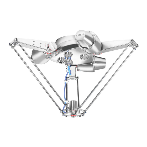
KR 3 D1200-2 HM Product description Overview of the robot system Overview The robot system of KR 3 D1200-2 HM comprises the following compo- nents: • Manipulator • Robot controller • smartPAD-2 • Connecting cables • Software • Options, accessories Fig. - Page 12 KR 3 D1200-2 HM Fig. 2-2: Main components of the manipulator Electrical installations Forearm Base frame Movable plate Upper arm Mounting flange Base frame The base frame is the base of the manipulator and houses the motor from A1 to A3.
- Page 13 KR 3 D1200-2 HM The spring assembly is designed to fix the 2 forearms with the upper arms. Fig. 2-4: Upper arm Base frame Upper arm Spring assembly Forearm Forearm Each upper arm is equipped with 2 forearms. The upper arms and the forearms are driven by the gear unit A1, A2 and A3 to move the movable plate.
-
Page 14: Intended Use
KR 3 D1200-2 HM Movable plate The mounting flange is installed on the movable plate and performs the rotational motion of axis 4. Fig. 2-7: Movable plate Motor and gearbox A4 Movable plate Connecting cable A4 Mounting flange Electrical installations The electrical installations comprise the following elements: •... - Page 15 Risk of personal injuries and property damage due to structure change of the manipulator If you change the structure of the manipulator, for example, by drilling holes without the permission of KUKA, personal injuries and property damage can occur. This can cause loss of guarantee and liability entitle- ments.
- Page 16 KR 3 D1200-2 HM 16/105 | www.kuka.com MA_KR_3_D1200-2_HM_V4 | Issued: 20.11.2023...
-
Page 17: Safety
• This “Safety” chapter refers to a mechanical component of an indus- trial robot. • If the mechanical component is used together with a KUKA robot controller, the “Safety” chapter of the operating instructions or as- sembly instructions of the robot controller must be used! This contains all the information provided in this “Safety”... -
Page 18: Ec Declaration Of Conformity And Declaration Of Incorporation
KR 3 D1200-2 HM 3.1.2 EC declaration of conformity and declaration of incorporation The industrial robot constitutes partly completed machinery as defined by the EC Machinery Directive. The industrial robot may only be put into op- eration if the following preconditions are met: •... - Page 19 • KUKA smartPAD • KUKA smartPAD-2 • KUKA smartPAD pro For robot controllers of the KR C5 series with KUKA System Soft- ware or VW System Software, only the model KUKA smartPAD-2 is used. For robot controllers of the KR C5 series with KUKA iiQKA.OS, on- ly the model KUKA smartPAD pro is used.
-
Page 20: Personnel
For KUKA iiQKA.OS: not relevant at present For KUKA System Software / VW System Software: Axis of motion that does not belong to the manipulator, yet is con- trolled with the robot controller. For example, KUKA linear unit, turn- tilt table and positioner Personnel... -
Page 21: Workspace, Safety Zone And Danger Zone
KR 3 D1200-2 HM • Connecting the industrial robot • Performing the risk assessment • Implementing the required safety functions and safeguards • Issuing the EC declaration of conformity • Affixing the CE mark • Creating the operating instructions for the system... -
Page 22: Mechanical Axis Limitation (Optional)
• Put manipulator out of operation. • Put external axis out of operation. • KUKA must be consulted before they are put back into operation. 3.4.2 Mechanical axis limitation (optional) Some manipulators can be fitted with adjustable mechanical axis limitation systems in axes A1 to A3. -
Page 23: Labeling On The Industrial Robot
KR 3 D1200-2 HM 3.4.4 Labeling on the industrial robot All plates, labels, symbols and marks constitute safety-relevant parts of the industrial robot. They must not be modified or removed. Labeling on the industrial robot consists of: • Identification plates •... - Page 24 The enabling switches on the smartPAD must be subjected to a function test at least once every 12 months and in certain specific cases. Information about function testing for KUKA robot controllers can be found in the “Safety” chapter of the operating or assembly instructions of the robot controller.
-
Page 25: Transportation
External axis (optional) The prescribed transport position of the external axis (e.g. KUKA linear unit, turn-tilt table, positioner) must be observed. Transportation must be carried out in accordance with the operating instructions or assembly in- structions of the external axis. - Page 26 • Only connect the manipulator to the corresponding robot controller. Do not impair safety functions Additional components (e.g. cables and hoses) not supplied by KUKA may be integrated into the industrial robot. If the safety functions are not taken into consideration, this may result in death, severe injuries or damage to property.
-
Page 27: Manual Mode
KR 3 D1200-2 HM • The ground conductor and the equipotential bonding cable are suffi- ciently rated and correctly connected. • The connecting cables are correctly connected and the connectors are locked. 3.5.4 Manual mode General Manual mode is the mode for setup work. Setup work is all the tasks that have to be carried out on the industrial robot to enable automatic opera- tion. -
Page 28: Automatic Mode
KR 3 D1200-2 HM Setup work in T2 If it is necessary to carry out setup work from inside the safeguarded area, the following must be taken into consideration in the operating mode Manual High Velocity (T2): • This mode may only be used if the application requires a test at a ve- locity higher than that possible in T1 mode. - Page 29 KR 3 D1200-2 HM DANGER Danger to life and limb due to live parts The robot system must be disconnected from the mains power supply prior to work on live parts. It is not sufficient to trigger an EMERGENCY STOP or safety stop, because parts remain live. Death or severe inju- ries may result.
-
Page 30: Decommissioning, Storage And Disposal
Use current safety data sheets Knowledge of the safety data sheets of the substances and mixtures used is a prerequisite for the safe use of KUKA products. Death, injuries or damage to property may otherwise result. • Request up-to-date safety data sheets from the manufacturers of hazardous substances regularly. -
Page 31: Technical Data
KR 3 D1200-2 HM Technical data Basic data, KR 3 D1200-2 HM Basic data KR 3 D1200-2 HM Number of axes Number of controlled axes Volume of working envelope Pose repeatability (ISO 9283) ± 0.05 mm Weight approx. 95 kg... -
Page 32: Axis Data, Kr 3 D1200-2 Hm
4, 7, 15, 25 m For detailed specifications of the connecting cables, see (>>> 7.2 "De- scription of the connecting cables" Page 70). Axis data, KR 3 D1200-2 HM Axis data Motion range -109 ° / 42 ° -109 ° / 42 °... - Page 33 Mastering position A3 0 ° Mastering position A4 0 ° Working envelope The following diagrams show the shape and size of the working envelope. Fig. 4-2: KR 3 D1200-2 HM, working envelope, side view MA_KR_3_D1200-2_HM_V4 | Issued: 20.11.2023 www.kuka.com | 33/105...
-
Page 34: Payloads, Kr 3 D1200-2 Hm
KR 3 D1200-2 HM Fig. 4-3: KR 3 D1200-2 HM, working envelope, top view Payloads, KR 3 D1200-2 HM Payloads Rated payload 3 kg Maximum paylaod 6 kg Rated supplementary load, upper 0 kg Maximum supplementary load, up- 0 kg... - Page 35 • A characteristic feature of the main axis system is that, among other things, the maximum possible inertia occurs about one of the 3 coordi- nate axes. Further information is contained in the KUKA Load documentation. MA_KR_3_D1200-2_HM_V4 | Issued: 20.11.2023 www.kuka.com | 35/105...
- Page 36 For start-up of the robot, additional input data are required in ac- cordance with the documentation for the system software. The mass inertia must be verified using KUKA Load. It is imperative for the load data to be entered in the robot controller! Fig.
- Page 37 KR 3 D1200-2 HM Fig. 4-6: Mounting flange D = 31.5 Flange loads Due to the motion of the payload (e.g. tool) mounted on the robot, forces and torques act on the mounting flange. These forces and torques depend on the motion profile as well as the mass, load center of gravity and mass moment of inertia of the payload.
-
Page 38: Foundation Loads, Kr 3 D1200-2 Hm
24 Nm Axial force F(a), radial force F(r), tilting torque M(k), torque about mount- ing flange M(g) Foundation loads, KR 3 D1200-2 HM Foundation loads The specified forces and moments already include the payload and the in- ertia force (weight) of the manipulator. -
Page 39: Plates And Labels
KR 3 D1200-2 HM Fig. 4-8: Foundation loads WARNING Normal loads and maximum loads for the foundations are specified in the table. The maximum loads must be referred to when dimensioning the founda- tions and must be adhered to for safety reasons. Failure to observe this can result in personal injury and damage to property. -
Page 40: Reach Duty To Communicate Information Acc. To Art. 33
KR 3 D1200-2 HM Item Description Identification plate Content is according to Machinery Directive. The specific content and data can be seen in the real object. REACH duty to communicate information acc. to Art. 33 As of June 2007, the Regulation (EC) 1907/2006 of the European Parlia- ment and of the Council dated 18 December 2006 on the registration, evaluation and authorization of chemicals (REACH Regulation) is in force. -
Page 41: Stopping Distances And Stopping Times
KR 3 D1200-2 HM • The wear on the brakes varies depending on the operating mode, ro- bot application and the number of STOP 0 stops triggered. You are recommended to check the stopping distance at least once a year. -
Page 42: Stopping Distances And Stopping Times For Stop 1
KR 3 D1200-2 HM 4.7.2.2 Stopping distances and stopping times for STOP 1 Fig. 4-10: Stopping distances for STOP 1 42/105 | www.kuka.com MA_KR_3_D1200-2_HM_V4 | Issued: 20.11.2023... - Page 43 KR 3 D1200-2 HM Fig. 4-11: Stopping times for STOP 1 MA_KR_3_D1200-2_HM_V4 | Issued: 20.11.2023 www.kuka.com | 43/105...
- Page 44 KR 3 D1200-2 HM 44/105 | www.kuka.com MA_KR_3_D1200-2_HM_V4 | Issued: 20.11.2023...
-
Page 45: Planning
• External forces (process forces) acting on the robot If one or more of these conditions are to apply during operation of the kin- ematic system, KUKA Service must be consulted. If the robot reaches its corresponding operation limit or if it is operated near the limit for a period of time, the built-in monitoring functions come into effect and the robot is automatically switched off. - Page 46 KR 3 D1200-2 HM Fig. 5-1: Installation illustration, cross-section Machine frame (user-made) Mounting base (option) Welding block Manipulator Hexagonal plate (user-made) M8×30-8.8 hexagon bolt (12x) M16×40-8.8 hexagon bolt (9x) 8 M12×40-8.8 hexagon bolt (12x) The specified dimension of the machine frame must be observed to make sure that the anchor forces can be safely transmitted to the foundation.
- Page 47 KR 3 D1200-2 HM Fig. 5-2: Machine frame installation Notice: The robot is delivered with upper arms at 45°by default.In order to avoid interference between upper arm and the mounting plates, the minimum distance from the upper arm to the center point of the robot is 300mm must be considered when designing the mounting plates.Otherwise the...
- Page 48 KR 3 D1200-2 HM Fig. 5-3: The minimum distance for anti-interference Procurement of mounting base (option, can be ordered as an option) The mounting base (option) could be acquired by manufacturing based on the dimensioned drawings (>>> Fig. 5-5). Stainless steel is recommended.
- Page 49 KR 3 D1200-2 HM Fig. 5-4: Mounting base M12×40-8.8 hexagon bolt (12x) M8×30-8.8 hexagon bolt (12x) Locating pin (3x) Mounting base (option) Base frame MA_KR_3_D1200-2_HM_V4 | Issued: 20.11.2023 www.kuka.com | 49/105...
- Page 50 KR 3 D1200-2 HM Fig. 5-5: Mounting base, dimensioned drawings Acquirement of hexagonal plate (user-made) Users can self-make the hexagonal plate based on the dimensioned draw- ings (>>> Fig. 5-6) (>>> Fig. 5-7). Stainless steel is recommended. 50/105 | www.kuka.com...
- Page 51 KR 3 D1200-2 HM Fig. 5-6: Hexagonal plate (user-made), dimensions MA_KR_3_D1200-2_HM_V4 | Issued: 20.11.2023 www.kuka.com | 51/105...
- Page 52 KR 3 D1200-2 HM Fig. 5-7: Hexagonal plate, cross-section Dimensioned assembly drawing The following drawing indicates the dimensions and the required founda- tion data of the mounting base after assembly. 52/105 | www.kuka.com MA_KR_3_D1200-2_HM_V4 | Issued: 20.11.2023...
- Page 53 KR 3 D1200-2 HM Fig. 5-8: Mounting base, dimensioned assembly drawing The following drawing indicates the bolt positions of the mounting base and the bolt positions of the machine frame. Fig. 5-9: Mounting bolts, overview M12×40-8.8 hexagon bolt (12x) M16×40-8.8 hexagon bolt (9x) M8×30-8.8 hexagon bolt (12x)
-
Page 54: Mounting Position Of Cable Clips
KR 3 D1200-2 HM Fig. 5-10: The robot and conveyor line, side view Conveyor line Fig. 5-11: Angle between the robot and conveyor lines, top view Conveyor lines Mounting position of cable clips The cable clips of the upper arm and the forearm are designed for fixing the connecting cable A4 with the manipulator during operation. -
Page 55: Connecting Cables And Interfaces
KR 3 D1200-2 HM Fig. 5-12: Mounting dimensions, cable clips Connecting cables and interfaces Connecting cables The connecting cables comprises all the cables that transfer energy and signals between the manipulator and the robot controller. The connecting cables are pre-installed on the rear cable set of the ma- nipulator. - Page 56 KR 3 D1200-2 HM • Route the motor cables and the data cables separately in metal ducts. If necessary, take additional measures to ensure electromagnetic com- patibility (EMC). Interface plate Interface plate is located at the rear of the base frame.
-
Page 57: Transportation
KR 3 D1200-2 HM Transportation Overview of transportation Transport position The manipulator must be transformed into the transport position before transportation. The following table specifies the axis angles when the manipulator is in the transport position: Axis Angle +45º +45º... -
Page 58: Transporting The Manipulator
KR 3 D1200-2 HM Package dimensions Fig. 6-3: Package dimensions Cartons Upper cardboard Manipulator Lower cardboard Tray Transporting the manipulator Description The manipulator must be transported with the lifting tackle according to the following instructions. Equipment The following equipment is required:... -
Page 59: Transporting The Manipulator With Fork Lift Trucks
KR 3 D1200-2 HM Precondition • The connecting cables are tied with a cable strap. • Any tools or equipment that impede the work must be removed from the system. Work safety WARNING Risk of personal injuries and property damage due to unsuitable... -
Page 60: Transporting The Manipulator With Lifting Tackle
KR 3 D1200-2 HM Fig. 6-5: Transportation by fork lift truck 3. Unpack the manipulator and remove the package. 6.2.2 Transporting the manipulator with lifting tackle Procedure 1. Insert 3 M10 rings into the mounting base. 2. Connect the ropes with the rings and the lifting tackle in the specified manner (>>>... - Page 61 KR 3 D1200-2 HM • Remove any used tools and equipment. • Check and make sure that the manipulator can be safely transported to the installation site. MA_KR_3_D1200-2_HM_V4 | Issued: 20.11.2023 www.kuka.com | 61/105...
- Page 62 KR 3 D1200-2 HM 62/105 | www.kuka.com MA_KR_3_D1200-2_HM_V4 | Issued: 20.11.2023...
-
Page 63: Start-Up And Recommissioning
KR 3 D1200-2 HM Start-up and recommissioning Starting up the ceiling-mounted manipulator Description The mounting base (option) is used for the installation of ceiling-mounted manipulator. The manipulator is fastened to the ceiling of the machine frame using the lifting tackle. -
Page 64: Installing The Mounting Base (Option) With The Manipulator
KR 3 D1200-2 HM • The connecting cables and ground conductors are routed and instal- led. • The machine frame must be ready for the start-up of the manipulator. Work safety CAUTION Risk of personal injuries and property damage due to unintentional... -
Page 65: Installing The Manipulator
KR 3 D1200-2 HM Fig. 7-1: Installing the mounting base M8×30-8.8 hexagon bolt (12x) Mounting base, option Sealing, option Locating pin, cylindrical (3x) Base frame 7.1.2 Installing the manipulator Procedure 1. Clean the bottom surface of the hexagonal plate(user-made). 2. Insert the 3 rings into the mounting base. -
Page 66: Connecting The Cables
KR 3 D1200-2 HM Fig. 7-2: Installing the manipulator Locating pin, cylindrical (3x) Mounting surface M12×40-8.8 hexagon bolt (12x) 7.1.3 Connecting the cables Procedure 1. Fasten the 2 ground conductors at the rear of the base frame. 2. Connect the data cable X31. -
Page 67: Installing The Forearms
KR 3 D1200-2 HM Fig. 7-3: Base frame, bottom interface Vacuum system interface Connecting cable set, A4 Brake release button 2. Move the manipulator until the axis from 1 to 3 are horizontal. 7.1.5 Installing the forearms Procedure 1. Install the spring assembly on the casing. -
Page 68: Connecting The Cable A4
KR 3 D1200-2 HM Fig. 7-4: Forearm assembly Upper arm Ball, D20 Spring assembly Forearm 7.1.6 Connecting the cable A4 Procedure 1. Plug in the connecting cable set A4 and fasten it with an open-ended wrench. 2. Assemble the 6 M4×12 hexagon flange bolts. - Page 69 KR 3 D1200-2 HM Fig. 7-6: Mounting dimensions, cable clips 6. Fix cable set A4 with the cable clips on the upper arm and forearm. Make sure that the upper arm and forearm can move freely without damaging cable set A4.
-
Page 70: Concluding Work
• Start up the robot system according to the “Start-up and recommis- sioning” chapter in the operating instructions of the robot controller. • Operate the manipulator according to the “Start-up and recommission- ing” chapter in the operating and programming instructions of KUKA System Software (KSS). Description of the connecting cables... -
Page 71: Description Of The Motor Cable
KR 3 D1200-2 HM Fig. 7-9: Connecting cable, ground conductor (option) Ground conductor (can be Conical spring washer ordered as an option) Hexagon nut Robot Conical spring washer Setscrew, M4 2x plain washer Ground conductor connec- tion, M4 ring cable lug... -
Page 72: Description Of The Data Cable
KR 3 D1200-2 HM Fig. 7-11: Wiring diagram, motor cable, XD20.1/XD20.2 - X30 7.2.2 Description of the data cable Fig. 7-12: Connecting cable, data cable, XF21 - X31 Fig. 7-13: Wiring diagram, data cable, XF21 - X31 72/105 | www.kuka.com... -
Page 73: Moving The Manipulator Via The Brake Release Button
KR 3 D1200-2 HM Moving the manipulator via the brake release button Description The brake release button is located on the bottom of the base frame. You can press the button to move the manipulator manually. Precondition • The robot controller is completely powered on. - Page 74 KR 3 D1200-2 HM This option is only for use in exceptional circumstances and emergencies, e.g. for freeing people. Precondition • The robot controller is switched off and secured with a padlock to pre- vent unauthorized persons from switching it on.
-
Page 75: Maintenance
KUKA. Information about KUKA College and its training program can be found at college.kuka.com or can be obtained directly from our subsidiaries. In the case of support and repair services provided by KUKA, KUKA Serv- ice must be informed in advance about potential contamination or haz- ards. - Page 76 KR 3 D1200-2 HM Oil change Lubricate with grease gun Lubricate with brush Lubricate with spray grease Tighten screw/nut Check component, visual inspection Clean component Exchange battery Exchange component Check toothed belt tension Fig. 8-1: Maintenance diagram 76/105 | www.kuka.com...
-
Page 77: Exchanging The Casing
Carry out a visual inspection of the years at the cable set A4 for damage. latest In the case of damage, have the ca- ble set A4 exchanged by KUKA Serv- ice. Exchanging the casing Description The casings must be exchanged according to the following instructions. - Page 78 KR 3 D1200-2 HM Screws of strength class 10.9 and higher as well as screws with test cer- tification may only be tightened once with the rated tightening torque. When the screws are first slackened they must be replaced with new ones.
-
Page 79: Exchanging The Bearing
KR 3 D1200-2 HM Fig. 8-2: Exchanging the casing Casing Spring assembly 3. Check whether the casing is damaged and exchange the damaged casings. 4. Install the forearm assembly. (>>> 8.4.2 "Installing the forearms" Page Exchanging the bearing Description The bearings must be exchanged according to the following instructions. - Page 80 KR 3 D1200-2 HM Work safety CAUTION Risk of personal injuries and property damage due to simultaneous repairing If you remove the 3 forearms at the same time, the movable plate may drop and cause bruise and crushes. • Do not remove the forearms simultaneously.
-
Page 81: Exchanging The Forearm
KR 3 D1200-2 HM If necessary, the bearings can be applied with edible grease. You must ensure that the grease will not contaminate the product. 4. Install the forearm assembly. (>>> 8.4.2 "Installing the forearms" Page Exchanging the forearm Description The following instructions describe the exchange of the forearm. -
Page 82: Removing The Forearms
KR 3 D1200-2 HM CAUTION Risk of personal injuries and property damage due to unintentional robot motions Unintentional robot motions can cause personal injuries and damage to property. • Switch off the robot controller and secure it with a padlock to pre- vent unauthorized persons from switching it on. -
Page 83: Exchanging The Cable Set A4
KR 3 D1200-2 HM Fig. 8-5: Forearm assembly Upper arm Ball, D20 Spring assembly Forearm Exchanging the cable set A4 Description The following sections describe the procedure for exchanging the cable set A4. Scope of application Time needed to carry out the whole task:45min... -
Page 84: Disassemble The Cable Set A4 Steps
KR 3 D1200-2 HM Screws of strength class 10.9 and higher as well as screws with test cer- tification may only be tightened once with the rated tightening torque. When the screws are first slackened they must be replaced with new ones. - Page 85 KR 3 D1200-2 HM Fig. 8-6: Housing cover Housing cover 2. Cut 4 cable straps and unplug motor connectors, then unscrew 1 M3 Hexagon nut with washers to disconnect the ground conductor. 3. Unscrew the plug screw on A4 housing and remove the cable set A4.
-
Page 86: Install The Cable Set A4
KR 3 D1200-2 HM Fig. 8-8: Removing the plate on cover A4 Hexagon flange bolt M4x12 Cable set A4 Plate cover A4 8. Unscrew 2 M3 Hexagon nuts with washers to disconnect the ground conductors. Cut the cable straps, then unplug the cable connectors. -
Page 87: Concluding Work
KR 3 D1200-2 HM Fig. 8-10: Exchanging the cable clips M4×35 hexagon flange bolt Connecting cable A4 Cable clips Hygienic Usit-washer 5. Pass the cable set A4 through the side hole on A4 housing, then fas- ten the plug screw onto the A4 Housing, tightening torque: 20 Nm. -
Page 88: Cleaning The Manipulator
KR 3 D1200-2 HM Cleaning the manipulator Description The manipulator must be cleaned according to the following work instruc- tions. These instructions are only valid for the manipulator. More information about cleaning the system components, tools and the robot controller is contained in the respective manufacturer documenta- tion. -
Page 89: Concluding Work
KR 3 D1200-2 HM 4. Install any removed safety equipment and check whether it can work correctly. 5. Put back the removed enclosures. 8.6.2 Concluding work The following concluding work must be done: • Do function test to make sure that the robot system can operate func- tionally. - Page 90 KR 3 D1200-2 HM 90/105 | www.kuka.com MA_KR_3_D1200-2_HM_V4 | Issued: 20.11.2023...
-
Page 91: Repair
KUKA. Information about KUKA College and its training program can be found at college.kuka.com or can be obtained directly from our subsidiaries. In the case of support and repair services provided by KUKA, KUKA Serv- ice must be informed in advance about potential contamination or haz- ards. - Page 92 KR 3 D1200-2 HM 92/105 | www.kuka.com MA_KR_3_D1200-2_HM_V4 | Issued: 20.11.2023...
-
Page 93: Decommissioning, Storage And Disposal
KR 3 D1200-2 HM Decommissioning, storage and disposal 10.1 Decommissioning the manipulator Description This section describes all the work required for decommissioning the robot if the robot is to be removed from the system. After decommissioning, it is prepared for storage or transportation. -
Page 94: Unplugging The Connections
KR 3 D1200-2 HM Work safety CAUTION Risk of personal injuries and property damage due to unintentional robot motions Unintentional robot motions can cause personal injuries and damage to property. • Switch off the robot controller and secure it with a padlock to pre- vent unauthorized persons from switching it on. -
Page 95: Storage
KR 3 D1200-2 HM • Prepare the robot for storage if the robot is not to be reinstalled. 10.2 Storage Description The following regulations must be observed for putting the manipulator in- to long-term storage: • The storage place must be as dry and dust-free as possible. - Page 96 KR 3 D1200-2 HM Material Subassembly, component Additional information Copper Cables, wires Steel Gear units, screws, wash- Electrical parts Electronic components, Dispose of as electrical such as RDC, EDS scrap without disassem- bling. Motors Dispose of motors without dismantling. Plastics...
-
Page 97: Appendix
KR 3 D1200-2 HM Appendix 11.1 Tightening torques Tightening torques The following tightening torques (Nm) are valid for screws and nuts where no other specifications are given. The specified values apply to lightly oiled black (e.g. phosphated) and coated (e.g. mech. galv., zinc flake plating, screw locking elements) screws and nuts. -
Page 98: Auxiliary And Operating Materials Used
KR 3 D1200-2 HM 11.2 Auxiliary and operating materials used Product designation / Manufacturer designation / Article number Address Drei Bond type 1305 Adhesive and sealant Drei Bond GmbH Carl-Zeiss-Ring 13 0000-184-175 D-85737 Ismaning Germany LOCTITE 510 Adhesive and sealant Henkel Asia Pacific &... - Page 99 KR 3 D1200-2 HM EN ISO 10218-1:2011 Robots and robotic devices – Safety requirements for industri- al robots: Part 1: Robots Note: Content equivalent to ANSI/RIA R15.06-2012, Part 1 EN ISO 14159:2008 Safety of machinery Hygiene requirements for the design of machinery...
- Page 100 KR 3 D1200-2 HM 100/105 | www.kuka.com MA_KR_3_D1200-2_HM_V4 | Issued: 20.11.2023...
-
Page 101: Kuka Service
‒ System software diagnosis package Additionally for KUKA Sunrise: Existing projects including applica- tions For versions of KUKA System Software older than V8: Archive of the software (Diagnosis package is not yet available here.) ‒ Application used ‒ External axes used 12.2... - Page 102 KR 3 D1200-2 HM 102/105 | www.kuka.com MA_KR_3_D1200-2_HM_V4 | Issued: 20.11.2023...
-
Page 103: Index
Arctic..............8 EN ISO 12100:2010........98 Automatic mode..........28 EN ISO 14159:2008........99 Auxiliary materials used......... 98 EX..............8 Axis data, KR 3 D1200-2 HM......32 External axes..........17 Axis limitation, mechanical......22 External axis..........10, 20 Axis range..........8, 18 F................8 Basic data, KR 3 D1200-2 HM......31 F exclusive............8... - Page 104 Stopping time..........40 P................9 Stopping times..........40 PA..............9 Storage..........30, 93, 95 Payload diagram..........36 Support request..........101 Payloads, KR 3 D1200-2 HM......34 System integrator........18–20 Personal protective equipment...... 20 Personnel............20 Phi..............9 Planning............45 T1 (operating mode)........ 10, 19 Plant integrator..........19 T2 (operating mode)........
- Page 105 KR 3 D1200-2 HM Technical data..........31 Terms used............8 Terms, safety..........18 Tightening torques.......... 97 Training..........7, 75, 91 Transportation.......... 25, 57 Transportation, fork lift truck......59 Transportation, lifting tackle......60 Transporting the manipulator......58 Turn-tilt table...........17 UL 1740:2018..........99 Unplugging the connections......94...
Need help?
Do you have a question about the KR 3 D1200-2 HM and is the answer not in the manual?
Questions and answers