Kyocera PF-100 Service Manual
Hide thumbs
Also See for PF-100:
- Service manual (126 pages) ,
- Service manual (124 pages) ,
- Service manual (168 pages)
Table of Contents
Advertisement
Advertisement
Table of Contents

Subscribe to Our Youtube Channel
Related Manuals for Kyocera PF-100


Summary of Contents for Kyocera PF-100
- Page 1 PF-100/120 SERVICE MANUAL Published in August 2011 843LF112 3LFSM062 Rev.2...
- Page 2 CAUTION RISK OF EXPLOSION IF BATTERY IS REPLACED BY AN INCORRECT TYPE. DISPOSE OF USED BATTERIES ACCORDING TO THE INSTRUCTIONS. It may be illegal to dispose of this battery into the municipal waste stream. Check with your local solid waste officials for details in your area for proper disposal. ATTENTION IL Y A UN RISQUE D’EXPLOSION SI LA BATTERIE EST REMPLACEE PAR UN MODELE DE TYPE INCORRECT.
- Page 3 Revision history Revision Date Replaced pages Remarks 13 March 2008 1-2-1, 1-2-2 4 August 2011 Add PF-120, Safety precautions, Address...
- Page 4 This page is intentionally left blank.
-
Page 5: Safety Precautions
Safety precautions This booklet provides safety warnings and precautions for our service personnel to ensure the safety of their customers, their machines as well as themselves during maintenance activities. Service personnel are advised to read this booklet carefully to familiarize themselves with the warnings and precautions described here before engaging in maintenance activities. - Page 6 Safety warnings and precautions Various symbols are used to protect our service personnel and customers from physical danger and to prevent damage to their property. These symbols are described below: DANGER: High risk of serious bodily injury or death may result from insufficient attention to or incorrect compliance with warning messages using this symbol.
- Page 7 1.Installation Precautions WARNING • Do not use a power supply with a voltage other than that specified. Avoid multiple connections to one outlet: they may cause fire or electric shock. When using an extension cable, always check that it is adequate for the rated current....................•...
-
Page 8: Specifications 1
2.Precautions for Maintenance WARNING • Always remove the power plug from the wall outlet before starting machine disassembly....• Always follow the procedures for maintenance described in the service manual and other related brochures............................• Under no circumstances attempt to bypass or disable safety features including safety mechanisms and protective circuits. - Page 9 • Do not remove the ozone filter, if any, from the copier except for routine replacement..... • Do not pull on the AC power cord or connector wires on high-voltage components when removing them; always hold the plug itself...................... •...
- Page 10 This page is intentionally left blank.
-
Page 11: Table Of Contents
3LF/3N2 CONTENTS 1-1 Specifications 1-1-1 Specifications............................1-1-1 1-1-2 Parts names............................1-1-2 1-1-3 Machine cross section ..........................1-1-3 1-2 Installation 1-2-1 Installation environment ..........................1-2-1 1-2-2 Unpacking ...............................1-2-2 (1) Unpacking ............................1-2-2 (2) Removing the cassette spacer ......................1-2-3 1-3 Troubleshooting 1-3-1 Paper misfeed detection .........................1-3-1 (1) Paper misfeed indication ........................1-3-1 (2) Paper misfeed detection........................1-3-2 1-3-2 Self-diagnostic function...........................1-3-3 (1) Self-diagnostic function ........................1-3-3... - Page 12 3LF/3N2 This page is intentionally left blank.
-
Page 13: Specifications
3LF/3N2 1-1 Specifications 1-1-1 Specifications Paper size........A4, A5, B5, Letter, Legal, Folio, Oficio II Paper capacity ........ 250 sheets (80 g/m Dimensions ........375 mm (W) × 390 mm (D) × 100 mm (H) " (W) × 15 " (D) × 3 "... -
Page 14: Parts Names
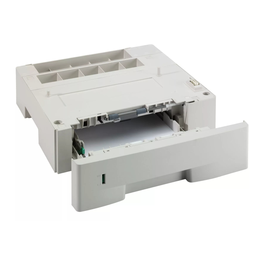
3LF/3N2 1-1-2 Parts names Figure 1-1-1 Cassette Paper gauge Interface connector Positioning pins 1-1-2... -
Page 15: Machine Cross Section
3LF/3N2 1-1-3 Machine cross section Paper path Figure 1-1-2 1-1-3... - Page 16 3LF/3N2 This page is intentionally left blank. 1-1-4...
-
Page 17: Installation Environment
3LF/3N2-1 1-2 Installation 1-2-1 Installation environment Installation location (Must comply with the same environment as the main unit installation.) Avoid direct sunlight or bright lighting. Ensure that the photo-conductor will not be exposed to direct sunlight or other strong light when removing paper jams. Avoid locations subject to high temperature and high humidity or low temperature and low humidity;... -
Page 18: Unpacking
3LF/3N2-1 1-2-2 Unpacking (1) Unpacking Figure 1-2-1 Paper feeder Outer case Top pad Plastic sheet Installation Guide Front /rear pad assembly Caution: Place the machine on a level surface. See the Installation Guide for installation. 1-2-2... -
Page 19: Removing The Cassette Spacer
3LF/3N2 (2) Removing the cassette spacer Procedure 1. Pull the cassette out. 2. Remove the cassette spacer. 3. Push the cassette back in. Cassette spacer Cassette Figure 1-2-2 1-2-3... - Page 20 3LF/3N2 This page is intentionally left blank. 1-2-4...
-
Page 21: Paper Misfeed Detection
3LF/3N2 1-3 Troubleshooting 1-3-1 Paper misfeed detection (1) Paper misfeed indication If paper jams in the paper feeder, the printer automatically goes offline, and the Jam indicator will flash rapidly. Status Mon- itor or COMMAND CENTER can indicate the location of the paper jam (the component where the paper jam has occurred). -
Page 22: Paper Misfeed Detection
3LF/3N2 (2) Paper misfeed detection Printer Paper feeder 1 Paper feeder 2 PF paper sensor PF paper feed sensor Figure 1-3-2 1-3-2... -
Page 23: Self-Diagnostic Function
3LF/3N2 1-3-2 Self-diagnostic function (1) Self-diagnostic function The printer is equipped with self-diagnostic function which automatically halts the printer when an error is detected. The four indicators (Jam, Paper, Attention, Toner) are simultaneously lit, then indicate a specific error by the combination of the four indicators. - Page 24 3LF/3N2 Sequence of display Indicates the occurrence of a self diagnostics error. 1.6 s 1.6 s 0.8 s 0.8 s Example of self-diagnostic code: 2610 (Refer to the following code conversion table) 0.8 s 0.8 s 0.8 s Indication example Lit (Green) 0.8 s Off (Amber)
-
Page 25: Self Diagnostic Codes
3LF/3N2 (3) Self diagnostic codes Remarks Code Contents Causes Check procedures/corrective measures 0420 Paper feeder communication error Improper installation Follow installation instruction carefully Communication error between paper feeder. again. printer’s control PWB and paper Defective harness Reinsert the connector. Also check for con- feeder. -
Page 26: Electric Problems
3LF/3N2 1-3-3 Electric problems Problem Causes Check procedures/corrective measures Actuators of PF paper feed Repair or replace. Defective paper jam sensor does not operate detecting. smoothly. A piece of paper torn from a Check visually and remove it, if any. sheet is caught around actuator of PF paper feed sensor. -
Page 27: Mechanical Problems
3LF/3N2 1-3-4 Mechanical problems Problem Causes/check procedures Corrective measures Check if the surfaces of the following rollers Clean with isopropyl alcohol. No primary paper feed. are dirty with paper powder: pickup roller and paper feed roller. Check if the pickup roller and paper feed roller Check visually and replace any deformed are deformed. - Page 28 3LF/3N2 This page is intentionally left blank. 1-3-8...
-
Page 29: Assembly And Disassembly
3LF/3N2 1-4 Assembly and Disassembly 1-4-1 Precautions for assembly and disassembly (1) Precautions Be sure to turn the power switch of the machine off and disconnect the power plug before starting disassembly of the paper feeder. When handling PWBs, do not touch connectors with bare hands or damage the PWB. Do not touch any PWB containing ICs with bare hands or any object prone to static charge. -
Page 30: Paper Feed Section
3LF/3N2 1-4-2 Paper feed section (1) Detaching and refitting the middle roller/feed bracket assembly (paper feed roller and pickup roller) Procedure 1. Remove the cassette from the paper feeder. Paper feeder Cassette Figure 1-4-1 2. Remove the middle roller assembly from the middle C shaft and holders. - Page 31 3LF/3N2 4. While pressing the latch and slide the release holder. 5. Push the lock lever and then remove the Release holder feed bracket assembly. 6. Check or replace the feed bracket assembly (paper feed roller and pickup roller) and refit all the removed parts.
-
Page 32: Detaching And Refitting The Retard Roller Assembly (Retard Roller)
3LF/3N2 (2) Detaching and refitting the retard roller assembly (retard roller) Procedure 1. Remove the cassette from the paper feeder. 2. Push the cassette holder down until it locks. Paper feeder Cassette holder Cassette Figure 1-4-4 3. Unhook two hooks and then remove the Retard guide retard guide. - Page 33 3LF/3N2 4. Remove the retard roller assembly from the projections. Retard roller assembly Projections Projections Retard roller assembly Figure 1-4-6 5. Check or replace the retard roller assembly (retard roller) and refit all the removed parts. Retard roller Caution: Before refitting the retard roller assembly assembly, firmly install the spring onto the projection of the retard roller assembly.
-
Page 34: Pwb
3LF/3N2 1-4-3 (1) Detaching and refitting the PF main PWB Procedure 1. Remove the paper feeder from the printer. 2. Remove two screws and then remove the Top cover Screw top cover. Screw Figure 1-4-8 3. Remove two screws. Ground wire 4. -
Page 35: Paper Feed Section
3LF/3N2 2-1 Mechanical Construction 2-1-1 Paper feed section (1) Paper feed section The paper feeder conveys paper from the cassette to the printer. Cassette can hold up to 250 sheets of paper. Paper is fed from the paper feeder by the rotation of the pickup roller and paper feed roller. The retard roller prevents multiple sheets from being fed at one time, via the torque limiter. - Page 36 3LF/3N2 Printer Power Control PWB source PWB Paper feeder +3.3 V PFSEL UART interface connector +24 V Paper feeder 1 PF main PWB PF paper feed sensor PF cassette switch Cassette open/close detection circuit PF paper feed motor PF paper PF paper sensor feed clutch...
-
Page 37: Electrical Parts Layout
3LF/3N2 2-2 Electrical Parts Layout 2-2-1 Electrical parts layout (1) Electrical parts layout Machine left Machine inside Machine right Figure 2-2-1 Electrical parts layout PF main PWB ..........Controls electrical components in the paper feeder and serial communi- cations with the printer. PF paper sensor .......... - Page 38 3LF/3N2 This page is intentionally left blank. 2-2-2...
-
Page 39: Pf Main Pwb
3LF/3N2 2-3 Operation of the PWBs 2-3-1 PF main PWB Paper feeder 1 PF main PWB +3.3 V +24 V PFSI Control PWB (Printer) PFSO PFSEL +3.3 V +24 V PF main PWB (paper feeder 2) +3.3 V +3.3 V CASESN PF cassette PFEED... - Page 40 3LF/3N2 Figure 2-3-2 PF main PWB silk-screen diagram Connector Signal Voltage Description +24V3 24 V DC 24 V DC power source Connected FEEDCLN 0/24 V DC PF paper feed clutch: On/Off to the PF +24V3 24 V DC 24 V DC power source paper feed TRANSCLN 0/24 V DC...
-
Page 41: Appendixes
3LF/3N2 2-4 Appendixes 2-4-1 Appendixes (1) Wiring diagram 2-4-1... - Page 42 3LF/3N2 This page is intentionally left blank. 2-4-2...
- Page 43 2011...
- Page 44 2011...
Need help?
Do you have a question about the PF-100 and is the answer not in the manual?
Questions and answers