Advertisement
Quick Links
Advertisement

Subscribe to Our Youtube Channel
Related Manuals for Rohm BM2P141X


Summary of Contents for Rohm BM2P141X
- Page 1 AC/DC Converter Non-Isolation Buck Converter PWM method 10 W 14 V BM2P141X Reference Board...
- Page 2 [8] Be sure to wear insulated gloves when handling is required during operation. After Use [9] The ROHM Evaluation Board contains the circuits which store the high voltage. Since it stores the charges even after the connected power circuits are cut, please discharge the electricity after using it, and please deal with it after confirming such electric discharge.
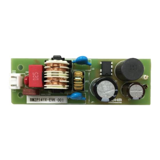
- Page 3 BM2P141X-EVK-001 The BM2P141X-EVK-001 evaluation board outputs 14 V voltage from the input of 90 Vac to 264 Vac. The output current supplies up to 0.715 A. The BM2P141X which is PWM method DC/DC converter IC built-in 650 V MOSFET is used.
- Page 4 Maximum Output Power Po of this reference board is 10.0 W. The derating curve is shown on the right. If ambient temperature is over 40°C, Please adjust load continuous time by over 105 °C of any parts surface temperature. Ambient Temparature Ta [℃] Figure 3. Temperature Deleting curve © 2019 ROHM Co., Ltd. No. 61UG024E Rev.002 2/20 Jul. 2021...
- Page 5 AC90-264V Figure 4. BM2P141X-EVK-001 Application Circuit The BM2P141X is non-insulation method without opto-coupler and feeds back the VCC voltage to 14.0 V typ. This VCC voltage is the voltage between the VCC pin and the GND_IC pin. The output voltage VOUT is defined by the following equation.
- Page 6 Soft Start function Dimension W(Typ) x D(Typ) x H(Max) DIP7K 9.20 mm x 6.35 mm x 4.30 mm Pitch 2.54 mm Figure 6. Block Diagram Figure 7. DIP7K Package Table 1. BM2P141X PIN description ESD Diode Name Function ✔ GND_IC ✔ ✔...
- Page 7 ( ������ ) ���� Calculate L value to operate in discontinuous mode. ( ������ ) −���� �� L < ton ( ������ ) × �� = 206.3 [μH] �� �� © 2019 ROHM Co., Ltd. No. 61UG024E Rev.002 5/20 Jul. 2021...
- Page 8 + �� + �� ���� ������ �� ������ �� �������������� = × �� × ���� ( ������ ) × �� ( ������ ) ���� �� �� ���� �� �� © 2019 ROHM Co., Ltd. No. 61UG024E Rev.002 6/20 Jul. 2021...
- Page 9 (Max): 380 V. Consider the derating and select 600 V diode. Because the current flowing to the IC is small enough, we use the 0.2 A / 600 V RRE02VSM6S. © 2019 ROHM Co., Ltd. No. 61UG024E Rev.002 7/20 Jul. 2021...
- Page 10 × √ = 0.93 �� �� The ripple current of the capacitor, [ ������ ] = √ �� �� − �� = √0.93 − 0.715 = 0.59 �� �� ������ © 2019 ROHM Co., Ltd. No. 61UG024E Rev.002 8/20 Jul. 2021...
- Page 11 5.1 Discharge Resistor : R1,R2,R3 The resistor is for discharging X - Capacitor (C1). Considering withstand voltage, 3 pcs of chip resistance of ROHM product MCR18 (200 V withstand voltage) are connected in series. 220 kΩ is used in 3 pcs in series so that it becomes 45 V or less after 1 second after turning off the power supply.
- Page 12 = 90 Vac =115 Vac =230 Vac =264 Vac Output Current [mA] Output Current [mA] Figure 10. Load Regulation (I vs. P Figure 11. Load Regulation (I vs. P LOSS LOSS © 2019 ROHM Co., Ltd. No. 61UG024E Rev.002 10/20 Jul. 2021...
- Page 13 13.648 1200 16.378 3.679 81.66 20.65 13.641 1260 17.188 3.462 83.23 22.50 13.609 1330 18.100 4.398 80.45 0.09 0.000 1270 0.000 0.090 0.00 0.17 0.000 1340 0.000 0.172 0.00 © 2019 ROHM Co., Ltd. No. 61UG024E Rev.002 11/20 Jul. 2021...
- Page 14 13.607 1200 16.328 4.242 79.38 24.02 13.583 1390 18.880 5.140 78.60 23.95 13.520 1400 18.928 5.022 79.03 0.25 0.000 1400 0.000 0.250 0.00 0.30 0.000 1410 0.000 0.300 0.00 © 2019 ROHM Co., Ltd. No. 61UG024E Rev.002 12/20 Jul. 2021...
- Page 15 100 200 300 400 500 600 700 800 Output Current [mA] Output Current [mA] Figure 14. Switching Frequency (I vs. F Figure 15. Coil Peak Current (I vs. Ipeak) © 2019 ROHM Co., Ltd. No. 61UG024E Rev.002 13/20 Jul. 2021...
- Page 16 = 0.715 A MOSFET V Diode VAnode-Cathode Diode I MOSFET IDrain Figure 20. MOSFET V = 264 Vac, Output Short Figure 21. Diode V = 264 Vac, Output Short © 2019 ROHM Co., Ltd. No. 61UG024E Rev.002 14/20 Jul. 2021...
- Page 17 = 115 Vac, I = 10 mA → 0.715 A = 0.715 A → 10 mA Figure 26. V = 230 Vac, I Figure 27. V = 230 Vac, I © 2019 ROHM Co., Ltd. No. 61UG024E Rev.002 15/20 Jul. 2021...
- Page 18 Figure 31. V = 230 Vac, I = 0.5 A Figure 32. V = 115 Vac, I = 0.715 A Figure 33. V = 230 Vac, I = 0.715 A © 2019 ROHM Co., Ltd. No. 61UG024E Rev.002 16/20 Jul. 2021...
- Page 19 = 110 Vac / 60 Hz, I = 0.715 A Figure 37. V = 230 Vac / 50 Hz, I = 0.715 A QP margin = 6.6 dB QP margin = 6.0 dB © 2019 ROHM Co., Ltd. No. 61UG024E Rev.002 17/20 Jul. 2021...
- Page 20 BM2P141X-EVK-001 User’s Guide Schematics = 90~264 Vac, V = 14 V Figure 38. BM2P141X-EVK-001 Schematics Bill of Materials Table 11. BoM of BM2P141X-EVK-001 Part Configuration Qty. Type Value Description Part Number Manufacture Reference mm (inch) X2 Capacitor 0.22 275Vac, ±20%...
- Page 21 BM2P141X-EVK-001 User’s Guide Size : 91 mm x 30 mm Figure 39. Top Silkscreen (Top view) Figure 40. Bottom Layout (Top view) © 2019 ROHM Co., Ltd. No. 61UG024E Rev.002 19/20 Jul. 2021...
- Page 22 BM2P141X-EVK-001 User’s Guide Revision History Date Rev. Changes Jul.2019 New Release Jul.2021 ・P6 correct L formula and result © 2019 ROHM Co., Ltd. No. 61UG024E Rev.002 20/20 Jul. 2021...
- Page 23 Products. ROHM does not grant you, explicitly or implicitly, any license to use or exercise intellectual property or other rights held by ROHM or any other parties. ROHM shall have no responsibility whatsoever for any dispute arising out of the use of such technical information.
Need help?
Do you have a question about the BM2P141X and is the answer not in the manual?
Questions and answers