
Related Manuals for Motorola solutions RM Series


Summary of Contents for Motorola solutions RM Series
- Page 1 RM Series Two-Way Radio User Guide RMU2080d *68012009073* AUGUST 2024 68012009073-BD © 2024 Motorola Solutions, Inc. All Rights Reserved.
-
Page 2: Table Of Contents
68012009073-BD Contents Contents Intellectual Property and Regulatory Notices..............5 Safety and Compliance Information.................. 6 RF Energy Exposure and Product Safety Guide for Two-way Radios.............6 Notice to Users (FCC and Innovation, Science and Economic Development Canada (ISED))....6 FCC Licensing Information........................6 Batteries and Chargers Safety Information....................7 Operational Safety Guidelines...................... - Page 3 68012009073-BD Contents 4.6.2 Setting iVOX without Accessories..................24 4.6.3 Enabling Power Up Tone Mode..................24 4.6.4 Resetting to Factory Default....................25 4.6.5 Enabling Voice Prompt in User Mode................25 4.6.6 Setting the Keypad Sounds....................25 4.6.7 Locking or Unlocking the Keypad..................25 4.7 Accessing Menu..........................25 4.7.1 Setting Sensitivity Levels for VOX or iVOX................
- Page 4 7.2 UHF Default Frequencies Chart ......................46 7.3 Interference Eliminator Codes......................47 7.4 Digital Interference Eliminator Codes....................47 Chapter 8: Authorized Accessories List ................. 51 Chapter 9: Motorola Solutions Limited Warranty for the United States and Canada.. 52 9.1 Warranty............................52 9.2 Products and Accessories....................... 52 9.3 Exclusions............................52 9.4 Software............................53...
-
Page 5: Intellectual Property And Regulatory Notices
License Rights The purchase of Motorola Solutions products shall not be deemed to grant either directly or by implication, estoppel or otherwise, any license under the copyrights, patents or patent applications of Motorola Solutions, except for the normal nonexclusive, royalty-free license to use that arises by operation of law in the sale of a product. -
Page 6: Safety And Compliance Information
This device must accept any interference received, including interference that may cause undesired operation. ● Changes or modifications made to this device, not expressly approved by Motorola Solutions, could void the authority of the user to operate this equipment. FCC Licensing Information This device complies with Parts 90 and 15 of the Federal Communications Commission (FCC) Rules. -
Page 7: Batteries And Chargers Safety Information
2. Use of accessories not recommended by Motorola Solutions may result in fire, electric shock, or injury. 3. To reduce damage to the electric plug and cord, pull by plug rather than the cord when disconnecting the charger. -
Page 8: Chapter 1: Introduction
Introduction This user guide covers the operation of your radio. This user guide covers multiple RM Series models, and may detail some features your radio does not have. The radio model information is provided at the bottom of the radio. - Page 9 68012009073-BD Chapter 1: Introduction Table 2: Radio Cleaning Guideline □□□ Use a soft damp cloth to clean Do not use alcohol or cleaning Do not immerse in water. the exterior. solutions. Table 3: Guideline for Submerged Radio in Water Turn off your radio and remove Do not use your radio until com- Dry with soft cloth.
-
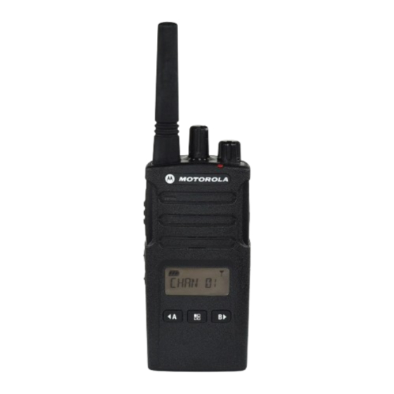
Page 10: Chapter 2: Radio Overview
Accessory Connector Allows you to connect compatible audio accessories to your radio. Battery All RM Series radios come with a Lithium-Ion (Li-Ion) battery. Model Label Indicates the model of your radio. Push-to-Talk (PTT) button Allows you to press and hold down this button to talk, and release it to listen. -
Page 11: Led Indicators
68012009073-BD Chapter 2: Radio Overview Label Item Description Channel Selector Knob Allows you to switch the radio to different channels. On/Off/Volume Control Knob Allows you to turn the radio on or off, and adjust the volume. LED Indicator Provides battery status, power-up status, radio call information, and scan status. - Page 12 68012009073-BD Chapter 2: Radio Overview Radio Status LED Indication Idle Programming Mode /Chan- Blinking green nel Mode Scan Mode Rapid blinking red Transmit (Tx)/Receive (Rx) Solid red Transmit in Low Power Select Solid orange VOX/iVOX Mode Double blinking red...
-
Page 13: Chapter 3: Getting Started
68012009073-BD Chapter 3: Getting Started Chapter 3 Getting Started This chapter describes the basic radio operations. Installing the Battery Your radio uses a rechargeable Lithium Ion (Li-Ion) battery. Procedure: 1. Turn off your radio. 2. Fit the battery tab into the slots at the bottom of the radio. 3. -
Page 14: Battery Specifications
25 % discharge, lasts even longer. Motorola Solutions batteries are designed specifically to be used with a Motorola Solutions charger and vice versa. Charging batteries with non-Motorola Solutions equipment may lead to battery damage and void the battery warranty. -
Page 15: Battery Life
Standard Power Supply ● Rapid Power Supply To charge the battery with the radio attached, place it in a Motorola Solutions-approved Drop-in Tray Single- Unit Charger (SUC) or Drop-in Tray Multi-Unit Charger (MUC). NOTE: Your radio comes with the standard power supply. - Page 16 68012009073-BD Chapter 3: Getting Started 5. To charge batteries, perform one of the following actions: Then Charging radio (battery installed) using the Insert the radio (with battery installed) into the charger. Charging a stand-alone battery using the SUC a. Insert the battery into the charger. (Inside surface of the battery facing the front of the charger).
-
Page 17: Charger Led Indication
68012009073-BD Chapter 3: Getting Started Then Charging batteries using Multi-Unit Charger Insert the radio or battery into the charging (MUC) pocket with the radio or battery facing away from the contacts. NOTE: The MUC allows drop-in charging of up to six radios or batteries. Batteries can be charged inside the ra- dios or removed and placed in the MUC separately. -
Page 18: Estimated Charging Time
68012009073-BD Chapter 3: Getting Started Indication Status Error NOTE: Re-position Fast blinking red the battery pack to fix the error. Standby NOTE: Battery tem- perature is too Slowly blinking amber warm or too cold or wrong power volt- age is used. Blink red one time Battery level is low Blink amber two times... -
Page 19: Turning The Radio On
68012009073-BD Chapter 3: Getting Started Turning the Radio On Procedure: To turn on the radio, rotate the On/Off/Volume knob clockwise. The radio plays one of the followings: ● The radio sounds a tone and announces the channel number. ● The radio announces the battery level and channel numbers. ●... -
Page 20: Home Screen Overview
68012009073-BD Chapter 3: Getting Started Home Screen Overview Item Number Icons Description Battery Level Provides the remaining battery level information. Scan Displays when the radio is set to SCAN mode. Internal Voice Operated Trans- Displays when iVOX/VOX is enabled, program- mission (iVOX) or Voice Operat- ming MIC, or MIC gain features. - Page 21 68012009073-BD Chapter 3: Getting Started Item Number Icons Description Channel Indicator Displays when programming channel features. NOTE: The channel and code radio display can be different for each radio depending on the pre-programmed radio defaults and features available in the particular model or region. The backlight turns on when pressing any button except the PTT button.
-
Page 22: Chapter 4: Basic Radio Operations
68012009073-BD Chapter 4: Basic Radio Operations Chapter 4 Basic Radio Operations This chapter explains the basic operations that you can perform on your radio. Selecting Channels Procedure: To select a channel, rotate the Channel Selector knob until you reach the required channel. You hear the selected channel voice prompt from your radio. -
Page 23: Signal Strength Indicator And Channel Busy Indicators
68012009073-BD Chapter 4: Basic Radio Operations 3. To listen, release the PTT button. Signal Strength Indicator and Channel Busy Indicators When there is an activity on a frequency, the Signal Strength indicator icon illuminates and the radio LED blinks. When your radio is in the receiving mode and there is activity on the same frequency and code as your radio, the Signal Strength indicator icon can change from 1 (weakest) to 6 (strongest) depending on the radio reception coverage. -
Page 24: Setting Vox With Compatible Vox Accessories
VOX can be temporarily disabled by pressing the PTT button or by removing the audio accessory. NOTE: To order accessories, refer to the followings: http://www.motorolasolutions.com/RMseries b. 1800-448-6686 c. Contact your Motorola Solutions point of purchase. 4.6.2 Setting iVOX without Accessories Procedure: To enable Internal Voice Operated Transmission (iVOX), press the PTT button while turning on the radio. -
Page 25: Resetting To Factory Default
68012009073-BD Chapter 4: Basic Radio Operations ● The radio sounds a tone and announces the channel number. ● The radio announces the battery level and channel numbers. ● The radio is silent. Audible tones are disabled. 4.6.4 Resetting to Factory Default This feature sets all radio features back to the default settings. -
Page 26: Setting Sensitivity Levels For Vox Or Ivox
68012009073-BD Chapter 4: Basic Radio Operations 3. Once you are at the desired option settings, perform one of the following actions: ● To save the configured settings, press the Menu button. ● To save and exit from the menu, press and hold the PTT button. ●... -
Page 27: Chapter 5: Programming Features
68012009073-BD Chapter 5: Programming Features Chapter 5 Programming Features This chapter describes the operations of the features available in your radio. Advanced Configuration Mode Advanced Configuration mode allows you to configure additional features through the radio front panel. You can customize the following features: ●... -
Page 28: Entering Advanced Configuration Mode
68012009073-BD Chapter 5: Programming Features ● To continue programming, press the PTT button. ● To save settings and enter the Idle Programming mode, press and hold the PTT button. ● To exit Idle Programming mode, press and hold the PTT button twice. ●... -
Page 29: Programming The Scramble Code
68012009073-BD Chapter 5: Programming Features 3. Perform one of the following actions: ● To save and exit the programming mode, press and hold the PTT button. ● To continue to the next programming feature without saving, press the PTT button. 5.1.4 Programming the Scramble Code The scramble feature makes your transmissions sound garbled to anyone listening without the same... -
Page 30: Programming The Call Tones
68012009073-BD Chapter 5: Programming Features 5.1.6 Programming the Call Tones Call Tones feature allows you to transmit an audible tone to other radios on the same channel to alert them that you are about to talk or to alert them without speaking. In the Call Tone Selection Mode, you can configure the type of call tone for your radio. -
Page 31: Programming Microphone Accessory Gain Level
68012009073-BD Chapter 5: Programming Features 5.1.8 Programming Microphone Accessory Gain Level Prerequisites: Ensure the radio is in the Advanced Configuration mode. Procedure: 1. To scroll up or down through the programming modes, short press the PTT button or Menu button until your radio displays MIC. -
Page 32: Programming The Scan List
68012009073-BD Chapter 5: Programming Features The LED blinks red. NOTE: If auto scan is enabled, the radio scans automatically without pressing the SB1 or SB2 button. When the radio detects channel activity, the radio stops on that channel until activity on that channel ends. -
Page 33: Editing The Channel Alias Name
68012009073-BD Chapter 5: Programming Features 5.2.2 Editing the Channel Alias Name Procedure: 1. To edit the channel alias name, press and hold the PTT and Left Navigation Arrow/Programmable Button A button simultaneously for three seconds. Your radio shows the following indications: ●... -
Page 34: Weather Channel
● 162.550 The channel position 8 on all RM Series radios with a channel selector knob is configured at the factory to access NOAA Weather Radio. This feature can be disabled or reconfigured to any other available channel position using the Customer Programming Software (CPS) or in Advanced Configuration Mode. -
Page 35: Customer Programming Software
68012009073-BD Chapter 5: Programming Features When the RM radio is set to a two-way channel and the weather alert feature is activated, the radio unmutes and broadcasts the message upon detecting a WAT. While you are monitoring an alert, pressing the PTT button, or changing channels exits the weather alert mode and return the radio to normal operation. -
Page 36: Time-Out Timer
68012009073-BD Chapter 5: Programming Features ● Frequencies ● PL/DPL Codes ● Bandwidth Select ● Time-out Timer ● Power Select ● Scan List ● Call Tones ● Scramble ● Reverse Burst CPS can lock the Front-Panel Radio Programming or restrict any specific radio feature to be changed, ensuring preset radio configurations are not accidentally erased. -
Page 37: Clone Radio Settings
● 4 and 5 NOTE: Read MUC pocket numbers from left to right with the Motorola Solutions logo facing front. When pairing the source and target radio, use the same band type for successful cloning mode. When cloning, the MUC does not need to be connected to a power source. -
Page 38: Configuring Cloning Mode In Multi-Unit Charger
Both Customer Programming Software (CPS) and Cloning cables are compatible with RM Series radios. The cloning cable supports a mix of RM and RDX series radios. CPS Cable CPS cable allows you to programs the RM series radios. Ensure that the cable switch is in the flash position. Figure 3: CPS Cable... -
Page 39: Configuring Cloning Mode Using Radio To Radio Cloning Cable (Optional Accessory)
RM Series radios Ensure that the switch is in cloning or legacy position. RM Series and RDX Series radios Ensure that the switch is in legacy position and uses a USB converter to the RDX single unit charger. Figure 5: Cloning Cable 5.5.2.1... -
Page 40: Configuring Cloning Mode Through Cps
68012009073-BD Chapter 5: Programming Features 4. Turn on the target radio and place it into one of the SUCs. 5. To turn on the source radio, press PTT and SB2 buttons simultaneously. 6. Place the source radio in the SUC and press and hold the SB1 button for three seconds. A tone sounds, indicating that the cloning process has started. -
Page 41: Troubleshooting Cloning Mode
7. Ensure that the two radios are both from the same frequency band, region, and have the similar transmission power. NOTE: The cloning cable is designed to operate only with compatible Motorola Solutions SUC (RLN6175 and PMLN6394). When ordering a cloning cable kit, refer to part number HKKN4028_. -
Page 42: Chapter 6: Troubleshooting
68012009073-BD Chapter 6: Troubleshooting Chapter 6 Troubleshooting Troubleshoot your radio from the list of common problems, causes, and solutions. Problems Causes Solutions Your radio does not turn Recharge or replace the Li-Ion battery. ● The battery is de- pleted. ● Extreme battery temperature. - Page 43 68012009073-BD Chapter 6: Troubleshooting Problems Causes Solutions Heavy static or interfer- Change the location of the radio. ● Radios are too ence. close; they must be at least five feet apart. ● Radios are too far apart or obstacles are interfering with transmission.
-
Page 44: Chapter 7: Frequency And Code Chart
68012009073-BD Chapter 7: Frequency and Code Chart Chapter 7 Frequency and Code Chart The tables shows the Digital and Analogue frequency and code chart. RM UHF Frequencies Chart Table 13: UHF Frequencies Frequency Number Frequency (MHz) Bandwidth 464.5000 12.5 kHz 464.5500 12.5 kHz 467.7625... - Page 45 68012009073-BD Chapter 7: Frequency and Code Chart Frequency Number Frequency (MHz) Bandwidth 462.8625 12.5 kHz 462.8875 12.5 kHz 462.9125 12.5 kHz 464.4875 12.5 kHz 464.5125 12.5 kHz 464.5375 12.5 kHz 464.5625 12.5 kHz 466.0375 12.5 kHz 466.0625 12.5 kHz 466.0875 12.5 kHz 466.1125 12.5 kHz...
-
Page 46: Uhf Default Frequencies Chart
68012009073-BD Chapter 7: Frequency and Code Chart Frequency Number Frequency (MHz) Bandwidth 467.4875 12.5 kHz 467.5125 12.5 kHz 451.1875 12.5 kHz 451.2375 12.5 kHz 451.2875 12.5 kHz 451.3375 12.5 kHz 451.4375 12.5 kHz 451.5375 12.5 kHz 451.6375 12.5 kHz 452.3125 12.5 kHz 452.5375 12.5 kHz... -
Page 47: Interference Eliminator Codes
68012009073-BD Chapter 7: Frequency and Code Chart Channel Frequency Frequency Code Number Code Bandwidth Number (MHz) 467.8750 67.0 Hz 12.5 KHz 461.0625 67.0 Hz 12.5 KHz 461.1125 67.0 Hz 12.5 KHz 461.1625 67.0 Hz 12.5 KHz Weather 162.4000 67.0 Hz 12.5 KHz Channel Fre- quency... - Page 48 68012009073-BD Chapter 7: Frequency and Code Chart Code Num- Code (Hz) Code Num- Code (Hz) Code Num- Code (Hz) Inverted DPL 71 Inverted DPL 72 Inverted DPL 73 Inverted DPL 74 Inverted DPL 75 Inverted DPL 76 Inverted DPL 77 Inverted DPL 78 Inverted DPL 79 Inverted DPL 80...
- Page 49 68012009073-BD Chapter 7: Frequency and Code Chart Code Num- Code (Hz) Code Num- Code (Hz) Code Num- Code (Hz) Inverted DPL 44 Inverted DPL Inverted DPL 45 Inverted DPL Inverted DPL 46 Inverted DPL Inverted DPL 47 Inverted DPL Inverted DPL 48 Inverted DPL Inverted DPL 49 Inverted DPL...
- Page 50 68012009073-BD Chapter 7: Frequency and Code Chart Code Num- Code (Hz) Code Num- Code (Hz) Code Num- Code (Hz) Inverted DPL 65 Customized Inverted DPL 66 Customized Inverted DPL 67 Customized Inverted DPL 68 Customized...
-
Page 51: Chapter 8: Authorized Accessories List
68012009073-BD Chapter 8: Authorized Accessories List Chapter 8 Authorized Accessories List This section contains a list of Motorola Solutions-approved accessories for RM Series radios. Table 17: Audio Accessories Part Number Description HKLN4599_ Earpiece with PTT, Mic, Slim Plug, PVC Free... -
Page 52: Chapter 9: Motorola Solutions Limited Warranty For The United States And Canada
United States and Canada Warranty Subject to the exclusions contained below, Motorola Solutions, Inc. warrants its two way radios to be free from defects in materials and workmanship under normal consumer usage for the period(s) outlined. This limited warranty is a consumer's exclusive remedy, and applies as follows to new Motorola Solutions Products, Accessories and Software purchased by consumers in Latin American countries, which are accompanied by this written warranty. -
Page 53: Software
Accessories, Software, or other peripheral equipment are excluded from coverage. Unauthorized Service or Modification Defects or damages resulting from service, testing, adjustment, installation, maintenance, alteration, or modification in any way by someone other than Motorola Solutions, or its authorized service centers, are excluded from coverage. Altered Products Products or Accessories with: ●... -
Page 54: Warranty Service Or Other Information
Furthermore, the purchase of Motorola Solutions products shall not be deemed to grant either directly or by implication, estoppel, or otherwise, any license under the copyrights, patents or patent applications of Motorola Solutions, except for the normal non-exclusive license to use that arises by operation of law in the sale of a product.
Need help?
Do you have a question about the RM Series and is the answer not in the manual?
Questions and answers