Table of Contents
Advertisement
Quick Links
32
RZ/T2M, RZ/T2ME Group
32
RZ/T Series for Real-Time Control
RZ Family
64-Bit & 32-Bit Arm
All information contained in these materials, including products and product specifications,
represents information on the product at the time of publication and is subject to change by
Renesas Electronics Corp. without notice. Please review the latest information published by
Renesas Electronics Corp. through various means, including the Renesas Electronics Corp.
website (https://www.renesas.com).
www.renesas.com
Renesas Starter Kit+ for RZ/T2M, RZ/T2ME
®
-Based High-End MPUs
User's Manual
Rev.2.00 Apr 2024
Advertisement
Table of Contents

Related Manuals for Renesas RZ/T Series


Summary of Contents for Renesas RZ/T Series
- Page 1 All information contained in these materials, including products and product specifications, represents information on the product at the time of publication and is subject to change by Renesas Electronics Corp. without notice. Please review the latest information published by Renesas Electronics Corp. through various means, including the Renesas Electronics Corp.
-
Page 2: Corporate Headquarters
Renesas Electronics disclaims any and all liability for any damages or losses incurred by you or any third parties arising from the use of any Renesas Electronics product that is inconsistent with any Renesas Electronics data sheet, user’s manual or other Renesas Electronics document. -
Page 3: General Precautions In The Handling Of Microprocessing Unit And Microcontroller Unit Products
Products The following usage notes are applicable to all Microprocessing unit and Microcontroller unit products from Renesas. For detailed usage notes on the products covered by this document, refer to the relevant sections of the document as well as any technical updates that have been issued for the products. - Page 4 RSK+. Renesas expressly disclaims all such warranties. Renesas or its affiliates shall in no event be liable for any loss of profit, loss of data, loss of contract, loss of business, damage to reputation or goodwill, any economic loss, any reprogramming or recall...
-
Page 5: How To Use This Manual
The following documents apply to the RSK+RZT2M, RZT2ME. Make sure to refer to the latest versions of these documents. The newest versions of the documents listed may be obtained from the Renesas Electronics Web site. Document Type... -
Page 6: List Of Abbreviations And Acronyms
Pulse Width Modulation Random Access Memory RGMII Reduced Gigabit Media-Independent Interface Read Only Memory RSK+ Renesas Starter Kit+ Serial Communications Interface Serial Peripheral Interface UART Universal Asynchronous Receiver/Transmitter Universal Serial Bus All trademarks and registered trademarks are the property of their respective owners. -
Page 7: Table Of Contents
Table of Contents Corporate Headquarters ......................2 Contact information ....................... 2 1. Overview ........................... 9 Purpose ..............................9 Features ..............................9 Board specification ........................... 10 2. Power Supply ........................11 Requirements ............................11 3. Board Layout ........................12 Component Layout ........................... 12 Board Dimensions ............................ - Page 8 6.16 IRQ & Switch Configuration ........................56 6.17 MTU & POE & Timer Configuration ......................59 6.18 GPT & POEG & Timer Configuration ....................... 61 6.19 PMOD (UART) Configuration ........................63 6.20 PMOD (SPI) Configuration ........................64 6.21 PMOD (I C) Configuration ........................
-
Page 9: Overview
Renesas Starter Kit+ for RZ/T2M, RZ/T2ME User's Manual 1. Overview Purpose This RSK+ is an evaluation tool for Renesas microprocessors. This manual describes the technical details of the RSK+ hardware. This book introduces the following two types of RSK+. •... -
Page 10: Board Specification
Renesas Starter Kit + for RZ/T2M, RZ/T2ME 1. Overview Board specification Board specification is shown in Table 1-1 below. Table 1-1: Board Specification Item Specification Part No: R9A07G075M24GBG Microprocessor Package: 320-pin FBGA On-Chip Memory: RAM 2MB SDRAM: 256Mbit (Data width 16bit) -
Page 11: Power Supply
Renesas Starter Kit + for RZ/T2M, RZ/T2ME 2. Power Supply 2. Power Supply Requirements This board has a USB Type-C connector (CN5) and an optional centre positive supply connector using a 2.0mm barrel power jack (CN6). Supply power to the CPU board from either CN5 or CN6. -
Page 12: Board Layout
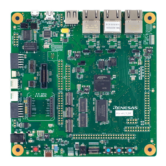
Renesas Starter Kit + for RZ/T2M, RZ/T2ME 3. Board Layout 3. Board Layout Component Layout Figure 3-1, Figure 3-3 below shows the top component layout of the board. USB to Serial Port Ethernet(ETH2) Ethernet(ETH1) USB Connector Connector Connector Ethernet(ETH0) J-Link® OB... - Page 13 Renesas Starter Kit + for RZ/T2M, RZ/T2ME 3. Board Layout USB FUNC Connector QSPI Flash NOR Flash Figure 3-2: Board Layout (Bottom side) R20UT4939EG0200 Rev. 2.00 Page 13 of 88 Apr 01, 2024...
-
Page 14: Board Dimensions
Renesas Starter Kit + for RZ/T2M, RZ/T2ME 3. Board Layout Board Dimensions Figure 3-3 below gives the board dimensions and connector positions. All the through-hole connectors are on a common 2.54mm pitch grid for easy interfacing. Figure 3-3: Board Dimensions... -
Page 15: Connectivity
Renesas Starter Kit + for RZ/T2M, RZ/T2ME 4. Connectivity 4. Connectivity Internal Board Connections The diagram below shows the CPU board components and their connectivity to the MPU. USB Type-C Regulator(5V-> 1.1V) NOR Flash(CS0) IC22 VCC18_PLL0/1 Regulator(5V-> 1.8V) DC Power Jack... -
Page 16: Emulator Connections
Renesas Starter Kit + for RZ/T2M, RZ/T2ME 4. Connectivity Emulator Connections Figure 4-2 below shows the connection between the CPU board, emulator and the host PC, Figure 4-3 ® below shows the connection between the CPU board, J-Link OB and the host PC. -
Page 17: User Circuitry
Renesas Starter Kit + for RZ/T2M, RZ/T2ME User Circuitry 5. User Circuitry Reset Circuit A reset control circuit is fitted to the CPU board to generate the required reset signal and is triggered from the RESET switch and the power-on-reset circuit. Refer to the RZ/T2M Group User’s Manual: Hardware for details regarding the reset signal timing requirements, and the CPU board schematics for information regarding the reset circuitry in use on the board. -
Page 18: Switches
Renesas Starter Kit + for RZ/T2M, RZ/T2ME User Circuitry Switches There are four push switches and four DIP switches located on the CPU board. The function of each switch and its connection is shown in Table 5-2 and Table 5-3. For further information regarding switch connectivity, refer to the CPU board schematics. -
Page 19: Leds
Renesas Starter Kit + for RZ/T2M, RZ/T2ME User Circuitry LEDs There are 20 LEDs on the RSK+ board. The function of each LED, its colour, and its connections are shown in Table 5-4. Table 5-4: LED Connections Colour Function Port... -
Page 20: Pmod
Renesas Starter Kit + for RZ/T2M, RZ/T2ME User Circuitry Pmod™ The RSK+ board is equipped with connectors for Digilent Pmod™ interface. Please connect the Pmod Peripheral module that is compatible with the PMOD connector. The Digilent Pmod™ Compatible headers use an SPI interface, an I C interface and a UART interface. -
Page 21: Grove
Renesas Starter Kit + for RZ/T2M, RZ/T2ME User Circuitry ® Grove ® ® The RSK+ board is equipped with connectors for Grove interface. Please connect the Grove module that is compatible with connector. ® The Grove compatible headers use an I C interface and an analog interface. -
Page 22: Qwiic
Renesas Starter Kit + for RZ/T2M, RZ/T2ME User Circuitry ® QWIIC ® ® The RSK+ board is equipped with connectors for QWIIC interface. Please connect the QWIIC products that is compatible with connector. ® ® The QWIIC compatible headers use an I C interface. -
Page 23: Mikrobus
Renesas Starter Kit + for RZ/T2M, RZ/T2ME User Circuitry mikroBUS™ The RSK+ board is equipped with connectors for mikroBUS™ interface. Please connect the mikroBUS™ products that is compatible with connector. The mikroBUS™ compatible headers use analog interface, SPI interface, UART interface, I C interface, PWM and interrupt. -
Page 24: Usb Serial Port
5.10 USB Serial Port A USB serial port is implemented in a Renesas low power microcontroller (RL78/G1C) and is connected to the RZ/T2M Serial Communications Interface (SCI) module. Connections between the USB to Serial converter and the microprocessor are listed in Table 5-12 below. -
Page 25: Ethernet
5.12 Ethernet When running any Ethernet software, a unique MAC address should be used. A unique Renesas allocated MAC address is attached to the PCB as a sticker and should always be used with this device to ensure full compatibility when using other Renesas hardware on a common Ethernet connection. - Page 26 Renesas Starter Kit + for RZ/T2M, RZ/T2ME User Circuitry Table 5-17: Ethernet Connections (ETH2) Ethernet signal Function Port ETH2_TXCLK RGMII: Transmit clock output P00_6 ETH2_TXEN RGMII: Transmit data enable / Transmit data error P00_2 ETH2_TXD0 RGMII: Transmit data0 P01_5 ETH2_TXD1...
-
Page 27: Ethernet Switch (Ethsw)
Renesas Starter Kit + for RZ/T2M, RZ/T2ME User Circuitry 5.13 Ethernet Switch (ETHSW) The CPU board has an Ethernet Switch (ETHSW) and is connected to the ETHSW module of the microprocessor. The ETHSW connections to and from the MPU are shown in Table 5-15, Table 5-16, Table 5-17, Table 5-18, Table 5-20 below. -
Page 28: Ethercat Slave Controller (Esc)
Renesas Starter Kit + for RZ/T2M, RZ/T2ME User Circuitry 5.14 EtherCAT Slave Controller (ESC) To run the EtherCAT slave controller software, the EtherCAT ID number is required. Please use SW3 as necessary. The CPU board has an EtherCAT slave controller (ESC) and is connected to the ESC module of the microprocessor. -
Page 29: Universal Serial Bus (Usb)
Renesas Starter Kit + for RZ/T2M, RZ/T2ME User Circuitry 5.15 Universal Serial Bus (USB) This CPU board is fitted with a USB Host socket (type A, CN10) and a Function socket (type Mini B, CN11). USB module is connected to the Host and Function socket and can operate as either a Host or Function device. -
Page 30: I 2 C Bus (Inter-Ic Bus)
Renesas Starter Kit + for RZ/T2M, RZ/T2ME User Circuitry 5.18 C Bus (Inter-IC Bus) The RZ/T2M features three I C (Inter-IC Bus) interface modules. Channel 0 of the IIC is connected to a 16Kbit EEPROM. Channel 0 of the IIC... -
Page 31: Configuration
Renesas Starter Kit + for RZ/T2M, RZ/T2ME Configuration 6. Configuration Modifying the RSK+ This section lists the option links that are used to modify the way CPU board operates in order to access different configurations. Configurations are made by modifying link resistors or headers with movable jumpers or by configuration DIP switches. - Page 32 Renesas Starter Kit + for RZ/T2M, RZ/T2ME Configuration 6.2.2 Trace Cut A trace-cut jumper is provided with a narrow copper trace connecting its pads. The silk screen overlay printing around a trace-cut jumper is a solid box. To isolate the pads, cut the trace between pads adjacent to each pad, then remove the connecting copper foil either mechanically or with the assistance of heat.
- Page 33 Renesas Starter Kit + for RZ/T2M, RZ/T2ME Configuration 6.2.4 Traditional Pin Header Jumpers These jumpers are traditional small pitch jumpers that require an external shunt to open/close them. following table describes the default settings for traditional pin header jumpers on the CPU board.
-
Page 34: Mpu Operating Modes
Renesas Starter Kit + for RZ/T2M, RZ/T2ME Configuration MPU Operating Modes Table 6-3 and Table 6-4 and Table 6-5 below details the option links associated with configuring the MPU Operating Modes. Table 6-3: MPU Operating Modes Switch Settings (1) SW4-1... -
Page 35: Emulator Configuration
Renesas Starter Kit + for RZ/T2M, RZ/T2ME Configuration Emulator Configuration 6.4.1 External Emulator Table 6-6 and Table 6-7 below details the function of the option links associated with External Emulator Configuration. Table 6-6: External Emulator Configuration Option Links (1) MPU Peripheral Selection... - Page 36 Renesas Starter Kit + for RZ/T2M, RZ/T2ME Configuration Table 6-7: External Emulator Configuration Option Links (2) MPU Peripheral Selection Destination Selection Signal name Interface Signal /Function IC22.E6 IC28.47 BSC_D06 IC23.11 BSC_D06_ (SW6-1 = ON) P21_7 JA3-A.23 TRACE_D6 IC28.46 CN9.18 TRACE_D6 (SW6-1 = OFF) CN3.7...
- Page 37 Renesas Starter Kit + for RZ/T2M, RZ/T2ME Configuration ® 6.4.2 J-Link ® Table 6-11 below details the function of the option links associated with J-Link OB Configuration. ® Table 6-11: J-Link OB Configuration Option Links MPU Peripheral Selection Destination Selection...
-
Page 38: Power Supply Configuration
Renesas Starter Kit + for RZ/T2M, RZ/T2ME Configuration Power Supply Configuration Table 6-13 below details the function of the option links associated with Power Supply Configuration. Table 6-13: Power Supply Configuration Option Links Reference Explanation 5.0V Connect 5V Power rail to 5.0V. -
Page 39: Analog Power & Adc Configuration
Renesas Starter Kit + for RZ/T2M, RZ/T2ME Configuration Analog Power & ADC Configuration Table 6-16 below details the function of the option links associated with Analog Power & ADC Configuration. Table 6-16: Analog Power & ADC Configuration Option Links MPU Peripheral Selection... -
Page 40: External Bus & Nor Flash Configuration
Renesas Starter Kit + for RZ/T2M, RZ/T2ME Configuration External BUS & NOR Flash Configuration Table 6-17, Table 6-18, Table 6-19, Table 6-20 below details the function of the option links associated with External BUS & NOR Flash Configuration. Table 6-17: External BUS & NOR Flash Configuration Option Links (1) - Page 41 Renesas Starter Kit + for RZ/T2M, RZ/T2ME Configuration Table 6-18: External BUS & NOR Flash Configuration Option Links (2) MPU Peripheral Selection Destination Selection Signal name Interface Signal /Function IC22.D6 IC29.39 BSC_A11 IC23.22 (SW6-1 = ON) BSC_A11_M1_UP P03_6 JA3-A.12 IC29.38 CN3.14...
- Page 42 Renesas Starter Kit + for RZ/T2M, RZ/T2ME Configuration Table 6-19: External BUS & NOR Flash Configuration Option Links (3) MPU Peripheral Selection Destination Selection Signal name Interface Signal /Function IC22.E1 IC29.56 BSC_A01 IC23.23 (SW6-1 = ON) JA3-A.2 BSC_A01_CAN_TX P05_3 CN1.18 IC29.55...
- Page 43 Renesas Starter Kit + for RZ/T2M, RZ/T2ME Configuration Table 6-20: External BUS & NOR Flash Configuration Option Links (4) MPU Peripheral Selection Destination Selection Signal name Interface Signal /Function IC22.H6 IC28.8 BSC_D05 IC23.10 (SW6-1 = ON) BSC_D05_GTIOC16B P21_6 JA3-A.22 IC28.9 GTIOC16B CN2.6...
-
Page 44: External Bus & Sdram Configuration
Renesas Starter Kit + for RZ/T2M, RZ/T2ME Configuration External BUS & SDRAM Configuration Table 6-22, Table 6-23, Table 6-24, Table 6-25 below details the function of the option links associated with External BUS & SDRAM Configuration. Table 6-22: External BUS & SDRAM Configuration Option Links (1) - Page 45 Renesas Starter Kit + for RZ/T2M, RZ/T2ME Configuration Table 6-23: External BUS & SDRAM Configuration Option Links (2) MPU Peripheral Selection Destination Selection Signal name Interface Signal /Function IC22.D2 IC29.50 BSC_A05 IC23.29 (SW6-1 = ON) BSC_A05_MD2 P04_7 JA3-A.6 BSC_A05_MD2 SW4.3 IC14.14...
- Page 46 Renesas Starter Kit + for RZ/T2M, RZ/T2ME Configuration Table 6-24: External BUS & SDRAM Configuration Option Links (3) MPU Peripheral Selection Destination Selection Signal name Interface Signal /Function IC22.F3 IC28.16 BSC_D09 IC23.44 (SW6-1 = ON) BSC_D09_TRACE_CLK F9 P22_2 JA3-A.30 IC28.17 TRACE_CLK CN9.6...
- Page 47 Renesas Starter Kit + for RZ/T2M, RZ/T2ME Configuration Table 6-25: External BUS & SDRAM Configuration Option Links (4) MPU Peripheral Selection Destination Selection Signal name Interface Signal /Function IC12.39 IC23.17 BSC_CAS# (SW6-1 = ON) JA3-A.49 IC12.39 BSC_CAS#_M P01_0 (SW6-1 = OFF), ETH2_MDIO IC16.50...
-
Page 48: Can Configuration
Renesas Starter Kit + for RZ/T2M, RZ/T2ME Configuration 6.10 CAN Configuration Table 6-28 below details the function of the option links associated with CAN Configuration. Table 6-28: CAN Configuration Option Links MPU Peripheral Selection Destination Selection Signal name Interface Signal /Function IC22.E1... -
Page 49: Ethernet Configuration
Renesas Starter Kit + for RZ/T2M, RZ/T2ME Configuration 6.11 Ethernet Configuration Table 6-31, Table 6-32, Table 6-33 below details the function of the option links associated with Ethernet Configuration. Table 6-31: Ethernet Configuration Option Links (1) MPU Peripheral Selection Destination Selection... - Page 50 Renesas Starter Kit + for RZ/T2M, RZ/T2ME Configuration Table 6-33: Ethernet Configuration Option Links (3) MPU Peripheral Selection Destination Selection Signal name Interface Signal /Function R85, ETH2_TXCLK CN23 IC16.37 (1-2 pin short) ETH2_TXCLK D3 P00_6 R85, CS5# CN23 JA3-A.27 R296...
-
Page 51: Ethernet Switch Configuration
Renesas Starter Kit + for RZ/T2M, RZ/T2ME Configuration 6.12 Ethernet Switch Configuration Table 6-31, Table 6-32, Table 6-33, Table 6-37 below details the function of the option links associated with Ethernet Switch (ETHSW) Configuration. Table 6-37: ETHSW Configuration Option Links... - Page 52 Renesas Starter Kit + for RZ/T2M, RZ/T2ME Configuration Table 6-39 and Table 6-40 below details the function of the jumpers associated with the ETHSW. Table 6-39: ETHSW Configuration Jumper Settings (1) Reference Jumper Position Explanation Shorted Pin 1-2 Connect 3.3V Power rail to VCC1833_2. (When using SDRAM)
-
Page 53: Ethercat Slave Controller Configuration
Renesas Starter Kit + for RZ/T2M, RZ/T2ME Configuration 6.13 EtherCAT Slave Controller Configuration Table 6-31, Table 6-32, Table 6-33, Table 6-41 below details the function of the option links associated with EtherCAT Slave Controller (ESC) Configuration. Table 6-41: ESC Configuration Option Links... - Page 54 Renesas Starter Kit + for RZ/T2M, RZ/T2ME Configuration Table 6-43 and Table 6-44 below details the function of the jumpers associated with the ESC. Table 6-43: ESC Configuration Jumper Settings (1) Reference Jumper Position Explanation Shorted Pin 1-2 Connect 3.3V Power rail to VCC1833_2. (When using SDRAM)
-
Page 55: General I/O & Led Configuration
Renesas Starter Kit + for RZ/T2M, RZ/T2ME Configuration 6.14 General I/O & LED Configuration Table 6-45 below details the function of the option links associated with General I/O & LED Configuration. Table 6-45: General I/O & LED Configuration Option Links... -
Page 56: Irq & Switch Configuration
Renesas Starter Kit + for RZ/T2M, RZ/T2ME Configuration 6.16 IRQ & Switch Configuration Table 6-47, Table 6-48, Table 6-49 below details the function of the option links associated with IRQ & Switch Configuration. Table 6-47: IRQ & Switch Configuration Option Links (1) - Page 57 Renesas Starter Kit + for RZ/T2M, RZ/T2ME Configuration Table 6-48: IRQ & Switch Configuration Option Links (2) MPU Peripheral Selection Destination Selection Signal name Interface Signal /Function IC4.2 POWER_RESET# IC38.11 RESET# U7.28 RESET_SW# J13.10 J20.10 CN9.9 DIP_SW1_18 Y18 P11_0 DIP_SW1_18 SW3.1...
- Page 58 Renesas Starter Kit + for RZ/T2M, RZ/T2ME Configuration Table 6-49: IRQ & Switch Configuration Option Links (3) MPU Peripheral Selection Destination Selection Signal name Interface Signal /Function J22.4 J25.2 SCI_TXD SW6-6 = ON SW6-5 = OFF JA2-A.6 P18_0 H16 P18_0 IC27.6...
-
Page 59: Mtu & Poe & Timer Configuration
Renesas Starter Kit + for RZ/T2M, RZ/T2ME Configuration 6.17 MTU & POE & Timer Configuration Table 6-50, Table 6-51 below details the function of the option links associated with MTU & POE & Timer Configuration. Table 6-50: MTU & POE & Timer Configuration Option Links (1) - Page 60 Renesas Starter Kit + for RZ/T2M, RZ/T2ME Configuration Table 6-51: MTU & POE & Timer Configuration Option Links (2) MPU Peripheral Selection Destination Selection Signal name Interface Signal /Function RLED1 R199 R200 LED1.A RLED1_M2_VP C20 P19_4 M2_VP R200 R199 JA5-A.21...
-
Page 61: Gpt & Poeg & Timer Configuration
Renesas Starter Kit + for RZ/T2M, RZ/T2ME Configuration 6.18 GPT & POEG & Timer Configuration Table 6-58 below details the function of the option links associated with GPT & POEG & Timer Configuration. Table 6-58: GPT & POEG & Timer Configuration Option Links... - Page 62 Renesas Starter Kit + for RZ/T2M, RZ/T2ME Configuration Table 6-59, Table 6-60, Table 6-61, Table 6-62, Table 6-63, Table 6-64 below details the function of the switches associated with the GPT & POEG & Timer. Table 6-59: GPT & POEG & Timer Configuration Switch Settings (1)
-
Page 63: Pmod (Uart) Configuration
Renesas Starter Kit + for RZ/T2M, RZ/T2ME Configuration 6.19 PMOD (UART) Configuration Table 6-65 below details the function of the option links associated with PMOD (UART) Configuration. Table 6-65: PMOD (UART) Configuration Option Links MPU Peripheral Selection Destination Selection Signal name... -
Page 64: Pmod (Spi) Configuration
Renesas Starter Kit + for RZ/T2M, RZ/T2ME Configuration 6.20 PMOD (SPI) Configuration Table 6-69 below details the function of the option links associated with PMOD (SPI) Configuration. Table 6-69: PMOD (SPI) Configuration Option Links MPU Peripheral Selection Destination Selection Signal name... -
Page 65: Grove ® (I 2 C) Configuration
Renesas Starter Kit + for RZ/T2M, RZ/T2ME Configuration ® 6.22 Grove C) Configuration ® Table 6-72 below details the function of the option links associated with Grove C) Configuration. ® Table 6-72: Grove C) Configuration Option Links MPU Peripheral Selection... -
Page 66: Qwiic
Renesas Starter Kit + for RZ/T2M, RZ/T2ME Configuration ® 6.24 QWIIC C) Configuration Table 6-75 below details the function of the option links associated with QWIIC® (I C) Configuration. ® Table 6-75: QWIIC C) Configuration Option Links MPU Peripheral Selection... -
Page 67: Mikrobus™ Configuration
Renesas Starter Kit + for RZ/T2M, RZ/T2ME Configuration 6.25 mikroBUS™ Configuration Table 6-77 below details the function of the option links associated with mikroBUS™ Configuration. Table 6-77: mikroBUS™ Configuration Option Links MPU Peripheral Selection Destination Selection Signal name Interface Signal... - Page 68 Renesas Starter Kit + for RZ/T2M, RZ/T2ME Configuration Table 6-78, Table 6-79, Table 6-80, Table 6-81, Table 6-82 below details the function of the switches associated with the mikroBUS™. Table 6-78: mikroBUS™ Configuration Switch Settings (1) SW6-1 Explanation Enable the external bus signal.
-
Page 69: Xspi & Qspi & Octa Flash Configuration
Renesas Starter Kit + for RZ/T2M, RZ/T2ME Configuration 6.26 xSPI & QSPI & Octa Flash Configuration Table 6-83 below details the function of the option links associated with xSPI & QSPI & Octa Flash Configuration. Table 6-83: xSPI & QSPI & Octa Flash Configuration Option Links... -
Page 70: Xspi & Hyperram Configuration
Renesas Starter Kit + for RZ/T2M, RZ/T2ME Configuration 6.27 xSPI & HyperRAM Configuration Table 6-85 below details the function of the option links associated with xSPI & HyperRAM Configuration. Table 6-85: xSPI & HyperRAM Configuration Option Links MPU Peripheral Selection... -
Page 71: Serial & Usb To Serial Configuration
Renesas Starter Kit + for RZ/T2M, RZ/T2ME Configuration 6.28 Serial & USB to Serial Configuration Table 6-86 below details the function of the option links associated with Serial & USB to Serial Configuration. Table 6-86: Serial & USB to Serial Configuration Option Links... -
Page 72: Serial & Rs485 Configuration
Renesas Starter Kit + for RZ/T2M, RZ/T2ME Configuration 6.29 Serial & RS485 Configuration Table 6-90 below details the function of the option links associated with Serial & RS485 Configuration. Table 6-90: Serial & RS485 Configuration Option Links (1) MPU Peripheral Selection... -
Page 73: Usb Configuration
Renesas Starter Kit + for RZ/T2M, RZ/T2ME Configuration 6.30 USB Configuration Table 6-96 below details the function of the option links associated with the USB Configuration. Table 6-96: USB Configuration Option Links MPU Peripheral Selection Destination Selection Signal name Interface... -
Page 74: Headers
7. Headers Application Headers This RSK+ board is fitted with application headers, which can be used to connect compatible Renesas application devices or as easy access to MPU pins. Table 7-1 below lists the connections of the application header, JA1-A. - Page 75 Renesas Starter Kit + for RZ/T2M, RZ/T2ME Headers Table 7-2 below lists the connections of the application header, JA2-A. Table 7-2: Application Header JA2-A Connections Application Header JA2-A Header Name Header Name MPU Pin MPU Pin Circuit Net Name Circuit Net Name...
- Page 76 Renesas Starter Kit + for RZ/T2M, RZ/T2ME Headers Table 7-3 below lists the connections of the BUS application header, JA3-A. Table 7-3: Application Header JA3-A Connections Application Header JA3-A (Bus) Header Name Header Name MPU Pin MPU Pin Circuit Net Name...
- Page 77 Renesas Starter Kit + for RZ/T2M, RZ/T2ME Headers Table 7-4 below lists the connections of the application header, JA5-A. Table 7-4: Application Header JA5-A Connections Application Header JA5-A Header Name Header Name MPU Pin MPU Pin Circuit Net Name Circuit Net Name...
- Page 78 Renesas Starter Kit + for RZ/T2M, RZ/T2ME Headers Table 7-5 below lists the connections of the application header, JA6. Table 7-5: Application Header JA6 Connections Application Header JA6 Header Name Header Name MPU Pin MPU Pin Circuit Net Name Circuit Net Name...
-
Page 79: Pin Headers
Renesas Starter Kit + for RZ/T2M, RZ/T2ME Headers Pin Headers This RSK+ board is equipped with a header that connects specific MPU pins separately from the application headers. Table 7-6 below lists the connections of the Pin header, CN1. The encoder interface signal of the MPU is connected to the Pin header, CN1. -
Page 80: Code Development
Renesas Starter Kit + for RZ/T2M, RZ/T2ME Code Development 8. Code Development Overview There are several ways to debug the code for this device: ® Connect CPU Board to PC through SEGGER development tool J-Link OB that is mounted on CPU Board. -
Page 81: Precautions For Use
Renesas Starter Kit + for RZ/T2M, RZ/T2ME Precautions for use 9. Precautions For Use About voltage conversion using level shifter Level shifters are used to connect signals between different voltage power domain in this board, but must be take care with the following signals. -
Page 82: Additional Information
Copyright This document may be, wholly or partially, subject to change without notice. All rights reserved. Duplication of this document, either in whole or part is prohibited without the written permission of Renesas Electronics Europe Limited. © 2024 Renesas Electronics Corporation. All rights reserved. -
Page 83: Appendix
Renesas Starter Kit + for RZ/T2M, RZ/T2ME 11. Appendix 11. Appendix Details on the placement of individual components on the board are shown on the next page. R20UT4939EG0200 Rev. 2.00 Page 83 of 88 Apr 01, 2024... - Page 84 ART FILM - ASSEMBLY_TOP ART FILM - ASSEMBLY_TOP...
- Page 85 ART FILM - ASSEMBLY_BOTTOM ART FILM - ASSEMBLY_BOTTOM...
- Page 86 Added 9 Precautions For Use, and subsequent chapter numbers has been shifted by one. 2.00 Apr 01, 2024 Cover This manual is made common, for Renesas Starter Kit+ for RZ/T2M and RZ/T2ME. ,misc. Added 1.1 Purpose introduces two types of RSK+ and should be read interchangeably. R20UT4939EG0200 Rev. 2.00...
- Page 87 RZ/T2M, RZ/T2ME Group , RZ/T2ME User’s Manual Renesas Starter Kit+ for RZ/T2M Publication Date: Rev.2.00 Apr 01, 2024 Published by: Renesas Electronics Corporation...
- Page 88 RZ/T2M, RZ/T2ME Group R20UT4939EG0200...
Need help?
Do you have a question about the RZ/T Series and is the answer not in the manual?
Questions and answers