
Related Manuals for XIMEA xiD MD028MU-SY


Summary of Contents for XIMEA xiD MD028MU-SY
- Page 1 [ksi-di: or sai-di:] • USB3.0 CCD camera series Technical Manual Version 1.05 September, 2019...
-
Page 2: Introduction
The purpose of this document is to provide a description of the XIMEA xiD-Series cameras and to describe the correct way to install related software and drivers and run it successfully. Please read this manual thoroughly before operating your new camera for the first time. -
Page 3: Standard Conformity
MD series sync cable, thread lock, 8-poles: ground, 2xTrigger In, 3 m long. Warning: Changes or modifications to the product may render it ineligible for operation under CE, FCC or other jurisdictions. XIMEA recommends using the above configuration to ensure compliance with the following standards: 1.3.1. -
Page 4: Genicam Gentl Api
GenICam GenTL API GenICam/GenTL GenICam standard transport layer interface, grabbing images. provides an agnostic transport layer interface to acquire images or other data and to communicate with a device. Each XIMEA camera can be GenTL Producer. 1.4. Helpful Links http://www.ximea.com/ Ximea Homepage •... -
Page 5: Table Of Contents
1.4.1. Table of Contents Introduction ................................2 1.1. About This Manual ............................. 2 1.2. About XIMEA ......................Error! Bookmark not defined. 1.2.1. Contact XIMEA ....................Error! Bookmark not defined. 1.3. Standard Conformity ............................3 1.3.1. CE Conformity ............................3 1.3.2. - Page 6 3.6.4. MD120xU-SY ............................27 3.6.4.1. Sensor and camera parameters ...................... 27 3.6.4.2. Quantum efficiency curves [%] ......................28 3.6.4.3. Dimensional drawings MD028xU-SY ....................29 3.6.4.4. Referenced documents ........................29 3.6.4.5. Sensor features ..........................29 3.7. User interface – LEDs ............................30 3.8.
- Page 7 Vision Library Integration ......................... 58 5.2. XIMEA CamTool ............................... 59 5.3. Supported Vision Libraries ..........................61 5.3.1. Libraries maintained by XIMEA ......................... 61 5.3.1.1. MathWorks MATLAB ........................61 5.3.1.2. MVTec HALCON ..........................61 5.3.1.3. National Instruments LabVIEW Vision Library ..................61 5.3.1.4.
- Page 8 Step 2 - Create Product Service Request (PSR) ..................75 6.2.3. Step 3 - Wait for PSR Approval ........................ 75 6.2.4. Step 4 - Sending the camera to XIMEA ..................... 75 6.2.5. Step 5 - Waiting for Service Conclusion ....................76 6.2.6.
-
Page 9: Xid Camera Series
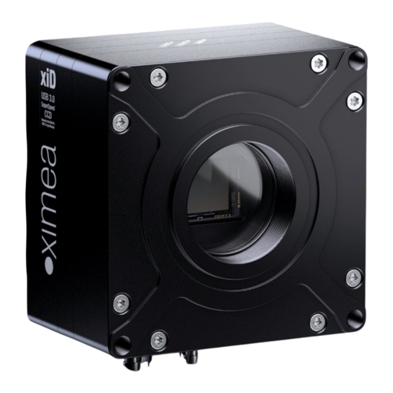
xiD Camera Series Figure 2-1 xiD camera. 2.1. What is xiD xiD [ cameras with newest Sony EXview HAD CCD II sensors (ICX674, ICX694, ICX814, ICX834) combined with ksi-di: or sai-di:] USB 3.0 interface - designed with consideration for the Scientific applications: •... -
Page 10: Xid Camera Applications
2.3. xiD Camera Applications • Astronomy and Astrography • Factory and industry automation - where high resolution or NIR is required • Ophthalmology and Retinal imaging • Material and Life science • Medical Imaging and Light Microscopy • Pharmaceutics and Healthcare •... -
Page 11: Model Nomenclature
2.5. Model Nomenclature Part number convention for the different models: xiD family MDxxxyU-zz-OPT xiD family name xxx: Resolution in 0.1 MPixel. E.g. 2.8 MPixel Resolution: xxx = 028 y=C: color model y=M: black & white model Uncooled Vendor of the sensor zz = SY: SONY [-OPT]: Options OPT = BRD: board level camera... -
Page 12: Models Overview, Sensor And Models
2.6. Models Overview, sensor and models Sensor Pixel Sensor Model Resolution size [bit] diagonal MD028MU-SY SONY ICX674ALG 1934 x 1456 4.54 µm 68.6 dB 11 mm 56.9 MD028CU-SY Color SONY ICX674AQG MD061MU-SY SONY ICX694ALG 2754 x 2204 4.54 µm 68.7 dB 16 mm 28.4 MD061CU-SY... -
Page 13: Accessories
Y-Shaped Power USB3 Cable 3.0m, Up Angle thumbscrews CBL-U3-5M0-YP Y-Shaped Power USB3 Cable 5.0m, thumbscrews CBL-U3-5M0-YP-UA Y-Shaped Power USB3 Cable 5.0m, Up Angle, thumbscrews table 2-4, accessories Note: 1) For more information please visit: https://www.ximea.com/support/projects/usb3/wiki/USB_3_Host_Adapters xiD - Technical Manual Version.1.05... -
Page 14: Hardware Specification
-400 to 400 % Gamma 0.3 to 1.0 Full color correction matrix (3+1)x3 coefficients ranges -3.9 to 3.9 table 3-2, firmware / API features XIMEA support pages: http://www.ximea.com/support More details on API/SDK features are available at xiD - Technical Manual Version.1.05... -
Page 15: Lens Mount
3.3. Lens Mount The xiD cameras C-mount lenses. figure 3-1, xiD lens mount 3.4. Mounting points Mounting points available to the customer are shown below. All are M4 thread. Figure 3-2, drawing demonstrating the mounting hole positions. 3.5. Optical path A filter glass is part of the optical path of the camera. -
Page 16: Monochrome And Near Infrared Extended Camera Models
3.5.1. Monochrome and near infrared extended camera models Used filter brand BK7 AR2x Thickness 1.0±0.1 mm Coating Anti-reflex both sides table 3-3, monochrome camera - filter glass parameter BK7 AR2x - Transmission Curve 350 400 450 500 550 600 650 700 750 800 850 900 950 1000 1050 Wavelength (nm) figure 3-4, monochrome camera - filter glass transmission curve xiD - Technical Manual Version.1.05... -
Page 17: Color Camera Models
3.5.2. Color camera models Used filter brand ICR650 Thickness 1.0±0.1 mm Coating table 3-4, color camera - filter glass parameter ICR650 - Transmission Curve 350 400 450 500 550 600 650 700 750 800 850 900 950 1000 1050 Wavelength (nm) figure 3-5, color camera - filter glass transmission curve xiD - Technical Manual Version.1.05... -
Page 18: Model Specific Characteristics
3.6. Model Specific Characteristics 3.6.1. MD028xU-SY 3.6.1.1. Sensor and camera parameters xiD model MD028CU-SY MD028MU-SY Sensor parameter ICX674AQG ICX674ALG Part number Color filter RGB Bayer mosaic None Type CCD progressive scan Pixel Resolution (W x H) [pixel] 1934 x 1456 Active area size (W x H) [mm] 8.78 x 6.61mm... -
Page 19: Quantum Efficiency Curves [%]
Binning(readout) TAPs MD028CU-SY MD028MU-SY Pixels Bit/px Color 1936 x 1456 15.8 966 x 726 28.7 644 x 482 39.3 482 x 360 48.3 384 x 288 55.9 Color 1936 x 1456 28.7 966 x 726 48.2 644 x 482 62.5 482 x 360 73.3 384 x 288... -
Page 20: Dimensional Drawings Md028Xu-Sy
3.6.1.3. Dimensional drawings MD028xU-SY figure 3-7, dimensional drawing MD028xU-SY 3.6.1.4. Referenced documents ICX674 Datasheets, Sony Corp. 3.6.1.5. Sensor features feature Note Binning Yes, up to 5x5 Skipping Vertical cropping results in increased read speed. HW Trigger Trigger without overlap Not available table 3-7, sensor features available xiD - Technical Manual Version.1.05... -
Page 21: Md061Xu-Sy
3.6.2. MD061xU-SY 3.6.2.1. Sensor and camera parameters xiD model MD061CU-SY MD061MU-SY Sensor parameter ICX694AQG ICX694ALG Part number Color filter RGB Bayer mosaic None Type CCD progressive scan Pixel Resolution (W x H) [pixel] 2752 x 2204 Active area size (W x H) [mm] 12.5 x 10.0mm Sensor diagonal... -
Page 22: Quantum Efficiency Curves [%]
Binning(readout) TAPs MD061CU-SY MD061MU-SY Pixels Bit/px Color 2752 x 2204 1372 x 1100 14.3 912 x 732 20.0 684 x 548 25.0 548 x 438 29.4 Color 2752 x 2204 14.3 1372 x 1100 25.0 912 x 732 33.4 684 x 548 40.1 548 x 438 45.8... -
Page 23: Dimensional Drawings Md061Xu-Sy
3.6.2.3. Dimensional drawings MD061xU-SY figure 3-9, dimensional drawing MD061xU-SY 3.6.2.4. Referenced documents ICX694 Datasheets, Sony Corp. 3.6.2.5. Sensor features feature Note Binning Yes, up to 5x5 Skipping Vertical cropping results in increased read speed. HW Trigger Trigger without overlap Not available table 3-10, sensor features available xiD - Technical Manual Version.1.05... -
Page 24: Md091Xu-Sy
3.6.3. MD091xU-SY 3.6.3.1. Sensor and camera parameters xiD model MD091CU-SY MD091MU-SY Sensor parameter ICX814AQG ICX814ALG Part number Color filter RGB Bayer mosaic None Type CCD progressive scan Pixel Resolution (W x H) [pixel] 3384 x 2708 Active area size (W x H) [mm] 12.5 x 10.0mm Sensor diagonal... -
Page 25: Quantum Efficiency Curves [%]
Binning(readout) TAPs MD091CU-SY MD091MU-SY Pixels Bit/px Color 3384 x 2708 1690 x 1352 1124 x 900 13.8 842 x 674 17.5 672 x 538 20.8 Color 3384 x 2708 1690 x 1352 17.5 1124 x 900 23.7 842 x 674 28.9 672 x 538 33.2... -
Page 26: Dimensional Drawings Md091Xu-Sy
3.6.3.3. Dimensional drawings MD091xU-SY figure 3-11, dimensional drawing MD091xU-SY 3.6.3.4. Referenced documents ICX814 Datasheets, Sony Corp. 3.6.3.5. Sensor features feature Note Binning Yes, up to 5x5 Skipping Vertical cropping results in increased read speed. HW Trigger Trigger without overlap Not available table 3-13, sensor features available xiD - Technical Manual Version.1.05... -
Page 27: Md120Xu-Sy
3.6.4. MD120xU-SY 3.6.4.1. Sensor and camera parameters xiD model MD120CU-SY MD120MU-SY Sensor parameter ICX834AQG ICX834ALG Part number Color filter RGB Bayer mosaic None Type CCD progressive scan Pixel Resolution (W x H) [pixel] 4244 x 2832 Active area size (W x H) [mm] 13.16 x 8.78mm Sensor diagonal... -
Page 28: Quantum Efficiency Curves [%]
Binning(readout) TAPs MD120CU-SY MD120MU-SY Pixels Bit/px Color 4244 x 2832 2120 x 1414 1412 x 942 10.9 1056 x 704 14.0 844 x 562 16.7 Color 4244 x 2832 2120 x 1414 14.0 1412 x 942 19.2 1056 x 704 23.8 844 x 562 27.7... -
Page 29: Dimensional Drawings Md028Xu-Sy
3.6.4.3. Dimensional drawings MD028xU-SY figure 3-13, dimensional drawing MD120xU-SY 3.6.4.4. Referenced documents ICX834 Datasheets, Sony Corp. 3.6.4.5. Sensor features feature Note Binning Yes, up to 5x5 Skipping Vertical cropping results in increased read speed. HW Trigger Trigger without overlap Not available table 3-16, sensor features available xiD - Technical Manual Version.1.05... -
Page 30: User Interface - Leds
3.7. User interface – LEDs Three status LEDs are located on the back of the cameras, please see below. figure 3-14, position status LEDs The LEDs are programmable. Please note the following description: Color Defaults Note POWER Orange User configurable STATUS2 Green Connection status... -
Page 31: Xid Usb 3.0 Interface
3.8. xiD USB 3.0 Interface Connector Signals Mating Connectors USB 3.0 Standard USB 3.0 Micro-B Female Connector Standard USB 3.0 Micro-B Connector with thumbscrews Screw thread M2, thread distance 18.0mm table 3-19, USB 3.0 mating connector description The USB 3.0 Micro-B connector is used for data transmission, camera control and power. 3.8.1. -
Page 32: Digital Input / Output (Gpio) Interface
Mating Connectors Opto-isolated trigger input and insulated fast TTL HDR-E14 MAG1+ I/O 14-pin HDR-E14-MSG1+ IO pigtail cable Ximea PN: CBL-MD-PWR-SYNC-3M0 table 3-21, GPIO mating connector description 3.9.1. Location IO interface receptacle is located on the underside of the camera close to USB 3.0 connector: figure 3-17, position GPIO + power connector 3.9.2. - Page 33 I/O connector Pin Assignment: Name Signal Technical description GPO1X Digital Output 1 pole X 24V logic output (relay switch) GPO1Y Digital Output 1 pole Y 24V logic output (relay switch) GPI1+ Digital Input 1 positive pole (<0.8 Low; 4-24 High) GPI1- Digital Input 1 negative pole (<0.8 Low;...
-
Page 34: Optically Isolated Digital Input
3.9.3. Optically isolated Digital Input 3.9.3.1. Optically isolated Digital Input - General info Item Parameter / note Maximal input voltage Common pole Effect of incorrect input terminal connection Reverse voltage polarity protected Effects when withdrawing/inserting input No damage, no lost data module under power Maximum recommended cable length Input level for logical 0... -
Page 35: Digital Input - Internal Schematic
3.9.3.3. Digital Input – Internal Schematic The internal scheme of Digital Input signal flow inside the camera is below. figure 3-19, digital input, interface schematic 3.9.3.4. Digital Input – Wiring Power Supply PLC Device Common Camera Input Output GND (Common IO Ground) figure 3-20, digital input, interface wiring xiD - Technical Manual Version.1.05... -
Page 36: Digital Input - Timing
3.9.3.5. Digital Input – Timing Typical measured input delay between Digital Input to FPGA Input Measurements of input delays: Edge Type Input Voltage [V] Typ. delay [μs] Rising Rising Falling Falling Falling table 3-25, digital input, timing Note: Measured at: Ambient Temperature 25°C 3.9.4. -
Page 37: Digital Output - Wiring
3.9.4.4. Digital Output – Wiring Digital output operates as relay. In most cases a power source for external device must be provided. Connecting Digital OUTPUT to a NPN-compatible PLC device input (biased) Output state Output switch state Input state Sourcing current Pull up (energized) Relaxing Not energized... - Page 38 Power Supply Camera PLC Device GPO1X GPO1Y figure 3-24, Connecting Digital OUTPUT to a NPN-compatible PLC device - single input Connecting Digital OUTPUT to a PNP-compatible device Output state Output switch state Input state Sinking current Not energized Relaxing Pull up (energized) figure 3-25, Connecting Digital OUTPUT to a PNP-compatible device −...
- Page 39 Output Wiring Example: LED Driving LED can be driven directly by camera digital output. A series resistor must be used to limit LED current. figure 3-26, LED Driving − − output LED series resistor can be calculated by the following equation: Where: power supply voltage (5V to 24V) voltage across digital output pins (see.
- Page 40 Output Wiring Example: Inductive load (Relay) Driving Do not connect inductive load RL directly to Camera Digital Output. A transistor must be used to prevent damage of the output. See image below for possible inductive load driving. Resistor R can be connected to Digital Outputs and power supply to provide the necessary bias current for transistor.
-
Page 41: Isolated High Speed Digital Lines (Gpi2, Gpo2)
3.9.5. Isolated High Speed Digital Lines (GPI2, GPO2) xiD camera features one input and one output with fast digital isolation Non isolated Digital lines can be used as inputs or outputs compatible with TTL logic. These are high impedance pins so when used as output high impedance slave input has to be used. -
Page 42: Cbl-U3-1M0 / Cbl-U3-3M0 / Cbl-U3-5M0
3.10. CBL-U3-1M0 / CBL-U3-3M0 / CBL-U3-5M0 1.0m / 3.0m / 5.0m USB 3.0 cables As per Customer Requirements (max. 10M recommended) figure 3-30, drawing USB3 cable Item Description USB A 3.0 9 pin Molded Plug <BLK> MCD-USB-211 [OD= 7.3mm] <BLK> 3 USB MicB 3.0 sl 10 pin Molded Plug with Screw Locking <BLK>... -
Page 43: Cbl-U3-3M0-Ang
3.11. CBL-U3-3M0-ANG 3.0m USB 3.0 cable, angled micro USB3 connector As per Customer Requirements (max. 3M recommended) 36.5 23.5 30mm Ref. 30mm Ref. x.xxM XYZ x.xxM XYZ 21.75 +0.2 figure 3-33, drawing USB3 cable angled Item Description USB A 3.0 9 pin Molded Plug <BLK> A12-7143 [OD=5.9mm] <BLK>... -
Page 44: Cbl-U3-3M0-Yp / Cbl-U3-5M0-Yp
3.12. CBL-U3-3M0-YP / CBL-U3-5M0-YP 3.0m / 5.0m USB 3.0 Y-cables providing additional power from secondary USB port. figure 3-36, drawing USB3 cable figure 3-37, wiring USB3 cable Signal Description VBUS Power USB 2.0 signal pair OTG Identification Power Ground MicB_SSTX- USB 3.0 SuperSpeed transmitter signal pair MicB_SSTX+ GND_DRAIN... -
Page 45: Cbl-U3-3M0-Yp-Ua / Cbl-U3-5M0-Yp-Ua
3.13. CBL-U3-3M0-YP-UA / CBL-U3-5M0-YP-UA 3.0m USB 3.0 Y-cables providing additional power from secondary USB port. Featuring angled micro USB3 connector. figure 3-38, drawing USB3 cable angled figure 3-39, wiring USB3 cable angled Signal Description VBUS Power USB 2.0 signal pair OTG Identification Power Ground MicB_SSTX-... -
Page 46: Usb 3 Host Adapters
3.14. USB 3 host adapters USB 3.0 to PCI Express x1 Gen2 Host Card figure 3-40, USB3 host adapters https://www.ximea.com/support/projects/usb3/wiki/USB_3_Host_Adapters Please refer to following page for more information. System requirements All requirements depend on selected host adapter. Please refer to host adapter specification... -
Page 47: Cbl-Md-Pwr-Sync-3M0
3.15. CBL-MD-PWR-SYNC-3M0 The following is a description of the sync cable for the xiD camera line. Cable drawing figure 3-41, drawing sync cable – current revisions of this cable are 3m in length color Signal Blue GPO1X - Opto-isolated Output Green GPO1Y - Opto-isolated Output Violet... -
Page 48: Tripod Adapter - Mech-60Mm-Bracket-T
3.16. Tripod Adapter – MECH-60MM-BRACKET-T xiD series tripod mounting bracket figure 3-43, mounting tripod adapter Use 4x M4 screws provided with bracket as a kit for mounting. Bracket can be mounted on the bottom of camera. 3.16.1. Dimensional drawings figure 3-44, dimensional drawing tripod adapter xiD - Technical Manual Version.1.05... -
Page 49: Operation
4.1.2. Hardware Requirements The XIMEA xiD cameras are compatible with USB 3.1, USB 3.0. Please note, that the highest performance can only be achieved by using high performance USB 3.1 or USB 3.0 ports. Please note details and the most recent info at: Recommended hardware http://www.ximea.com/support/wiki/usb3/Compatible_hardware... -
Page 50: Usb 3.1 Host Adapter
The USB 3.1 Gen1 cable that you use with the xiD camera is responsible for the power supply and the data transfer to the PC. It is required to use an industrial USB 3.1 Gen1 cable with a proper wiring and shielding. We recommend using XIMEA industrial USB 3.1 Gen1 cables in order to achieve the maximum possible performance of the camera. -
Page 51: Video Formats
4.2. Video Formats 4.2.1. Full Resolution By default, each camera outputs a full resolution image based on its sensor specification. 4.2.2. ROIs – Region Of Interest ROI, also called area-of-interest (AOI) or windowing, allows the user to specify a sub-area of the original sensor size for read-out. Depending on the sensor inside xiD cameras support the definition of one single ROI by specifying the size (width and height) as well as the position (based on upper left corner) of the of the sub-area. -
Page 52: Image Data Output Formats
4.2.4. Image Data Output Formats All modes are provided by the xiAPI or standard interfaces using the xiAPI (please note 5.1 Accessing the Camera). Each xiD camera supports several Image Data Output Formats. Mode Description RAW8 Raw sensor data, 8 Bit per pixel, single channel RAW16 Raw sensor data, 16 Bit per pixel, single channel 10,12 or 14 Bit sensor output (LSB) with bit-shift up to 16 Bit... -
Page 53: Acquisition Modes
Only then, the exposure of first frame is started, which is followed by the data readout. XIMEA cameras supports several triggered modes along with single image exposure after one trigger. The trigger signal can be either edge sensitive or level sensitive. -
Page 54: Triggered Mode Without Overlap - Single Frame
4.3.2.1. Triggered mode without overlap - single frame This mode gives lower FPS compared to Free-Run mode and lower FPS. figure 4-2, acquisition mode – triggered without overlap In this mode the timing depends on sum of: • Input transition time (t ), depends on: o Digital Input Delay - time for changing internal circuit to active state. -
Page 55: Triggered Acquisition - Burst Of Frames
If trigger is level sensitive it can be used to control image acquisition. This mode is available only if the camera is set to frame rate mode. figure 4-4, triggered burst of frames – frame burst active (maximal frame rate) Frame Burst Modes: https://www.ximea.com/support/wiki/allprod/Frame_Burst_Modes Please see: xiD - Technical Manual Version.1.05... -
Page 56: Camera Parameters And Features
4.4. Camera Parameters and Features 4.4.1. Exposure Time Also known as shutter speed. This parameter defines the length of the integration period for each frame. Most CMOS sensors generate the exposure interval internally. For some it is possible to control it by external signaling. The sensor internal timing depends on the provided system clock. -
Page 57: Color Correction Matrix
4.5.5. Color Correction Matrix The color correction matrix is a 4x4-matrix which is applied on each pixel of an image in a host-assisted port-processing step. For example, this Matrix can be used to adjust the brightness, contrast, and saturation. 4.5.6. Sensor Defect Correction During the manufacturing process, every camera is tested for various type of defects and a list of the measured defect pixels is created and stored in the camera’s non-volatile memory. -
Page 58: Software
5.1.1. Proprietary API All XIMEA cameras are supported by the same unified APIs (application programming interface). The API is a software interface between the camera system driver and the application. Different APIs are available for different programming environments, e.g. xiAPI (see 5.7.1 XIMEA APIs) for C/C++ developments and xiAPI.Net for C#/.Net based developments 5.1.2. -
Page 59: Ximea Camtool
5.2. XIMEA CamTool The CamTool is a cross-platform application showcasing the features of all XIMEA camera families. Short description It runs on Windows, Linux, macOS systems offering a substantial imaging tool set, which can be further extended with custom modules using a plugin infrastructure. CamTool is based on Qt for the UI and xiAPI for the camera control. Its camera settings... - Page 60 Functions • to see live image from multiple XIMEA cameras connected • control the camera parameters • store of camera image and video • analyze the image properties • histogram and line profile • image averaging, image flip/mirror • software trigger timer, save/load camera and program settings •...
-
Page 61: Supported Vision Libraries
Libraries maintained by XIMEA All cameras listed in the section Products are supported with these libraries. XIMEA commits to update the API within twelve months after a new major release. XIMEA warranties backwards compatibility of these software packages for two major releases. -
Page 62: Ximea Windows Software Package
Microsoft Windows 7 Embedded), Microsoft Windows Server 2008 R2. 5.4.1. Contents The package contains: • OS Drivers of all XIMEA camera types for OS Microsoft Windows 7 SP1 32/64 bit, Windows 8 32/64 bit, Windows Server 2008 R2 x86-64, Windows 10 32/64 bit. xiAPI xiAPI.NET xiApiPtyhon •... - Page 63 Select the Software components you want to install. You can uncheck the components you don't want to install, but it is recommended to leave them all checked. figure 5-3, XIMEA Windows Software Package installation - 2 • Specify the install location - you can leave the default location or change it to your desired location.
- Page 64 • Now the XIMEA API Software Package should start copying files, updating System Variables and installing drivers if necessary. figure 5-5, xiAPI installation, Windows - 4 • Installation is completed. figure 5-6, xiAPI installation, Windows - 5 • Finish. xiD - Technical Manual Version.1.05...
-
Page 65: Ximea Linux Software Package
5.5. XIMEA Linux Software Package XIMEA Linux Software Package is tarred installer with files that can be run on Linux Ubuntu 14.04 and 16.04 (32 and 64 Bit) and newer releases. 5.5.1. Contents The package contains: • Driver (beta version) for XIMEA USB2 and USB3 cameras •... - Page 66 5-8, XIMEA Linux Software Package installation - 2 Note: If logged in user is not root, you will be asked for your password to get root access, because the installation runs with root account using sudo. xiD - Technical Manual Version.1.05...
-
Page 67: Ximea Macos Software Package
5.6. XIMEA macOS Software Package XIMEA macOS Software Package is native DMG installer that can be run on macOS 10.8 (Mountain Lion) or newer. 5.6.1. Contents The package contains: • Driver (beta version) for XIMEA USB2 and USB3 cameras •... -
Page 68: Start Ximea Camtool
On the General Tab select the option Anywhere under Allow applications downloaded from: figure 5-10, xiAPI installation, MacOS - 2 XIMEA macOS Software. Package: http://www.ximea.com/downloads/recent/XIMEA_OSX_SP.dmg • Download • Mount it by double-clicking this file in Finder. • Run the install script to install XiAPI on your macOS system •... -
Page 69: Programming
• – Integrated API into PYTHON. 5.7.2. xiAPI Overview xiAPI stands for XIMEA Application Programming Interface. It is a common interface for all XIMEA cameras. Architecture API is a software interface between the camera system driver and application. • On Windows: xiAPI is compiled into xiapi32.dll or xiapi64.dll •... -
Page 70: Xiapi Parameters Description
For a complete list of available parameter, please visit the xiAPI online manual at http://www.ximea.com/support/wiki/apis/XiAPI_Manual Note: Since xiAPI is a unified programming interface for all of XIMEA‘s cameras, not all of the described parameters apply for every camera and sensor model. -
Page 71: Acquire Images
5.7.5.3. Acquire Images This example shows how the acquisition is started on the device with the handle xiH, ten images are acquired in a row and the acquisition is stopped. xiStartAcquisition(xiH); #define EXPECTED_IMAGES 10 for (int images=0;images < EXPECTED_IMAGES;images++) // getting image from camera xiGetImage(xiH, 5000, &image);... -
Page 72: Genicam
It is important to set this parameter to XI_OFF to ensure highest possible data transfer speed. To disable ABC, the application should set parameter XI_PRM_AUTO_BANDWIDTH_CALCULATION to XI_OFF before the first xiOpenDevice is used. This setting disabled ABC and the camera stream is not limited. 5.7.7. -
Page 73: Ximea Control Panel
5.8. XIMEA Control Panel The XIMEA Control Panel (xiCOP), is a diagnostics and management tool for all XIMEA cameras. xiCOP is currently only available for Windows operating system. figure 5-12, xiCOP Features • Facilitates diagnostics of system performance bottlenecks. xiCOP is capable of retrieving the system’s hardware tree, thus problematic hardware configurations can be identified. -
Page 74: Appendix
XIMEA xiCOP software (please see 5.8 XIMEA Control Panel). It will immediately start searching for connected cameras. Your camera will appear in the XIMEA camera list on the upper left side of the xiCOP window if it is connected properly and your USB interface meets the minimum system requirements described in 4.1 System Requirements. -
Page 75: What Is The Real Transfer Speed
In order to reliably achieve maximum transfer speed it is necessary to verify that you are using recommended hardware (please see 4.1 System Requirements), and that all software requirements are met. xiCOP (please see 5.8 XIMEA Control Panel) - XIMEA Control Panel free software tool, facilitates the task of verification of XIMEA camera installations. -
Page 76: Step 5 - Waiting For Service Conclusion
Step 5 - Waiting for Service Conclusion Once we have received the camera, we will send you a notification. The XIMEA Service will then check the status of the camera that you have sent for a possible repair. Depending on warranty conditions, product status and agreement one of the following... -
Page 77: Recommended Light Conditions
6.3.6. Recommended light conditions. Do not expose the camera to light sources with intense energy, e.g. laser beams or X-ray. Light intensity or exposure time exceeding the saturation of the sensor may damage the sensor irreparably. This may occur e.g. in the following situations: •... -
Page 78: Protect The Optical Components
XIMEA warrants to the Original Purchaser that the Camera provided is guaranteed to be free from material and manufacturing defects for a period of two years. Should a unit fail during this period, XIMEA will, at its option, repair or replace the damaged unit. -
Page 79: Disclaimer Of Warranty
XIMEA does not assume any liability for damage that is the result of improper use of its products or failure to comply with the operating manuals or the applicable rules and regulations. - Page 80 3. The Purchaser has the non-exclusive right to use standard software and firmware, provided that it remains unchanged, is used within the agreed performance parameters, and on the agreed equipment. Without express agreement the Purchaser may make one back-up copy of standard software. 4.
- Page 81 Article IV: Time for Supplies; Delay 1. Times set for Supplies shall only be binding if all Documents to be furnished by the Purchaser, necessary permits and approvals, especially concerning plans, are received in time and if agreed terms of payment and other obligations of the Purchaser are fulfilled.
- Page 82 3. Prior to assembly or erection, the materials and equipment necessary for the work to start must be available on the site of assembly or erection and any preparatory work must have advanced to such a degree that assembly or erection can be started as agreed and carried out without interruption.
- Page 83 1. Unless otherwise agreed, the Supplier shall provide the Supplies free from third parties' industrial property rights and copyrights (hereinafter referred to as "IPR") with respect to the country of the place of delivery only. If a third party asserts a justified claim against the Purchaser based on an infringement of an IPR by the Supplies made by the Supplier and used in conformity with the contract, the Supplier shall be liable to the Purchaser within the time period stipulated in Article VIII No.
-
Page 84: Copyright
(f) negligent injury to life, limb or health; or (g) negligent breach of a fundamental condition of contract (“wesentliche Vertragspflichten”). However, claims for damages arising from a breach of a fundamental condition of contract shall be limited to the foreseeable damage which is intrinsic to the contract, provided that no other of the above case applies. -
Page 85: Glossary
Glossary Term /Abbreviation Definition Analog to Digital Converter Application Programming Interface AR (coating) Anti-Reflex B/W or B&W Black and White Charge-Coupled Device Correlated double sampling CMOS Complementary Metal Oxide Semiconductor Do not connect DSNU Dark Signal non-Uniformity Dynamic Range Electro Magnetic Compatibility Electronic rolling shutter Fixed pattern noise Frame per second... -
Page 86: List Of Figures
list of figures Figure 2-1 xiD camera. figure 3-1, xiD lens mount Figure 3-2, drawing demonstrating the mounting hole positions. figure 3-3, Optical path section figure 3-4, monochrome camera - filter glass transmission curve figure 3-5, color camera - filter glass transmission curve figure 3-6, ICX674-mono, color;... - Page 87 4-4, triggered burst of frames – frame burst active (maximal frame rate) figure 5-1, CamTool Layout figure 5-2, XIMEA Windows Software Package installation - 1 figure 5-3, XIMEA Windows Software Package installation - 2 figure 5-4, XIMEA Windows Software Package installation - 3...
-
Page 88: List Of Tables
list of tables table 2-1, advantages table 2-2, common features table 2-3, models overview table 2-4, accessories table 3-1, environment table 3-2, firmware / API features table 3-3, monochrome camera - filter glass parameter table 3-4, color camera - filter glass parameter table 3-5, MD028xU-SY, sensor and camera parameters table 3-6, MD028xU-SY, standard readout modes table 3-7, sensor features available... - Page 89 XIMEA GmbH Am Mittelhafen 16 • 48155 Münster • Germany • www.ximea.com © Copyright 2019, XIMEA GmbH, All rights reserved...
Need help?
Do you have a question about the xiD MD028MU-SY and is the answer not in the manual?
Questions and answers