
Related Manuals for XIMEA xiQ Series


Summary of Contents for XIMEA xiQ Series
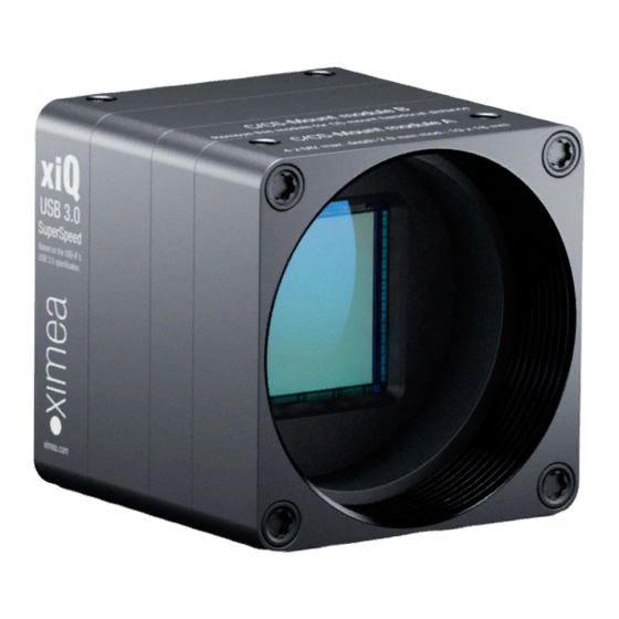
- Page 1 [ksi-kju: or sai-kju:] • USB 3.0 camera series Technical Manual Version 1.35, September, 2019...
-
Page 2: Introduction
The purpose of this document is to provide a description of the XIMEA xiQ-Series cameras and to describe the correct way to install related software and drivers and run it successfully. Please read this manual thoroughly before operating your new camera for the first time. -
Page 3: Standard Conformity
A shielded I/O Sync cable ref. CBL-MQSYNC-3M0 (3m) Warning: Changes or modifications to the product may render it ineligible for operation under CE, FCC or other jurisdictions. XIMEA recommends using the above configuration to ensure compliance with the following standards: 1.3.1. -
Page 4: Genicam Gentl Api
GenICam GenTL API GenICam/GenTL GenICam standard transport layer interface, grabbing images. provides an agnostic transport layer interface to acquire images or other data and to communicate with a device. Each XIMEA camera can be GenTL Producer. 1.4. Helpful Links •... -
Page 5: Table Of Contents
1.4.1. Table of Contents Introduction ................................2 1.1. About This Manual ............................. 2 1.2. About XIMEA ......................Error! Bookmark not defined. 1.2.1. Contact XIMEA ....................Error! Bookmark not defined. 1.3. Standard Conformity ............................3 1.3.1. CE Conformity ............................3 1.3.2. - Page 6 3.5.2.3. Drawings (C-mount [with C/CS mount module B]) ................24 3.5.2.4. Drawings board level ........................24 3.5.2.5. Referenced documents ........................25 3.5.2.6. Sensor features ..........................25 3.5.2.7. Note: horizontal image lines (MQ013CG-E2, MQ013MG-E2) ............. 25 3.5.2.8. Note: triggered exposure ........................ 25 3.5.3.
- Page 7 3.9.3.1. Digital Input - General info ......................44 3.9.3.2. Digital Input – Wiring ........................44 3.9.3.3. Digital Input – 24V logic ......................... 45 3.9.3.4. Digital Input – 5V logic ........................46 3.9.4. Digital Output ............................47 3.9.4.1. Digital Output - General info ......................47 3.9.4.2.
- Page 8 Vision Library Integration ......................... 79 5.2. XIMEA CamTool ............................... 80 5.3. Supported Vision Libraries ..........................82 5.3.1. Libraries maintained by XIMEA ......................... 82 5.3.1.1. MathWorks MATLAB ........................82 5.3.1.2. MVTec HALCON ..........................82 5.3.1.3. National Instruments LabVIEW Vision Library ..................82 5.3.1.4.
- Page 9 Step 2 - Create Product Service Request (PSR) ..................97 6.2.3. Step 3 - Wait for PSR Approval ........................ 97 6.2.4. Step 4 - Sending the camera to XIMEA ..................... 97 6.2.5. Step 5 - Waiting for Service Conclusion ....................97 6.2.6.
-
Page 10: Xiq Camera Series
xiQ Camera Series 2.1. What is xiQ xiQ [ is an ultra-compact USB 3.0 Industrial camera family with outstanding features: ksi-kju: or sai-kju:] • Extremely small footprint • Low thermal dissipation • Single PC board electronics • USB3 Vision Standard compatible •... -
Page 11: Usb3 Vision Camera Applications
2.3. USB3 Vision Camera Applications • Automation • Ultra-fast 3D scanning • Miniature and fast robotic arms • Mobile devices • In-situ optical inspection camera • Material and Life science microscopy • Ophthalmology and Retinal imaging • Broadcasting • Fast process capture, e.g. golf club swings •... -
Page 12: Model Nomenclature
2.5. Model Nomenclature Order numbers name conventions for the different models: MQxxxyG-zz[-OPT] MQ: xiQ family name xxx: Resolution in 0.1 MPixel. E.g. 1.3 MPixel Resolution: xxx = 013 y=C: color model y=M: black & white model y=R: black & white, Infrared-extended model zz: Vendor of the sensor zz = E2: E2V zz = CM: CMOSIS... -
Page 13: Models Overview, Sensor And Models
2.6. Models Overview, sensor and models Optical Sensor Model Resolution Pixel size ADC [bit] size diagonal MQ003MG-CM 648x488 7.4 µm 10/12 66 dB 1/3” 5.9 mm >500 MQ003CG-CM Color MQ013MG-E2 MQ013CG-E2 Color 1280x1024 5.3 µm 66 dB 1/1.8” 8.7 mm MQ013RG-E2 b/w NIR MQ013MG-ON... -
Page 14: Accessories
3.0m USB 3.0 cable, angled micro USB3 connector CBL-U3-5M0 5.0m USB 3.0 cable CBL-MQSYNC-3M0 3.0m xiQ series I/O sync cable, pig tail CBL-MQSYNC-5M0 5.0m xiQ series I/O sync cable, pig tail BOB-MQ-FL Break Out Board, Flex-Line, Simple Board Level Micro-B USB3.0 CBL-MQ-FL-0M1 Cable FPC MQ/MC Flex-Line, 0.1m... -
Page 15: Hardware Specification
0 to 100 % Gamma 0.3 to 1.0 Full color correction matrix (3+1)x3 coefficients ranges -3.9 to 3.9 table 3-2, firmware / API features XIMEA support pages: http://www.ximea.com/support More details on API/SDK features are available at xiQ - Technical Manual Version 1.35... -
Page 16: Lens Mount
5mm. The required M2x8mm special screws are part of the camera delivery. The length of the lens thread is 6.5 mm. Please read the chapter 3.4 Optical path carefully. Conversion between those two options is described: https://www.ximea.com/support/projects/usb3/wiki/Convert_C_to_CS_Mount Note: The distance between the threaded flange and the surface of the filter glass is 11.9 mm in case of C-Mount and 6.9 mm in case of CS-Mount. -
Page 17: Optical Path
3.4. Optical path 3.4.1. Filter glasses A filter glass is part of the optical path of the camera. This glass is placed on a layer of silicone, to keep dust out of the camera, but not glued. The conversion of C-mount to CS-mount (see section 3.3 Lens Mount) must be carried out carefully. Operating the camera without a lens mount is not intended and can lead to dropping out of the filter glass and the entry of dust. -
Page 18: Color Camera Models
3.4.3. Color camera models Used filter brand ICR650 Thickness 1.0±0.1 mm Coating table 3-5, color camera - filter glass parameter ICR650 - Transmission Curve 350 400 450 500 550 600 650 700 750 800 850 900 950 1000 1050 Wavelength (nm) figure 3-5, color camera - filter glass transmission curve xiQ - Technical Manual Version 1.35... -
Page 19: Model Specific Characteristics
3.5. Model Specific Characteristics 3.5.1. MQ003xG-CM 3.5.1.1. Sensor and camera parameters xiQ model MQ003CG-CM MQ003MG-CM Sensor parameter Brand CMV300ES-3E7C1WP CMV300ES-3E7M1WP Color filter RGB Bayer mosaic None Type Global shutter, overlap mode Pixel Resolution (H × V) [pixel] 648 × 488, usable: 644 x 484 (b/w) / 640 x 480 (color) Active area size (H ×... -
Page 20: Quantum Efficiency Curves [%]
Supported standard readout modes Binning/skipping pixels Bit/px 648 × 488 >500 648 × 488 >500 table 3-7, MQ003xG-CM, supported standard readout modes 3.5.1.2. Quantum efficiency curves [%] CMV300 - Spectral Response Monochrome Red Bayer Green1 Bayer Green2 Bayer Blue Bayer 1000 1050 Wavelength (nm) figure 3-6, CMV300-mono and color, quantum efficiency curve, ©CMOSIS (v2.4) -
Page 21: Drawings Board Level
3.5.1.4. Drawings board level figure 3-8, dimensional drawing MQ003xG-CM-BRD 3.5.1.5. Referenced documents CMOSIS Datasheet CMV300-datasheet-v2.0 (05/06/13) 3.5.1.6. Sensor features feature Note Binning Skipping Not supported, yet Single window in y direction supported, cropping in X supported by xiAPI (x coordinates multiple of 16, y coordinates multiple of 2 HW Trigger Trigger with overlap (see 4.3.2.2 Triggered mode with overlap) Knee point based HDR (beta stage), see 4.5.7 HDR... -
Page 22: Mq013Xg-E2
3.5.2. MQ013xG-E2 3.5.2.1. Sensor and camera parameters xiQ model MQ013CG-E2 MQ013MG-E2 MQ013RG-E2 Sensor parameter Brand EV76C560ACT-EQV EV76C560ABT-EQV EV76C661ABT-EQTR Color filter RGB Bayer mosaic None None Type Global shutter, overlap mode Pixel Resolution (H × V) [pixel] 1280 × 1024 Active area size (H × V) [mm] 6.9 ×... -
Page 23: Quantum Efficiency Curves [%]
Supported standard readout modes Binning/skipping pixels Bit/px 1280 x 1024 8/10/12 2x2 bin 640 x 512 8/10/12 table 3-10, MQ013xG-E2, supported standard readout modes Note: 1) the sensor has 10 bit output, 12 bit are shifted 3.5.2.2. Quantum efficiency curves [%] EV76C560 - Spectral Response Monochrome Red Bayer... -
Page 24: Drawings (C-Mount [With C/Cs Mount Module B])
3.5.2.3. Drawings (C-mount [with C/CS mount module B]) figure 3-11, dimensional drawing MQ013xG-E2, C-Mount housing 3.5.2.4. Drawings board level figure 3-12, dimensional drawing MQ013xG-E2-BRD xiQ - Technical Manual Version 1.35... -
Page 25: Referenced Documents
figure 3-13, dimensional drawing MQ013xG-E2-SL-BRD figure 3-14, dimensional drawing MQ013xG-E2-FL-BRD 3.5.2.5. Referenced documents E2V Datasheet EV76C56 1005A–IMAGE–29/06/09 3.5.2.6. Sensor features feature Note Binning Yes, 2x2 binning supported Skipping Not supported yet 1 ROI with free parameters supported HW Trigger Trigger without overlap usable (see 4.3.2.1 Triggered mode without overlap) Currently not supported table 3-11, sensor features available 3.5.2.7. -
Page 26: Mq013Xg-On (Vita1300)
3.5.3. MQ013xG-ON (VITA1300) 3.5.3.1. Sensor and camera parameters xiQ model MQ013CG-ON MQ013MG-ON Sensor parameter Brand NOIV1SE1300A-QDC NOIV1SN1300A-QDC Color filter RGB Bayer mosaic None Type Global shutter, overlap mode Pixel Resolution (H × V) [pixel] 1280 × 1024, usable in color mode: 1264 x 1016 Active area size (H ×... -
Page 27: Quantum Efficiency Curves [%]
3.5.3.2. Quantum efficiency curves [%] VITA1300 - Spectral Response Monochrome Red Bayer Green Bayer Blue Bayer 1000 1050 Wavelength (nm) figure 3-15 VITA1300 mono and color, quantum efficiency curves, ©Onsemi 3.5.3.3. Drawings (C-mount [with C/CS mount module B]) figure 3-16, dimensional drawing MQ013xG-ON, C-Mount housing xiQ - Technical Manual Version 1.35... -
Page 28: Camera Orientation
3.5.3.4. Camera orientation Please note that the camera orientation of the MQ013xG-ON models are different. The USB 3.0 connector is at the upper side of the camera. Please see the next figure: For use with XIMEAapproved connection cables onl y. (<1.5W) USB 3.0 SuperSpeed Based on the USB-IF ’s USB 3.0 specific ation. -
Page 29: Mq013Xg-On (Python1300)
3.5.4. MQ013xG-ON (PYTHON1300) 3.5.4.1. Sensor and camera parameters xiQ model MQ013CG-ON MQ013MG-ON MQ013RG-ON Sensor parameter NOIP1FN1300A−QDI Brand NOIP1SE1300A-QDI NOIP1SN1300A-QDI Color filter RGB Bayer mosaic None None Type Global shutter, overlap mode Pixel Resolution (H × V) [pixel] 1280 × 1024, usable in color mode: 1264 x 1016 Active area size (H ×... -
Page 30: Quantum Efficiency Curves [%]
3.5.4.2. Quantum efficiency curves [%] PYTHON1300 - Spectral Response Monochrome Red Bayer Green Bayer Blue Bayer 1000 1050 Wavelength (nm) figure 3-18, PYTHON1300 NIR, mono and color, quantum efficiency curves, ©Onsemi 3.5.4.3. Drawings (C-mount [with C/CS mount module B]) figure 3-19, dimensional drawing MQ013xG-ON, C-Mount housing xiQ - Technical Manual Version 1.35... -
Page 31: Drawings Board Level
3.5.4.4. Drawings board level figure 3-20, dimensional drawing MQ013xG-ON-BRD 3.5.4.5. Camera orientation Please note that the camera orientation of the MQ013xG-ON models are different. The USB 3.0 connector is at the upper side of the camera. Please see the next figure: For use with XIMEAapproved connection cables onl y. -
Page 32: Mq022Xg-Cm
3.5.5. MQ022xG-CM 3.5.5.1. Sensor and camera parameters xiQ model MQ022CG-CM MQ022MG-CM MQ022RG-CM Sensor parameter Brand CMV2000ES-3E5C1PP CMV2000ES-3E5M1PP CMV2000ES-3E12M1PP Color filter RGB Bayer mosaic None None Type Global shutter, overlap mode Pixel Resolution (H × V) [pixel] 2048 × 1088, usable in color mode: 2040 x 1080 Active area size (H ×... -
Page 33: Quantum Efficiency Curves [%]
3.5.5.2. Quantum efficiency curves [%] CMV2000 / 4000 - Spectral Response Monochrome Red Bayer Green1 Bayer Green2 Bayer Blue Bayer 1000 1050 Wavelength (nm) figure 3-22, CMV2000 mono and color, quantum efficiency curve, ©CMOSIS CMV2000 / 4000 - Spectral Response Monochrome 1000 1050 Wavelength (nm) -
Page 34: Drawings (C-Mount [With C/Cs Mount Module B])
3.5.5.3. Drawings (C-mount [with C/CS mount module B]) figure 3-24, dimensional drawing MQ022xG-CM, C-Mount housing 3.5.5.4. Drawings board level figure 3-25, dimensional drawing MQ022xG-CM-BRD xiQ - Technical Manual Version 1.35... -
Page 35: Referenced Documents
3.5.5.5. Referenced documents CMOSIS Datasheet CM2000-datasheet-v3.2 (30/07/12) 3.5.5.6. Sensor features feature Note Binning Skipping Not supported, yet Single window in y direction supported, cropping in X supported by xiAPI (x coordinates multiple of 16, y coordinates multiple of 2 HW Trigger Trigger with overlap usable (see 4.3.2.2 Triggered mode with overlap) Knee point based HDR (beta stage), see 4.5.7 HDR table 3-17, sensor features available... -
Page 36: Mq042Xg-Cm
3.5.6. MQ042xG-CM 3.5.6.1. Sensor and camera parameters xiQ model MQ042CG-CM MQ042MG-CM MQ042RG-CM Sensor parameter Brand CMV4000ES-3E5C1PP CMV4000ES-3E5M1PP CMV4000ES-3E12M1PP Color filter RGB Bayer mosaic None None Type Global shutter, overlap mode Pixel Resolution (H × V) [pixel] 2048 × 2048, usable in color mode: 2040 x 2040 Active area size (H ×... -
Page 37: Quantum Efficiency Curves [%]
3.5.6.2. Quantum efficiency curves [%] CMV2000 / 4000 - Spectral Response Monochrome Red Bayer Green1 Bayer Green2 Bayer Blue Bayer 1000 1050 Wavelength (nm) figure 3-26, CMV4000 mono and color, quantum efficiency curve, ©CMOSIS CMV2000 / 4000 - Spectral Response Monochrome 1000 1050 Wavelength (nm) -
Page 38: Drawings (C-Mount [With C/Cs Mount Module B])
3.5.6.3. Drawings (C-mount [with C/CS mount module B]) figure 3-28, dimensional drawing MQ042xG-CM, C-Mount housing 3.5.6.4. Drawings board level figure 3-29, dimensional drawing MQ042xG-CM-BRD xiQ - Technical Manual Version 1.35... -
Page 39: Referenced Documents
3.5.6.5. Referenced documents CMOSIS Datasheet CMV4000-datasheet-v3.2 (30/07/12) 3.5.6.6. Sensor features feature Note Binning Skipping Not supported, yet Single window in y direction supported, cropping in X supported by xiAPI (x coordinates multiple of 16, y coordinates multiple of 2) HW Trigger Trigger with overlap usable (see 4.3.2.2 Triggered mode with overlap) Knee point based HDR (beta stage), see 4.5.7 HDR table 3-19, sensor features available... -
Page 40: User Interface - Leds
3.6. User interface – LEDs Three status LEDs are located on the back of the cameras, please see below. 32301551 Status 1 PN: MQ013CG-CM STATUS 1 Status 2 Isol ated I/O 24V 20mA max. STATUS 2 POWER Power USB 3.0 SuperSpeed Based on the USB-IF ’s USB 3.0 specific ation. -
Page 41: Xiq Usb 3.0 Interface
3.7. xiQ USB 3.0 Interface Connector Signals Mating Connectors USB 3.0 Standard USB 3.0 Micro-B Female Connector Standard USB 3.0 Micro-B Connector with thumbscrews Screw thread M2, thread distance 18.0mm table 3-21, USB 3.0 mating connector description The USB 3.0 Micro-B connector is used for data transmission, camera control and power. 3.7.1. -
Page 42: Xiq Flex Cable Interface
3.8. xiQ Flex cable interface The flex cable interface is located on the back of the camera and comes with two different options based on the orientation the cable plugs into the camera. The (FL) version of the camera allows the cable to approach from the bottom of the camera and the (FV) version has the cable connecting to the camera perpendicular to the sensor surface. -
Page 43: Xiq Digital Input / Output (Gpio) Interface
3.9. xiQ Digital Input / Output (GPIO) Interface Connector Signals Mating Connectors I/O & Sync Opto-isolated trigger input and illuminator sync output HIROSE SR38-4P-3P(71)) with optional locking nut table 3-25, GPIO mating connector description 3.9.1. Location IO interface receptacle is located on the back of the camera: 32301551 Digital I/O PN: MQ013CG-CM... -
Page 44: Digital Input
MQ042xG-CM < 6 ≥ 6 table 3-28, Assignment hardware revision to input signal level The hardware revision of the camera can be verified using xiCOP, please see 5.8 XIMEA Control Panel. 3.9.3.2. Digital Input – Wiring Power Supply PLC Device... -
Page 45: Digital Input - 24V Logic
3.9.3.3. Digital Input – 24V logic Digital Input 24V – signal levels Depending on the camera's hardware version two different input signal levels are supported. Input levels according IEC 61131-2, Type 1 V-in-min [V] V-in-max [V] State I-max [mA] Off (0) 0.004 Transient On (1) -
Page 46: Digital Input - 5V Logic
3.9.3.4. Digital Input – 5V logic Digital Input 5V – signal levels Depending on the camera's hardware version two different input signal levels are supported. Input levels are not IEC 61131-2, Type 1 as the ON state has been extended to support 5V TTL. V-in-min [V] V-in-max [V] State... -
Page 47: Digital Output
3.9.4. Digital Output 3.9.4.1. Digital Output - General info Item Parameter / note Indicator Yes, must be configured by user to Status 1 LED Output port type Open collector NPN Protection short-circuit / over-current / Reverse voltage Protection circuit PTC Resettable Fuse Effect of incorrect output terminal connection Not protected against reverse voltage connection Inductive loads... -
Page 48: Digital Output - Wiring
Output Transfer Characteristic When Output is in On state - typical transfer characteristic of output is as on following figure: OUTPUT Output Transfer Characteristic (Receptacle) (mA) OUTPUT figure 3-41, digital output transfer characteristics 3.9.4.4. Digital Output – Wiring Digital output has an open collector switching transistor with common IO Ground. In most cases a power source for external device must be provided. - Page 49 Connecting Digital OUTPUT to a NPN-compatible PLC device input This type of connection is possible only when opto-isolated input is used (bidirectional in some cases) or when only one general opto-isolated input is used. Output state Output switch state Input state Sourcing current Pull down (energized) Relaxing...
- Page 50 Connecting Digital OUTPUT to a PNP-compatible device Output state Output switch state Input state Sinking current Not energized Relaxing Pull up (energized) Power Supply External pull up MQ Camera PLC Device DIGITAL OUTPUT Input Common GND (Common IO Ground) figure 3-45, Connecting Digital OUTPUT to a PNP-compatible device −...
- Page 51 Connecting Opto-isolated Digital output to Opto-isolated Digital input (slave biased) Use power supply in range 7-24V DC and current rating more than N * 5mA where N is number of cameras. Current trough master camera output is limited by slave camera inputs. Maximal allowed current from master output is 25mA. This gives practical limit of maximum 5 slave MQ cameras (or other models with opto-isolated input) figure 3-47, Connecting Digital OUTPUT to a Opto-isolated Digital input (slave biased) Connecting Opto-isolated Digital output to Opto-isolated Digital input (PNP-compatible device)
- Page 52 Output Wiring Example: LED Driving LED can be driven directly by camera digital output. A series resistor must be used to limit LED current. MQ Camera Power Supply DIGITAL OUTPUT OUTPUT GND (Common IO Ground) figure 3-49, LED Driving − −...
- Page 53 Output Wiring Example: Inductive load (Relay) Driving Do not connect inductive load RL directly to Camera Digital Output. A transistor must be used to prevent damage of the output. See image below for possible inductive load driving. Resistor R can be connected to Digital Outputs and power supply to provide the necessary bias current for transistor.
-
Page 54: Digital Output - Timing
Output Wiring Example: Driving the trigger input of a strobe controller The digital output can be used to drive a strobe controller according to the table below. Driving the trigger input of a strobe controller Trigger Opto-isolated Output Wiring Description polarity controller input delay... -
Page 55: Cbl-U3-1M0 / Cbl-U3-3M0 / Cbl-U3-5M0
3.10. CBL-U3-1M0 / CBL-U3-3M0 / CBL-U3-5M0 1.0m / 3.0m / 5.0m USB 3.0 cables Cable drawing As per Customer Requirements (max. 10M recommended) figure 3-52, drawing USB3 cable Cable components Item Description USB A 3.0 9 pin Molded Plug <BLK> MCD-USB-211 [OD= 7.3mm] <BLK>... -
Page 56: Cbl-U3-3M0-Ang
Cable label details xx.xM XYZ Specified Week Cable Length Year figure 3-54, label details USB3 cable 3.11. CBL-U3-3M0-ANG 3.0m USB 3.0 cable, angled micro USB3 connector Cable drawing As per Customer Requirements (max. 3M recommended) 36.5 23.5 30mm Ref. 30mm Ref. x.xxM XYZ x.xxM XYZ 21.75... - Page 57 Pin Assignment micro USB3 connector: Signal Description VBUS Power USB 2.0 signal pair OTG Identification Power Ground MicB_SSTX- USB 3.0 SuperSpeed transmitter signal pair MicB_SSTX+ GND_DRAIN USB 3.0 signal Ground MicB_SSRX- USB 3.0 SuperSpeed receiver signal pair MicB_SSRX+ table 3-42, USB3 connector, pin assignment Cable label details xx.xM XYZ Specified...
-
Page 58: Cbl-Mq-Fl-0M1/ Cbl-Mq-Fl-0M25
3.12. CBL-MQ-FL-0M1/ CBL-MQ-FL-0M25 Cable FPC MQ Flex-Line, 0.1m/0.25m can be used for connecting xiQ flex line models to carrier board or trough adapter and standard USB 3.0 cable to the host computer. figure 3-58, flex cable (gold color) Cable have marked ends. It is important to connect the end marked “CAM” to the camera and end marked “BOB” to host or adapter. -
Page 59: Bob-Mq-Fl
3.14. BOB-MQ-FL Break Out Board, Simple Board Level. Enables access to the optoisolated input and output. figure 3-61, BOB-MQ-FL GPO1 GPIO GPI1 figure 3-62, BOB-MQ-FL dimensions Signal Description GPO1 Trigger/sync digital Output (GPO) - Open collector NPN – connected to pin 3 on Flex connector GPIO GND GPO1 and GPI1 common ground –... -
Page 60: Cbl-Mqsync-3M0 / Cbl-Mqsync-5M0
3.15. CBL-MQSYNC-3M0 / CBL-MQSYNC-5M0 3.0m/5.0m xiQ series I/O sync cable, pig tail Cable drawing As per Customer Requirements 100±5 MATING FACE VIEW 15±2 5±2 100±5 figure 3-63, drawing sync cable Cable components Item Description HRS SR38-4P-3P (71) Hirose SR38 Series Male Connector Heat Shrink Tube A12-1709 [OD=3.30mm] <BLK>... -
Page 61: Tripod Adapter - Mq-Bracket-T
3-66, mounting tripod adapter xiQ series tripod mounting bracket with 1/4-20 thread. Use 4x SROB-M2x4-CUST screws for mounting. Bracket can be mounted on the bottom or top side of the camera. Brackets are delivered as kit with respective screws. -
Page 62: Drawings Legacy Brackets For Mq013Xg-Yy And Mq042Xg-Cm
3.16.1. Drawings legacy brackets for MQ013xG-yy and MQ042xG-CM This bracket is not available anymore. figure 3-67, dimensional drawing tripod adapter (MQ013xG-yy and MQ042xG-CM) Mass without screws: 9.8 g. 3.16.2. Drawings (universal bracket) figure 3-68, dimensional drawing tripod adapter MQ-BRACKET-T MQ-BRACKET-T Mass without screws: 9.3 g. - Page 63 figure 3-69, dimensional drawing tripod adapter MQ-BRACKET-T-THICK MQ-BRACKET-T-THICK Mass without screws: 16.8 g. xiQ - Technical Manual Version 1.35...
-
Page 64: Usb 3 Host Adapters
3.17. USB 3 host adapters USB 3.0 to PCI Express x1 Gen2 Host Card figure 3-70, USB3 host adapters https://www.ximea.com/support/projects/usb3/wiki/USB_3_Host_Adapters Please refer to following page for more information. System requirements All requirements depends on selected host adapter. Please refer to host adapter specification... -
Page 65: Operation
Hardware Requirements The XIMEA xiQ cameras are compatible with USB 3.0 and USB 2.0 (only camera models MQ013xG-E2). Please note, that the highest performance can only be achieved by using high performance USB 3.0 ports. Using a USB 2.0 port will lead to a limited frame rate. -
Page 66: Usb 3.0 Host Adapter
The USB 3.0 cable that you use with the xiQ camera is responsible for the power supply and the data transfer to the PC. It is required to use an industrial USB 3.0 cable with a proper wiring and shielding. We recommend using XIMEA industrial USB 3.0 cables in order to achieve the maximum possible performance of the camera. -
Page 67: Video Formats
4.2. Video Formats 4.2.1. Full Resolution By default, each camera outputs a full resolution image based on its sensor specification. However, on some sensors, the actual output resolution can deviate from the specification if a color mode is used (see. 3.5 Model Specific Characteristics). -
Page 68: Image Data Output Formats
4.2.4. Image Data Output Formats All modes are provided by the xiAPI or standard interfaces using the xiAPI (please note 5.1 Accessing the Camera). Each xiQ cameras supports several Image Data Output Formats. Mode Description RAW8 Raw sensor data, 8 Bit per pixel, single channel RAW16 Raw sensor data, 16 Bit per pixel, single channel 10 or 12 Bit sensor output (LSB) with bit-shift up to 16 Bit... -
Page 69: Acquisition Modes
Unlike in the free-run, each image exposure can also be triggered with an input trigger signal. In this mode, the sensor waits in stage until the trigger signal arrives. Only then, the exposure of first frame is started, which is followed by the data readout. Ximea cameras supports several triggered modes along with single image exposure after one trigger. -
Page 70: Triggered Mode Without Overlap
4.3.2.1. Triggered mode without overlap This mode gives lower FPS compared to Free-Run mode and lower FPS than Exposure Overlapped with Data Readout mode. Sensor timing in Exposure Overlapped with Data Readout Mode figure 4-2, acquisition mode – triggered without overlap In this mode the timing depends on sum of: •... -
Page 71: Triggered Mode With Overlap
trig_min exps Example for MQ013MG-E2, Exposure time = 500µs, image = 500 pixels width x 200 pixels height: = 29µs + 500µs + 400µs + 16.6µs * 200lines = 4.249µs trig_min 4.3.2.2. Triggered mode with overlap Several sensors are capable to trigger exposure in overlap mode, so it is capable to reach the same frame rate as in free run mode. - Page 72 Description: DownS = Current camera DownSampling (XI_PRM_DOWNSAMPLING) = Trigger (Digital Input) to Strobe (Digital Output) (on some models is listed: Off->On change / On->Off change) = Strobe (Sensor) to Digital Output (on some models is listed: Off->On change / On->Off change) = Start of exposition to Exposure Active Digital Output expo = Current Line Count (XI_PRM_ HEIGHT)
-
Page 73: Triggered Acquisition - Burst Of Frames
4-4, triggered burst of frames – frame burst start, number of frames in burst set to 3 Frame Burst Active If trigger is level sensitive it can be used to control image acquisition. figure 4-5, triggered burst of frames – frame burst active Frame Burst Modes: https://www.ximea.com/support/wiki/allprod/Frame_Burst_Modes Please see: 4.3.2.4. Exposure defined by trigger pulse length In this mode the exposure is defined by trigger pulse length. -
Page 74: Camera Parameters And Features
4.4. Camera Parameters and Features 4.4.1. Exposure Also known as shutter speed. This parameter defines the length of the integration period for each frame. Most of CMOS sensors generate the exposure interval internally. For some it is possible to control it by external signaling. The sensor internal timing depends on the provided system clock. -
Page 75: Color Correction Matrix
4.5.5. Color Correction Matrix The color correction matrix is a 4x4-matrix which is applied on each pixel of an image in a host-assisted port-processing step. This Matrix can be used for example to adjust the brightness, contrast, and saturation. 4.5.6. Sensor Defect Correction During the manufacturing process, every camera is tested for various type of defects and a list of the measured defect pixels is created and stored in the camera’s non-volatile memory. -
Page 76: Hdr
4.5.7. Some sensors offer the ability to acquire images with a higher dynamic range than the value presented in the specification. The high dynamic range can be achieved by several means as part of the sensor output. The feature that is used on xiQ cameras is a piecewise linear response, a so-called multiple slope integration. - Page 77 The dynamic range can be increased by dividing the integration (exposure time) in two or three phases (slopes), with different maximum saturation levels. The xiQ cameras support the dividing in three slopes. To use this kind of HDR method the user has to define two pairs of parameters: (T1, SL1) and (T2, SL2). •...
- Page 78 Description of the multiple slope integration: Phase 1 • All pixels are integrated until they reach the defined saturation level of kneepoint1 (SL1). • If the saturation level of kneepoint1 is reached, the integration stops. SL1 is the maximum saturation level for all pixels in this phase.
-
Page 79: Software
5.1.1. Proprietary API All XIMEA cameras are supported by the same unified APIs (application programming interface). The API is a software interface between the camera system driver and the application. Different APIs are available for different programming environments, e.g. xiAPI (see 5.7.1 XIMEA APIs) for C/C++ developments and xiAPI.Net for C#/.Net based developments 5.1.2. -
Page 80: Ximea Camtool
5.2. XIMEA CamTool The CamTool is a cross-platform application showcasing the features of all XIMEA camera families. Short description It runs on Windows, Linux, macOS systems offering a substantial imaging tool set, which can be further extended with custom modules using a plugin infrastructure. CamTool is based on Qt for the UI and xiAPI for the camera control. Its camera settings... - Page 81 Functions • to see live image from multiple XIMEA cameras connected • control the camera parameters • store of camera image and video • analyze the image properties • histogram and line profile • image averaging, image flip/mirror • software trigger timer, save/load camera and program settings •...
-
Page 82: Supported Vision Libraries
Libraries maintained by XIMEA All cameras listed in the section Products are supported with these libraries. XIMEA commits to update the API within twelve months after a new major release. XIMEA warranties backwards compatibility of these software packages for two major releases. -
Page 83: Ximea Windows Software Package
Microsoft Windows 7 Embedded), Microsoft Windows 2008 R2. 5.4.1. Contents The package contains: • OS Drivers of all XIMEA camera types for OS Microsoft Windows 7 SP1 32/64 bit, Windows 8 32/64 bit, Windows Server 2008 R2 x86-64, Windows 10 32/64 bit. xiAPI xiAPI.NET xiApiPython •... - Page 84 Select the Software components you want to install. You can uncheck the components you don't want to install, but it is recommended to leave them all checked. figure 5-3, XIMEA Windows Software Package installation - 2 • Specify the install location - you can leave the default location or change it to your desired location.
- Page 85 • Now the XIMEA API Software Package should start copying files, updating System Variables and installing drivers if necessary. figure 5-5, xiAPI installation, Windows - 4 • Installation is completed. figure 5-6, xiAPI installation, Windows - 5 • Finish. xiQ - Technical Manual Version 1.35...
-
Page 86: Ximea Linux Software Package
5.5. XIMEA Linux Software Package XIMEA Linux Software Package is tarred installer with files that can be run on Linux Ubuntu 14.04 and 16.04 (32 and 64 Bit) and newer releases. 5.5.1. Contents The package contains: • Driver (beta version) for XIMEA USB2 and USB3 cameras •... - Page 87 5-8, XIMEA Linux Software Package installation - 2 Note: If logged in user is not root, you will be asked for your password to get root access, because the installation runs with root account using sudo. xiQ - Technical Manual Version 1.35...
-
Page 88: Ximea Macos Software Package
5.6. XIMEA macOS Software Package XIMEA macOS Software Package is native DMG installer that can be run on macOS 10.8 (Mountain Lion) or newer. 5.6.1. Contents The package contains: • Driver (beta version) for XIMEA USB2 and USB3 cameras •... -
Page 89: Start Ximea Camtool
On the General Tab select the option Anywhere under Allow applications downloaded from: figure 5-10, xiAPI installation, MacOS - 2 XIMEA macOS Software. Package: http://www.ximea.com/downloads/recent/XIMEA_OSX_SP.dmg • Download • Mount it by double-clicking this file in Finder. • Run the install script to install XiAPI on your macOS system •... -
Page 90: Programming
• – Integrated API into PYTHON. 5.7.2. xiAPI Overview xiAPI stands for XIMEA Application Programming Interface. It is a common interface for all XIMEA cameras. Architecture API is a software interface between the camera system driver and application. • On Windows: xiAPI is compiled into xiapi32.dll or xiapi64.dll •... -
Page 91: Xiapi Parameters Description
For a complete list of available parameter, please visit the xiAPI online manual at http://www.ximea.com/support/wiki/apis/XiAPI_Manual Note: Since xiAPI is a unified programming interface for all of XIMEA‘s cameras, not all of the described parameters apply for every camera and sensor model. -
Page 92: Acquire Images
5.7.5.3. Acquire Images This example shows how the acquisition is started on the device with the handle xiH, ten images are acquired in a row and the acquisition is stopped. xiStartAcquisition(xiH); #define EXPECTED_IMAGES 10 for (int images=0;images < EXPECTED_IMAGES;images++) // getting image from camera xiGetImage(xiH, 5000, &image);... -
Page 93: Xiapi Auto Bandwidth Calculation
5.7.6. xiAPI Auto Bandwidth Calculation xiAPI uses Auto Bandwidth Calculation (ABC) before the opening of each camera by default. After the measurement,90% of the measured value is used as the maximum allowed transfer speed of the camera to ensure the stability of transfer. It is important to set this parameter to XI_OFF to ensure highest possible data transfer speed. -
Page 94: Ximea Control Panel
5.8. XIMEA Control Panel The XIMEA Control Panel, or short xiCOP, is a diagnostics and management tool for all XIMEA cameras. xiCOP is currently only available for Windows operating system. figure 5-12, xiCOP Features • Facilitates diagnostics of system performance bottlenecks. -
Page 95: Appendix
• Please make sure, that you have connected your xiQ camera with the XIMEA USB 3.0 cable to an appropriate USB 2.0 or USB 3.0 port. Ensure that the connections are carefully locked. Follow the instructions described in chapter 5.2 XIMEA CamTool (run the xiQ camera with the Ximea CamTool). -
Page 96: What Is The Real Transfer Speed
In order to reliably achieve maximum transfer speed it is necessary to verify that you are using recommended hardware (please see in 4.1 System Requirements, and that all software requirements are met. xiCOP (please see 5.8 XIMEA Control Panel) - XIMEA Control Panel free software tool, facilitates the task of verification of XIMEA USB3 Vision camera installations. -
Page 97: Product Service Request (Psr)
Step 5 - Waiting for Service Conclusion Once we have received the camera, we will send you a notification. The XIMEA Service will then check the status of the camera that you have sent for a possible repair. Depending on warranty conditions, product status and agreement one of the following... -
Page 98: Safety Instructions And Precautions
Safety instructions and precautions This chapter describes safety instructions and precautions valid for xiQ cameras and special considerations regarding XIMEA board level cameras. In order to avoid harm or damage your xiQ camera, please handle it like described in this manual,paying special attention to the cautions shown in the following table: 6.3.1. -
Page 99: Protect The Optical Components
6.3.7. Protect the optical components Do not touch the optical components with hard or abrasive objects. When handling the camera, avoid touching the lenses and filter glasses. Fingerprints or other impurities may affect the image quality and may damage the surfaces. Mount / dismount lenses and additional filters only in a dust free environment. -
Page 100: Warranty
XIMEA warrants to the Original Purchaser that the Camera provided is guaranteed to be free from material and manufacturing defects for a period of two years. Should a unit fail during this period, XIMEA will, at its option, repair or replace the damaged unit. - Page 101 Article I: General Provisions 1. Legal relations between Supplier and Purchaser in connection with supplies and/or services of the Supplier (hereinafter referred to as "Supplies") shall be solely governed by the present GL. The Purchaser's general terms and conditions shall apply only if expressly accepted by the Supplier in writing.
- Page 102 (d) Where Purchaser combines Retained Goods with real estate or movable goods, it shall, without any further declaration being necessary to this effect, also assign to Supplier as security its claim to consideration for the combination, including all collateral rights for the prorate amount of the value the combined Retained Goods have on the other combined items at the time of the combination.
- Page 103 Article V: Passing of Risk 1. Even where delivery has been agreed freight free, the risk shall pass to the Purchaser as follows: (a) if the delivery does not include assembly or erection, at the time when it is shipped or picked up by the carrier. Upon the Purchaser's request, the Supplier shall insure the delivery against the usual risks of transport at the Purchaser's expense;...
- Page 104 para. 1 (right of recourse), and Sec. 634a para. 1 No. 2 (defects of a building) German Civil Code ("Bürgerliches Gesetzbuch"), in the case of intent, fraudulent concealment of the Defect or non-compliance with guaranteed characteristics (“Beschaffenheitsgarantie”). The legal provisions regarding suspension of the statute of limitations ("Ablaufhemmung", "Hemmung") and recommencement of limitation periods shall be unaffected.
- Page 105 3. Claims of the Purchaser are also excluded if the infringement of the IPR is caused by specifications made by the Purchaser, by a type of use not foreseeable by the Supplier or by the Supplies being modified by the Purchaser or being used together with products not provided by the Supplier.
-
Page 106: Copyright
2. This contract and its interpretation shall be governed by German law, to the exclusion of the United Nations Convention on contracts for the International Sale of Goods (CISG). Article XIV: Severability Clause The legal invalidity of one or more provisions of this Agreement in no way affects the validity of the remaining provisions. This shall not apply if it would be unreasonably onerous for one of the parties to be obligated to continue the contract. -
Page 107: Glossary
Glossary Term /Abbreviation Definition Analog to Digital Converter Application Programming Interface AR (coating) Anti-Reflex B/W or B&W Black and White Charge-Coupled Device Correlated double sampling CMOS Complementary Metal Oxide Semiconductor Do not connect DSNU Dark Signal non-Uniformity Dynamic Range Electro Magnetic Compatibility Electronic rolling shutter Fixed pattern noise Frame per second... -
Page 108: List Of Figures
list of figures figure 3-1, position C/CS-Mount module B figure 3-2, xiQ mounting screws figure 3-3, monochrome camera - filter glass transmission curve figure 3-4, monochrome camera - filter glass transmission curve figure 3-5, color camera - filter glass transmission curve figure 3-6, CMV300-mono and color, quantum efficiency curve, ©CMOSIS (v2.4) figure 3-7, dimensional drawing MQ003xG-CM, C-Mount housing figure 3-8, dimensional drawing MQ003xG-CM-BRD... - Page 109 4-10, image example with HDR figure 4-11, HDR - approx. logarithmic saturation curve figure 5-1, CamTool Layout figure 5-2, XIMEA Windows Software Package installation - 1 figure 5-3, XIMEA Windows Software Package installation - 2 figure 5-4, XIMEA Windows Software Package installation - 3...
- Page 110 5-5, xiAPI installation, Windows - 4 figure 5-6, xiAPI installation, Windows - 5 figure 5-7, XIMEA Linux Software Package installation - 1 figure 5-8, XIMEA Linux Software Package installation - 2 figure 5-9, XIMEA macOS Software Package installation - 1...
-
Page 111: List Of Tables
list of tables table 2-1, advantages table 2-2, common features table 2-3, models overview table 2-4, accessories table 3-1, environment table 3-2, firmware / API features table 3-3, custom screws, technical details table 3-4, monochrome camera - filter glass parameter table 3-5, color camera - filter glass parameter table 3-6, MQ003xG-CM, sensor and camera parameters table 3-7, MQ003xG-CM, supported standard readout modes... - Page 112 table 3-38, digital output, current depending timing table 3-39, USB3 cable, components table 3-40, USB3 connector, pin assignment table 3-41, USB3 cable angled, components table 3-42, USB3 connector, pin assignment table 3-43, IO connector (WAGO 218-104), pin assignment table 3-44, sync cable, components table 3-45, sync cable, pin assignment table 4-1, USB3 maximum data transfer rates table 4-2, image formats,...
- Page 113 XIMEA GmbH Am Mittelhafen 16 • 48155 Münster • Germany • www.ximea.com © Copyright 2019, XIMEA GmbH, All rights reserved...
Need help?
Do you have a question about the xiQ Series and is the answer not in the manual?
Questions and answers