
Related Manuals for XIMEA xiC


Summary of Contents for XIMEA xiC
- Page 1 [ksi-see: or sai-see:] • USB 3.1 camera series Technical Manual Version 1.16, August, 2018...
- Page 2 The purpose of this document is to provide a description of the XIMEA xiC-Series cameras and to describe the correct way to install related software and drivers and run it successfully. Please read this manual thoroughly before operating your new camera for the first time.
-
Page 3: Ce Conformity
Please refer also to chapter 1.2.9 1.2.2. CE Conformity 1.2.9. The xiC cameras described in this manual comply with following requirements. Please refer also to chapter • EC EMC Directive 2004/108/EEC electromagnetic compatibility of equipment Used harmonized European standards and technical specifications: •... -
Page 4: For Customers In The Us: Fcc Conformity
1.2.3. For customers in the US: FCC Conformity The xiC cameras described in this manual have been tested and found to comply with Part 15 of the FCC rules, which states that: Operation is subject to the following two conditions: •... - Page 5 • • Frequently Asked Questions http://www.ximea.com/support/wiki/allprod/Frequently_Asked_Questions Knowledge Base http://www.ximea.com/support/wiki/allprod/Knowledge_Base • Vision Libraries http://www.ximea.com/support/projects/vision-libraries/wiki • • XIMEA Registration http://www.ximea.com/en/products/register XIMEA Live Support http://www.ximea.com/support/wiki/allprod/XIMEA_Live_Support • XIMEA General Terms & Conditions http://www.ximea.com/en/corporate/generaltc • xiC - Technical Manual Version 1.16...
-
Page 6: Table Of Contents
Dimensional drawings MC023xG-SY-FL (C-mount [with C/CS mount module B]) ........ 22 3.5.1.6. Dimensional drawings MC023xG-SY-FV (C-mount [with C/CS mount module B]) ........ 23 3.5.1.7. Referenced documents ........................23 3.5.1.8. Sensor features..........................23 3.5.2. MC031xG-SY ............................24 3.5.2.1. Sensor and camera parameters ...................... 24 xiC - Technical Manual Version 1.16... - Page 7 3.9. xiC Flex cable interface ............................ 47 3.9.1. Flex Connection Location ......................... 47 3.9.2. Pinning ..............................47 3.9.3. Inserting / detaching FPC cable........................ 48 3.10. xiC Digital Input / Output (GPIO) Interface ......................51 xiC - Technical Manual Version 1.16...
- Page 8 Digitization bit depth..........................73 4.3. Acquisition modes ............................74 4.3.1. Free-Run ..............................74 4.3.2. Trigger controlled Acquisition/Exposure ....................74 4.3.2.1. Triggered acquisition - single frame ....................75 4.3.2.2. Triggered acquisition - burst of frames .................... 76 xiC - Technical Manual Version 1.16...
-
Page 9: Helpful Links
XIMEA APIs ............................. 91 5.7.2. xiAPI Overview ............................91 5.7.3. xiAPI Functions Description ........................91 5.7.4. xiAPI Parameters Description ........................92 5.7.5. xiAPI Examples ............................92 5.7.5.1. Connect Device ..........................92 5.7.5.2. Parameterize Device ........................92 xiC - Technical Manual Version 1.16... -
Page 10: Table Of Contents
Why can I not achieve maximum transfer speed? ................97 6.1.3.4. What voltage should be applied to Digital Input of xiC to turn it on/off? ..........97 6.1.3.5. What is the implementation of Digital Output (VDO) of xiC? ............... 97 6.2. -
Page 11: What Is Xic
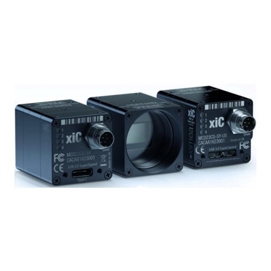
2.3 MP @ 165 fps to 12.4 MP @ 31 fps The XiC camera line comes with several options for interface to the host computer; standard USB (type-C and micro-B) and custom flex line connections. At the time of writing, the USB cameras utilize USB 3.1 gen1 definitions and yield a bandwidth of about 450 Mbyte/s. -
Page 12: Usb3 Vision Camera Applications
Windows 10 (x86 and x64), Windows 7 (x86 and x64), Linux Ubuntu, MacOS 10.8 and newer Software support xiAPI SDK, adapters and drivers for various image processing packages Firmware updates Field firmware updatable table 2-2, common features xiC - Technical Manual Version 1.16... -
Page 13: Model Nomenclature
Resolution in 0.1 MPixel. E.g. 2.3 MPixel Resolution: xxx = 023 y=C: color model y=M: black & white model Global shutter (all XiC cameras are global shutter) Vendor of the sensor zz = SY: Sony [-OPT]: Options OPT = TC: connector Type-C... -
Page 14: Models Overview, Sensor And Models
3.0m USB 3.0 cable, angled micro B USB3 connector CBL-U3-5M0 5.0m USB 3.0 cable, micro B connector on camera side MECH-MC-BRACKET-KIT xiC series tripod mounting bracket with Screws Kit CBL-MQ-FL-0M1 Cable FPC MQ/MC Flex-Line, 0.1m BOB-MQ-FL Break Out Board, Flex-Line, Simple Board Level Micro-B USB3.0 U31PE1G3-V1-X2 PCI express adapter, 2x USB 3.1 ports asmedia ASM1142, xHCI... -
Page 15: Xic Camera Series
3.1. Power Supply The xiC cameras are powered via the USB Micro-B, type C or flexline connector. The input voltage is 5 V DC. The power consumption is 2.2 -3.5W depending on the xiC model. Power supply, via USB system connector: •... - Page 16 Close connector lock figure 3-39, MC FPC insert procedure option -FL xiC - Technical Manual Version 1.16...
- Page 17 Pull cable gently in marked direction. figure 3-40, MC FPC detach procedure option -FL Inserting FPC cables MC option -FV Open connector lock Insert cable Close connector lock. figure 3-41 MC FPC insert procedure option -FV xiC - Technical Manual Version 1.16...
- Page 18 Detaching FPC cable MX X2G2 option –FV Open connector lock Pull gently the cable out as marked. figure 3-42, MC FPC detach procedure option -FV xiC - Technical Manual Version 1.16...
-
Page 19: Power Supply
Digital Input / Output (GPIO) Interface and 3.11 External power supply input (AUX). Power supply, via Digital Input / Output (GPIO) Interface connector: • 5 V (nominal) • 4.45 V to 5.5 V (at the camera connector) 3.2. General Specification 3.2.1. -
Page 20: Lens Mount
3.3. Lens Mount The xiC cameras are compatible with C-mount and CS-mount lenses. C/CS-Mount module B figure 3-1, position C/CS-Mount module B The cameras are delivered with C-mount back focal length. By removing the “C/CS-Mount module B” (see the figure above) the camera can be rebuilt to CS-mount compatibility. -
Page 21: Optical Path
3-4, monochrome camera - filter glass parameter BK7 AR2x - Transmission Curve 350 400 450 500 550 600 650 700 750 800 850 900 950 1000 1050 Wavelength (nm) figure 3-4, monochrome camera - filter glass transmission curve xiC - Technical Manual Version 1.16... -
Page 22: Color Camera Models
3-5, color camera - filter glass parameter ICR650 - Transmission Curve 350 400 450 500 550 600 650 700 750 800 850 900 950 1000 1050 Wavelength (nm) figure 3-5, color camera - filter glass transmission curve xiC - Technical Manual Version 1.16... -
Page 23: Model Specific Characteristics
38.3/37.5/28.3/28.3 (with C/CS Mount module B) 34.1/33.3/24.1/24.1 (without C/CS Mount module B) table 3-6, MC023xG-SY, sensor and camera parameters Notes: Defined for maximal bandwidth. Minimal Exposure and exposure step (Line Period) could be calculated in: Camera performance calculator: https://www.ximea.com/support/attachments/download/7828/Camera_Performance_Calculator.xlsm xiC - Technical Manual Version 1.16... -
Page 24: Quantum Efficiency Curves [%]
3-6, IMX174-mono, quantum efficiency curve, ©SONY 3.5.1.3. Dimensional drawings MC023xG-SY-TC (C-mount [with C/CS mount module B]) USB 3.1 Gen 1 USB3VISION MC023CG-SY-TC power CACAC1623001 USB 3.1 Gen 1 Type C figure 3-7, dimensional drawing MC023xG-SY-TC, C-Mount housing xiC - Technical Manual Version 1.16... -
Page 25: Dimensional Drawings Mc023Xg-Sy-Ub (C-Mount [With C/Cs Mount Module B])
Dimensional drawings MC023xG-SY-UB (C-mount [with C/CS mount module B]) USB 3.1 Gen1 USB3VISION MC023CG-SY-UB power CACAU1623001 Made in SK USB 3.1 Gen 1 For use with XIMEA approved connection cables onl y . figure 3-8, dimensional drawing MC023xG-SY-UB, C-Mount housing xiC - Technical Manual Version 1.16... -
Page 26: Dimensional Drawings Mc023Xg-Sy-Fl (C-Mount [With C/Cs Mount Module B])
3.5.1.5. Dimensional drawings MC023xG-SY-FL (C-mount [with C/CS mount module B]) MC023CG-SY-FL CACAF1623001 USB 3.1 Gen 1 USB3VISION Figure 3-9 dimensional drawing MC023xG-SY-FL, C-Mount housing xiC - Technical Manual Version 1.16... -
Page 27: Dimensional Drawings Mc023Xg-Sy-Fv (C-Mount [With C/Cs Mount Module B])
Note Binning Skipping Not supported Vertical cropping results in increased read speed, horizontal reduces data transfer HW Trigger Trigger with overlap (see 4.3.2.1 Triggered acquisition - ) Not available table 3-8, sensor features available xiC - Technical Manual Version 1.16... -
Page 28: Mc031Xg-Sy
From 1 µs to 14 µs the step is 1µs and the sensor is operating in special mode. This exposure times are not achievable for exposure controlled by trigger pulse length. Saturation level in 8bit digitization is only ¼ of 10bit and 12bit mode (see 4.2.5 Digitization bit depth) xiC - Technical Manual Version 1.16... -
Page 29: Quantum Efficiency Curves [%]
3-10, MC031xG-SY, supported standard readout modes 3.5.2.2. Quantum efficiency curves [%] IMX252- Spectral Response Monochrome Red Bayer Green Bayer Blue Bayer 1000 1050 Wavelength (nm) figure 3-11, IMX252-mono and color, quantum efficiency curves, ©SONY xiC - Technical Manual Version 1.16... -
Page 30: Dimensional Drawings Mc031Xg-Sy-Tc (C-Mount [With C/Cs Mount Module B])
Dimensional drawings MC031xG-SY-UB (C-mount [with C/CS mount module B]) USB 3.1 Gen 1 USB3VISION MC031CG-SY-UB power CECAU1623001 Made in SK USB 3.1 Gen 1 For use with XIMEA approved connection cables onl y . Figure 3-13, dimensional drawing MC031xG-SY-UB, C-mount housing xiC - Technical Manual Version 1.16... -
Page 31: Dimensional Drawings Mc031Xg-Sy-Fl (C-Mount [With C/Cs Mount Module B])
3.5.2.5. Dimensional drawings MC031xG-SY-FL (C-mount [with C/CS mount module B]) MC031CG-SY-FL CECAF1623001 USB 3.1 Gen 1 USB3VISION Figure 3-14, dimensional drawing MC031xG-SY-FL, C-mount housing xiC - Technical Manual Version 1.16... -
Page 32: Dimensional Drawings Mc031Xg-Sy-Fv (C-Mount [With C/Cs Mount Module B])
Skipping Yes, 2x2 Vertical cropping results in increased read speed, horizontal reduces data transfer HW Trigger Trigger with overlap usable (see 4.3.2.1 Triggered acquisition - ) Currently not supported table 3-11, sensor features available xiC - Technical Manual Version 1.16... -
Page 33: Mc050Xg-Sy
From 1 µs to 14 µs the step is 1µs and the sensor is operating in special mode. This exposure times are not achievable for exposure controlled by trigger pulse length. Saturation level in 8bit digitization is only ¼ of 10bit and 12bit mode (see 4.2.5 Digitization bit depth) xiC - Technical Manual Version 1.16... -
Page 34: Quantum Efficiency Curves [%]
3-13, MC050xG-SY, supported standard readout modes 3.5.3.2. Quantum efficiency curves [%] IMX250- Spectral Response Monochrome Red Bayer Green Bayer Blue Bayer 1000 1050 Wavelength (nm) figure 3-16 IMX250 mono and color, quantum efficiency curves, ©SONY xiC - Technical Manual Version 1.16... -
Page 35: Dimensional Drawings Mc050Xg-Sy-Tc (C-Mount [With C/Cs Mount Module B])
Dimensional drawings MC050xG-SY-UB (C-mount [with C/CS mount module B]) USB 3.1 Gen 1 USB3VISION MC050CG-SY-UB power CICAU1623001 Made in SK USB 3.1 Gen 1 For use with XIMEA approved connection cables onl y . figure 3-18, dimensional drawing MC050xG-SY-UB, C-Mount housing xiC - Technical Manual Version 1.16... -
Page 36: Dimensional Drawings Mc050Xg-Sy-Fl (C-Mount [With C/Cs Mount Module B])
3.5.3.5. Dimensional drawings MC050xG-SY-FL (C-mount [with C/CS mount module B]) MC050CG-SY-FL CICAF1623001 USB 3.1 Gen 1 USB3VISION Figure 3-19, dimensional drawing MC050xG-SY-FL, C-Mount housing xiC - Technical Manual Version 1.16... -
Page 37: Dimensional Drawings Mc050Xg-Sy-Fv (C-Mount [With C/Cs Mount Module B])
Yes, 1x2 (H x V) binning supported on monochrome only. Skipping Yes, 2x2 Vertical cropping results in increased read speed, horizontal reduces data transfer HW Trigger Trigger with overlap usable (see 4.3.2.1 Triggered acquisition - ) Not available table 3-14, sensor features available xiC - Technical Manual Version 1.16... -
Page 38: Mc089Xg-Sy
From 1 µs to 14 µs the step is 1µs and the sensor is operating in special mode. This exposure times are not achievable for exposure controlled by trigger pulse length. Saturation level in 8bit digitization is only ¼ of 10bit and 12bit mode (see 4.2.5 Digitization bit depth) xiC - Technical Manual Version 1.16... -
Page 39: Quantum Efficiency Curves [%]
3-16, MC089xG-SY, supported standard readout modes 3.5.4.2. Quantum efficiency curves [%] IMX255- Spectral Response Monochrome Red Bayer Green Bayer Blue Bayer 1000 1050 Wavelength (nm) figure 3-21, IMX255 mono and color, quantum efficiency curve, ©SONY xiC - Technical Manual Version 1.16... -
Page 40: Dimensional Drawings Mc089Xg-Sy-Tc (C-Mount [With C/Cs Mount Module B])
Dimensional drawings MC089xG-SY-UB (C-mount [with C/CS mount module B]) USB 3.1 Gen 1 USB3VISION MC089CG-SY-UB power COCAU1623001 Made in SK USB 3.1 Gen 1 For use with XIMEA approved connection cables onl y . figure 3-23, dimensional drawing MC089xG-SY-UB, C-Mount housing xiC - Technical Manual Version 1.16... -
Page 41: Dimensional Drawings Mc089Xg-Sy-Fl (C-Mount [With C/Cs Mount Module B])
3.5.4.5. Dimensional drawings MC089xG-SY-FL (C-mount [with C/CS mount module B]) MC089CG-SY-FL COCAF1623001 USB 3.1 Gen 1 USB3VISION Figure 3-24, dimensional drawing MC089xG-SY-FL, C-Mount housing xiC - Technical Manual Version 1.16... -
Page 42: Dimensional Drawings Mc089Xg-Sy-Fv (C-Mount [With C/Cs Mount Module B])
Yes, up to 1x2 Vertical cropping results in increased read speed, horizontal reduces data transfer HW Trigger Trigger with overlap usable (see 4.3.2.1 Triggered acquisition - ) Not available table 3-17, sensor features available xiC - Technical Manual Version 1.16... -
Page 43: Mc124Xg-Sy
From 1 µs to 14 µs the step is 1µs and the sensor is operating in special mode. This exposure times are not achievable for exposure controlled by trigger pulse length. Saturation level in 8bit digitization is only ¼ of 10bit and 12bit mode (see 4.2.5 Digitization bit depth) xiC - Technical Manual Version 1.16... -
Page 44: Quantum Efficiency Curves [%]
3-19, MC124xG-SY, supported standard readout modes 3.5.5.2. Quantum efficiency curves [%] IMX253- Spectral Response Monochrome Red Bayer Green Bayer Blue Bayer 1000 1050 Wavelength (nm) figure 3-26, IMX253 mono and color, quantum efficiency curve, ©SONY xiC - Technical Manual Version 1.16... -
Page 45: Dimensional Drawings Mc124Xg-Sy-Tc (C-Mount [With C Mount Module B])
Dimensional drawings MC124xG-SY-UB (C-mount [with C mount module B]) USB 3.1 Gen 1 USB3VISION MC124CG-SY-UB power CUCAU1623001 Made in SK USB 3.1 Gen 1 For use with XIMEA approved connection cables onl y . figure 3-28, dimensional drawing MC124xG-UB, C-Mount housing xiC - Technical Manual Version 1.16... -
Page 46: Dimensional Drawings Mc124Xg-Sy-Fl (C-Mount [With C/Cs Mount Module B])
3.5.5.5. Dimensional drawings MC124xG-SY-FL (C-mount [with C/CS mount module B]) MC124CG-SY-FL CUCAF1623001 USB 3.1 Gen 1 USB3VISION Figure 3-29, dimensional drawing MC124xG-FL, C-Mount housing xiC - Technical Manual Version 1.16... -
Page 47: Dimensional Drawings Mc124Xg-Sy-Fv (C-Mount [With C Mount Module B])
Yes, up to 2x2 Vertical cropping results in increased read speed, horizontal reduces data transfer HW Trigger Trigger with overlap usable (see 4.3.2.1 Triggered acquisition - ) Not available table 3-20, sensor features available xiC - Technical Manual Version 1.16... -
Page 48: User Interface - Leds
~2Hz flash ~2Hz Error flash ~2Hz flash async. table 3-22, LED status during boot Default LED function after xiOpenDevice Color LED function Green Exposure active Blue Frame active Orange table 3-23, LED output description xiC - Technical Manual Version 1.16... -
Page 49: Xic Usb 3.1 Gen1 Type-C Interface
3.7. xiC USB 3.1 Gen1 Type-C Interface Connector Signals Mating Connectors USB 3.1 Standard USB 3.1 Gen1 Type-C Connector Standard USB 3.1 Type C Connector with thumbscrews Screw thread M2, thread distance 15.0mm table 3-24, USB 3.1 mating connector description The USB 3.1 Type C connector is used for data transmission, camera control and power. -
Page 50: Xic Usb 3.1 Gen1 Micro B Interface
CACAU1623001 Made in SK micro B USB 3.1 Gen 1 For use with XIMEA approved connection cables onl y . figure 3-34, position USB 3.1 Gen1 interface 3.8.2. Pinning 1 2 3 4 5 6 7 8 9 10 figure 3-35, pinning USB 3.1 / USB 3.0 connector... -
Page 51: Xic Flex Cable Interface
Trigger/sync digital Output (GPO) - Open collector NPN IN/OUT GND Common pole (IO Ground Trigger/sync digital Input (GPI) Current limited input Ground pins SGND Shield of FPC cable connected to shield of host controller Table 3-29 Pin list for flex cable xiC - Technical Manual Version 1.16... -
Page 52: Inserting / Detaching Fpc Cable
Swapped orientation can cause damage to camera. It is important that the power is turned off when inserting/detaching the cable. figure 3-38, MC FPC cable laser marking Inserting FPC cable MC option -FL Open connector lock Insert cable Close connector lock figure 3-39, MC FPC insert procedure option -FL xiC - Technical Manual Version 1.16... - Page 53 Pull cable gently in marked direction. figure 3-40, MC FPC detach procedure option -FL Inserting FPC cables MC option -FV Open connector lock Insert cable Close connector lock. figure 3-41 MC FPC insert procedure option -FV xiC - Technical Manual Version 1.16...
- Page 54 Detaching FPC cable MX X2G2 option –FV Open connector lock Pull gently the cable out as marked. figure 3-42, MC FPC detach procedure option -FV xiC - Technical Manual Version 1.16...
-
Page 55: Xic Digital Input / Output (Gpio) Interface
Digital Input / Output (GPIO) Interface USB XiC cameras use the 8-pin connector for the GPIO interface and external power supply (AUX) connection and have multiple options for inputs and outputs. The flex line cameras have one input and one output available through the flex line (see pin-out above). -
Page 56: Optically Isolated Digital Input
24.0 On (1) 4 – 6 mA (5mA nominal) table 3-33, digital info, signal levels Note: • Input level Vin represents amplitude of the input signal. • Voltage levels referenced to common ground GND xiC - Technical Manual Version 1.16... -
Page 57: Digital Input - Internal Schematic
G N D ( C omm on I O Gr oun d) figure 3-45, digital input, interface schematic 3.10.3.4. Digital Input – Wiring Power Supply PLC Device Common Camera Input Output GND (Common IO Ground) figure 3-46, digital input, interface wiring xiC - Technical Manual Version 1.16... -
Page 58: Digital Input - Timing
=5V, T =25°C OUTPUT AMBIENT 0.6 µs 43 µs =5V, T =25°C OUTPUT AMBIENT 10mA 0.88 µs 51 µs =11V, T =25°C OUTPUT AMBIENT 25mA 1.4 µs 51 µs =13V, T =25°C OUTPUT AMBIENT xiC - Technical Manual Version 1.16... -
Page 59: Optically Isolated Digital Output - Internal Schematic
Digital output has an open collector switching transistor with common IO Ground. In most cases a power source for external device must be provided. 3.10.4.4.1. Connecting Digital OUTPUT to a NPN-compatible PLC device input (biased) Output state Output switch state Input state Sourcing current Pull up (energized) Relaxing Not energized xiC - Technical Manual Version 1.16... - Page 60 In this case a bidirectional opto-isolated input must be used Power Supply Camera PLC Device DIGITAL OUTPUT GND (Common IO Ground) figure 3-51, Connecting Digital OUTPUT to a NPN-compatible PLC device - single input xiC - Technical Manual Version 1.16...
- Page 61 Pull up resistor can be calculated as follows: input Where: power supply voltage. Must be higher than required input amplitude required input amplitude input driving current (corresponding to input amplitude) input Remember to use the appropriate resistor power rating xiC - Technical Manual Version 1.16...
- Page 62 Low power Red 1.7V 2.0V Orange 2.0V 2.1V Yellow 2.1V 2.2V Green 1.9V 2.5V Emerald Green 2.1V 2.7V Blue 2.5V 3.7V White 2.8V 3.8V Infra-Red 1.3V 1.8V Opto coupler table 3-36, digital output, LED driving xiC - Technical Manual Version 1.16...
- Page 63 3-54, Inductive load (Relay) Driving (inverted logic) For positive logic you can use a second bipolar transistor. Power Supply Camera DIGITAL OUTPUT GND (Common IO Ground) figure 3-55, Inductive load (Relay) Driving (non-inverted logic) xiC - Technical Manual Version 1.16...
-
Page 64: Digital Output - Timing
Output delay depending on output current: Output current OFF->ON ON->OFF 0.55μs 184μs 0.55μs 182μs 10mA 0.55μs 133μs 25mA 0.55μs 113μs table 3-39, digital output, current depending timing Note: Measured at conditions: V =11V, T =25°C OUTPUT AMBIENT xiC - Technical Manual Version 1.16... -
Page 65: Non-Isolated Digital Lines (-Ub And -Tc Only)
External power supply input (AUX) Item Parameter/note Supported voltage range 4.5-5.5V Typical input current* 0.65A, @5V while acquiring Maximum input current* 0.67A, @5V Protection Over/under voltage protection * Is model depended. Used values are for MC124MG-SY-TC xiC - Technical Manual Version 1.16... -
Page 66: Heat Dissipation
Heat Dissipation XIMEA strives to offer the smallest cameras with the highest performance. Although the cameras are first in terms of power efficiency, the high packing density of components can lead to elevated temperatures, and an adequate dissipation of this heat must be ensured. -
Page 67: Cbl-U3-1M0 / Cbl-U3-3M0 / Cbl-U3-5M0
USB 3.0 signal Ground MicB_SSRX- USB 3.0 SuperSpeed receiver signal pair MicB_SSRX+ table 3-42, USB3 connector, pin assignment x x .x M X Y Z Specified Week Cable Length Year figure 3-59, label details USB3 cable xiC - Technical Manual Version 1.16... -
Page 68: Cbl-U3-3M0-Ang
USB 3.0 signal Ground MicB_SSRX- USB 3.0 SuperSpeed receiver signal pair MicB_SSRX+ table 3-44, USB3 connector, pin assignment x x .x M X Y Z Specified Week Cable Length Year figure 3-62, label details USB3 cable angled xiC - Technical Manual Version 1.16... -
Page 69: Cbl-Mq-Fl-0M1
3.15. CBL-MQ-FL-0M1 Cable FPC MQ Flex-Line, 0.1m can be used for connecting xiC flex line models to carrier board or trough adapter and standard USB 3.0 cable to the host computer. figure 3-63, flex cable It is necessary to observe cable orientation as the wiring is nor symmetrical. The cables end are marked with: “CAM”... -
Page 70: Cbl-702-8P-Sync-5M0
3.17. CBL-702-8P-SYNC-5M0 5.0m xiC / xiT series I/O Sync cable 8 poles Sync cable wiring figure 3-66, IO/AUX cable pin numbering color Signal White AUX power supply input Brown INOUT2 - non-isolated Input/Output Green OUT1 - Opto-isolated Output Yellow OUT_GND Opto-Isolated output ground pole... -
Page 71: Tripod Adapter - Mech-Mc-Bracket-Kit
Tripod Adapter – MECH-MC-BRACKET-KIT xiC series tripod mounting bracket figure 3-67, mounting tripod adapter xiC series tripod mounting bracket with 1/4-20 thread. Use 4x SROB-M2x4-CUST screws (included) for mounting. Bracket can be mounted on the bottom or top side of the camera. 3.18.1. -
Page 72: Usb 3 Host Adapters
USB 3.0 to PCI Express x1 Gen2 Host Card figure 3-69, USB3 host adapters https://www.ximea.com/support/projects/usb3/wiki/USB_3_Host_Adapters Please refer to following page for more information. System requirements All requirements depend on selected host adapter. Please refer to host adapter specification xiC - Technical Manual Version 1.16... -
Page 73: Operation
Operation For a proper operation of your xiC camera there are certain requirements that have to be met. You can read more about these requirement as well as about the correct usage of xiC camera in the following sections. 4.1. -
Page 74: Usb 3.1 Host Adapter
Cables The USB 3.1 Gen1 cable that you use with the xiC camera is responsible for the power supply and the data transfer to the PC. It is required to use an industrial USB 3.1 Gen1 cable with a proper wiring and shielding. We recommend using XIMEA industrial USB 3.1 Gen1 cables in order to achieve the maximum possible performance of the camera. -
Page 75: Video Formats
ROI, also called area-of-interest (AOI) or windowing, allows the user to specify a sub-area of the original sensor size for read- out. Depending on the sensor xiC cameras support the definition of one single ROI by specifying the size (width and height) as well as the position (based on upper left corner) of the of the sub-area. -
Page 76: Image Data Output Formats
4.2.4. Image Data Output Formats All modes are provided by the xiAPI or standard interfaces using the xiAPI (please note 5.1 Accessing the Camera). Each xiC cameras supports several Image Data Output Formats. Mode Description RAW8 Raw sensor data, 8 Bit per pixel, single channel... -
Page 77: Digitization Bit Depth
10bit mode using only ¼ of the saturation. This lead to four times brighter images compared to 10bit and 12bit modes. figure 4-2, Saturation vs Sensor output for different digitization bit depths 2 generation IMX sensors xiC - Technical Manual Version 1.16... -
Page 78: Acquisition Modes
In this mode the timing depends on the Exposure Time and Data Readout Time. All xiC cameras support limiting of FPS. When set the camera will limit the frame rate so it does not exceed the set value. Frame_Rate_Control: https://www.ximea.com/support/wiki/allprod/Frame_Rate_Control Please see: This is also applicable in case of triggered acquisition. -
Page 79: Triggered Acquisition - Single Frame
) the following applies. The next trigger after one is processed needs to be applied so the end of tper the triggered exposure does not overlap with the readout of the previous frame. �� > max ( �� , �� ) + �� �������� ���� ������ ������ xiC - Technical Manual Version 1.16... -
Page 80: Triggered Acquisition - Burst Of Frames
Also it can be used to trigger several images in sequence with different exposure time. Exposure time is measured and reported in image metadata. figure 4-7, Exposure defined by trigger pulse length Exposure Defined by Trigger Pulse Length: Please see: https://www.ximea.com/support/wiki/allprod/Exposure_Defined_by_Trigger_Pulse_Length xiC - Technical Manual Version 1.16... -
Page 81: Multiple Exposures In One Frame
Multiple exposures in one frame All Sony IMX based xiC models except MC023xG-SY support defined number of exposures exposed into a single frame. In this mode the number of exposures need to be defined. The number of exposures can be defined using the XiApi parameter XI_PRM_EXPOSURE_BURST_COUNT. -
Page 82: Camera Parameters And Features
4.5.4. Sharpness Only for color models: As a part of the color filtering process, it is possible to adjust the sharpness of the image. xiC - Technical Manual Version 1.16... -
Page 83: Color Correction Matrix
This list is then used for the correction of acquired images during operation. The correction is inactive by default, but can be turned on by the user if a non-processed output is required. xiC - Technical Manual Version 1.16... -
Page 84: Software
5.1.1. Proprietary API All XIMEA cameras are supported by the same unified APIs (application programming interface). The API is a software interface between the camera system driver and the application. Different APIs are available for different programming environments, e.g. xiAPI (see 5.7.1 XIMEA APIs) for C/C++ developments and xiAPI.Net for C#/.Net based developments 5.1.2. -
Page 85: Ximea Camtool
5.2. XIMEA CamTool The CamTool is a cross-platform application showcasing the features of all XIMEA camera families. Short description It runs on Windows, Linux, macOS systems offering a substantial imaging tool set, which can be further extended with custom modules using a plugin infrastructure. CamTool is based on Qt for the UI and xiAPI for the camera control. Its camera settings... - Page 86 Functions to see live image from multiple XIMEA cameras connected control the camera parameters store of camera image and video analyze the image properties histogram and line profile image averaging, image flip/mirror software trigger timer, save/load camera and program settings ...
-
Page 87: Supported Vision Libraries
Libraries maintained by XIMEA All cameras listed in the section Products are supported with these libraries. XIMEA commits to update the API within twelve months after a new major release. XIMEA warranties backwards compatibility of these software packages for two major releases. -
Page 88: Ximea Windows Software Package
5.4.1. Contents The package contains: • OS Drivers of all XIMEA camera types for OS Microsoft Windows XP SP3 32bit, Windows 7 32/64 bit, Windows 8 32/64 bit, Windows Server 2008 R2 x86-64, Windows 10 32/64 bit. xiAPI xiAPI.NET xiApiPython •... - Page 89 Select the Software components you want to install. You can uncheck the components you don't want to install, but it is recommended to leave them all checked. figure 5-3, XIMEA Windows Software Package installation - 2 • Specify the install location - you can leave the default location or change it to your desired location.
- Page 90 • Now the XIMEA API Software Package should start copying files, updating System Variables and installing drivers if necessary. figure 5-5, xiAPI installation, Windows - 4 • Installation is completed. figure 5-6, xiAPI installation, Windows - 5 • Finish. xiC - Technical Manual Version 1.16...
-
Page 91: Ximea Linux Software Package
5.5. XIMEA Linux Software Package XIMEA Linux Software Package is tarred installer with files that can be run on Linux Ubuntu 14.04 and 16.04 (32 and 64 Bit) and newer releases. 5.5.1. Contents The package contains: • Driver (beta version) for XIMEA USB2 and USB3 cameras •... - Page 92 5-8, XIMEA Linux Software Package installation - 2 Note: If logged in user is not root, you will be asked for your password to get root access, because the installation runs with root account using sudo. xiC - Technical Manual Version 1.16...
-
Page 93: Ximea Macos Software Package
5.6. XIMEA macOS Software Package XIMEA macOS Software Package is native DMG installer that can be run on macOS 10.8 (Mountain Lion) or newer. 5.6.1. Contents The package contains: • Driver (beta version) for XIMEA USB2 and USB3 cameras •... -
Page 94: Start Ximea Camtool
A window with package contents will open. 5.6.3. Start XIMEA CamTool • Connect camera • Start Applications / XIMEA CamTool • Start acquisition by clicking on orange triangle at upper left corner of CamTool xiC - Technical Manual Version 1.16... -
Page 95: Programming
• – Integrated API into PYTHON. 5.7.2. xiAPI Overview xiAPI stands for XIMEA Application Programming Interface. It is a common interface for all XIMEA cameras. Architecture API is a software interface between the camera system driver and application. • On Windows: xiAPI is compiled into xiapi32.dll or xiapi64.dll •... -
Page 96: Xiapi Parameters Description
For a complete list of available parameter, please visit the xiAPI online manual at http://www.ximea.com/support/wiki/apis/XiAPI_Manual Note: Since xiAPI is a unified programming interface for all of XIMEA‘s cameras, not all of the described parameters apply for every camera and sensor model. -
Page 97: Acquire Images
XI_PRM_GPI_MODE, XI_GPI_TRIGGER) // set digital output 1 mode xiSetParamInt(xiH, XI_PRM_GPO_SELECTOR, 1); xiSetParamInt(xiH, XI_PRM_GPO_MODE, XI_GPO_EXPOSURE_ACTIVE); xiStartAcquisition(handle1); // Trigger signal should start image exposure within timeout #define TIMEOUT_IMAGE_WAITING_MS 10000 xiGetImage(handle, TIMEOUT_IMAGE_WAITING_MS, &image); // process image here… xiC - Technical Manual Version 1.16... -
Page 98: Xiapi Auto Bandwidth Calculation
For more information on programing according the USB3 VISION standard, please visit the standard’s website at http://www.visiononline.org/vision-standards-details.cfm?type=11 5.7.8. GenICam For more information on programing according the GenICam standard, please visit the standard’s website at http://www.emva.org/standards-technology/genicam/ xiC - Technical Manual Version 1.16... -
Page 99: Ximea Control Panel
5.8. XIMEA Control Panel The XIMEA Control Panel (xiCOP), is a diagnostics and management tool for all XIMEA cameras. xiCOP is currently only available for Windows operating system. figure 5-12, xiCOP Features • Facilitates diagnostics of system performance bottlenecks. xiCOP is capable of retrieving the system’s hardware tree, thus problematic hardware configurations can be identified. -
Page 100: Appendix
Please make sure, that you have connected your xiC camera with the XIMEA USB 3.0 cable to an appropriate USB 2.0 or USB 3.0 port. Ensure that the connections are carefully locked. Follow the instructions described in chapter 5.2 XIMEA CamTool (run the xiC camera with the Ximea CamTool). -
Page 101: What Is The Real Transfer Speed
What voltage should be applied to Digital Input of xiC to turn it on/off? xiC camera features two type of inputs (-UB, -TC only). First is optoisolated input only. Second is INOUT set to input function. Following table shows different levels of Voltage on Digital Input (VDI) on xiC and their logical interpretation. -
Page 102: Product Service Request (Psr)
Step 5 - Waiting for Service Conclusion Once we have received the camera, we will send you a notification. The XIMEA Service will then check the status of the camera that you have sent for a possible repair. Depending on warranty conditions, product status and agreement one of the following... -
Page 103: Safety Instructions And Precautions
Power supply xiC camera can be bus powered or powered from external power supply (-UB and –TC models only). The flex line models (-FL, - FV) could be powered only via the flex cable. For more information see 3.1 Power Supply 6.3.5. -
Page 104: Protect The Optical Components
XIMEA warrants to the Original Purchaser that the Camera provided is guaranteed to be free from material and manufacturing defects for a period of two years. Should a unit fail during this period, XIMEA will, at its option, repair or replace the damaged unit. -
Page 105: Disclaimer Of Warranty
XIMEA does not assume any liability for damage that is the result of improper use of its products or failure to comply with the operating manuals or the applicable rules and regulations. - Page 106 Purchaser are fulfilled. If these conditions are not fulfilled in time, times set shall be extended reasonably; this shall not apply if the Supplier is responsible for the delay. 2. If non-observance of the times set is due to: xiC - Technical Manual Version 1.16...
- Page 107 2. Before the erection work starts, the Purchaser shall unsolicitedly make available any information required concerning the location of concealed electric power, gas and water lines or of similar installations as well as the necessary structural data. xiC - Technical Manual Version 1.16...
- Page 108 9. The Purchaser's right of recourse against the Supplier pursuant to Sec. 478 BGB is limited to cases where the Purchaser has not concluded an agreement with its customers exceeding the scope of the statutory provisions governing claims based on xiC - Technical Manual Version 1.16...
- Page 109 To the extent this is not justifiable for economic reasons, the Supplier shall have the right to rescind the contract. The same applies if required export permits are not granted or cannot be used. If the Supplier intends to xiC - Technical Manual Version 1.16...
-
Page 110: Copyright
Added chapter 3.12 Heat dissipation, added LED status after xiOpenDevice 1.14 10/19/2017 Added connector description for –FL and –FV variants 1.15 01/17/2018 Corrected exposure time ranges, updated optical path paragraph 1.16 08/24/2018 Added 8bit digitization mode description, FPC insertion guide line xiC - Technical Manual Version 1.16... -
Page 111: Glossary
Red Green Blue Region of interest Saturation value Software Development Kit SIMR Single integration multiple ROI Signal To Noise (ratio) Serial peripheral interface Software To be determined – some parameters require characterization Integration time xiC - Technical Manual Version 1.16... -
Page 112: List Of Figures
3-38, MC FPC cable laser marking figure 3-39, MC FPC insert procedure option -FL figure 3-40, MC FPC detach procedure option -FL figure 3-41 MC FPC insert procedure option -FV figure 3-42, MC FPC detach procedure option -FV xiC - Technical Manual Version 1.16... - Page 113 4-9, Multiple exposures - exposure time defined by trigger pulse length, number of exposures set to 5 figure 5-1, CamTool Layout figure 5-2, XIMEA Windows Software Package installation - 1 figure 5-3, XIMEA Windows Software Package installation - 2...
- Page 114 5-9, XIMEA macOS Software Package installation - 1 figure 5-10, xiAPI installation, MacOS - 2 figure 5-11, GPIO - schematic figure 5-12, xiCOP xiC - Technical Manual Version 1.16...
-
Page 115: List Of Tables
3-33, digital info, signal levels table 3-34, digital input, timing table 3-35, Optically isolated digital output, general info table 3-36, digital output, LED driving table 3-37, digital output, wiring examples table 3-38, digital output, typical timing xiC - Technical Manual Version 1.16... - Page 116 6-1, use xiCOP before contacting technical support table 6-2, interface depending transfer rates table 6-3, voltage levels for optoisolated digital input table 6-4, voltage levels for non-isolated digital input table 6-5, service operations overview xiC - Technical Manual Version 1.16...
- Page 117 XIMEA GmbH Am Mittelhafen 16 • 48155 Münster • Germany • www.ximea.com © Copyright 2017, XIMEA GmbH, All rights reserved...
Need help?
Do you have a question about the xiC and is the answer not in the manual?
Questions and answers