Advertisement
Quick Links
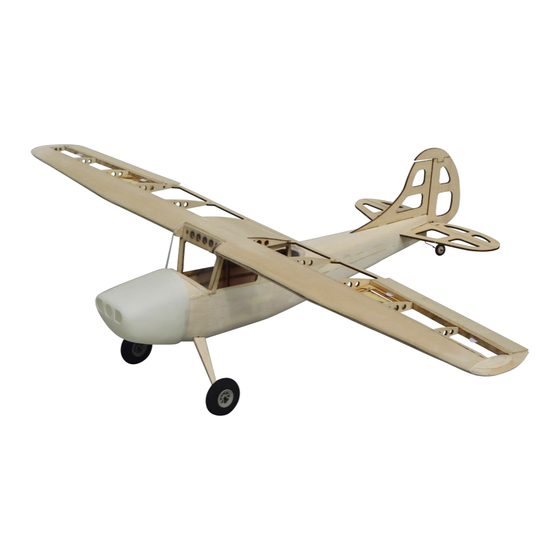
Cessna L-19 Bird Dog
Building Instructions
Specifications
Wing Span
749,3 mm / 29.5 in
Wing Area
7,15 sq dm / 0.769 sq ft
Flying weight
150 g - 180 g / 5.29 - 6.34 oz.
Fuselage length
500 mm / 19.68 in
Scale
1 / 15
Requires
RC transmitter with at least 4 channels
Aileron: 2,5 g servos(ES9251) x 2
Rudder & Elevator: 2,5 g servos(ES9251) x 2
Motor system: EPS1404 7800KV
1
©Sebastian Hansen
Advertisement

Related Manuals for Tony Ray's AeroModel Cessna L-19 Bird Dog


Summary of Contents for Tony Ray's AeroModel Cessna L-19 Bird Dog
- Page 1 Cessna L-19 Bird Dog Building Instructions Specifications Wing Span 749,3 mm / 29.5 in Wing Area 7,15 sq dm / 0.769 sq ft Flying weight 150 g - 180 g / 5.29 - 6.34 oz. Fuselage length 500 mm / 19.68 in...
- Page 2 ©Sebastian Hansen...
-
Page 3: Before You Begin
BEFORE YOU BEGIN Attentions and Tips 1. Read through the manual before you begin, thus you will have an overall idea of what to do. 2. Check all parts in the scope of delivery list. If you find any serious defects or missing parts, please contact Tony and Sebastian directly. - Page 4 KIT INVENTORY Sheet Wood Inventory Item Quantity 2,0 mm Plywood 2,0 mm Balsa 1,0 mm Balsa 1,0 mm Plywood Hardware 1.Hardware in plastic bag Laser cut PVC sheet Paper hinge PU wheels Steel rod (diameter: 1,5 mm) 25 cm Steel rod (diameter: 0,8 mm) 10 cm Carbon rod (diameter: 1 mm) M2 Four Claws Nut...
- Page 5 ASSEMBLY-Fuselage Step2 Step 1: 1,5 mm Steel rod (bend according to the plan Step 3 Step 4 Step 5 Step 6 ©Sebastian Hansen...
- Page 6 Step 7 Step 8 Step 9 Step 10 Step 11: 2 x 2 mm Balsa strips Step 12 Step 13 Step 14 ©Sebastian Hansen...
- Page 7 Step 15 Step 16 Step 17 Step 18 Step 19 Step 20: Using 1,5 x 1,5 mm Balsa strips fill the gap Step 21 Step 22 ©Sebastian Hansen...
- Page 8 Step 23 Step 24 Step 25 Step 26 Step 27 Step 28 Step 29 Step 30 ©Sebastian Hansen...
- Page 9 Step 31 Step 32 Step 33: Sand the fuselage Step 34 Step 35 Step 36 Step 37 Step 38 ©Sebastian Hansen...
- Page 10 ASSEMBLY-Wing Step 1 Step 2 Step 3 Step 4 Step 5: 2 x 2 mm Balsa strips Step 6 ©Sebastian Hansen...
- Page 11 Step 7 Step 8 Step 9: Sand the back edge to a bevel Step 10 Step 11 Step 12 Step 13 Step 14: Sand the wing tips carefully ©Sebastian Hansen...
- Page 12 Step 15 Step 16 Step 17 Step 18: Sand the edge Step 19 Step 20 Step 21 Step 22 ©Sebastian Hansen...
- Page 13 ASSEMBLY-Electronics Step 1: Step 2 Aileron Servo ES9251. Attention Install servo before cover the wing Step 3 Step 4: Install the servo to WC7 Step 5: Bend the pin Step 6: Carbon rod (diameter: 1 mm length: 25 mm) Bent pin. Heat shrinkable tube. ©Sebastian Hansen...
- Page 14 Step 7 Step 8: Connect the left and right elevators with a staple Step 9: Drill holes in the position shown Step 10: Carbon rod. Pin. Heat shrinkable tube Step 11: Elevator and Rudder Servo: ES9251 Step 12 Step 13 Step 14 ©Sebastian Hansen...
- Page 15 Step 15: Using Epoxy glue Step 16: Install Brushless Motor System. M1.7 x 6 Screws. M3 x 10 Screw Step 17: M2 x 8 Screws Step 18: Install Propeller. M1.7 x 6 Screws. The propeller shaft hole diameter needs to be enlarged to 4 mm. Step 19: Step 20: Drill holes according to the position of M5 hole...
- Page 16 1. CG: 30 mm from the leading edge 2.Control Travel ELEVATOR ±15° RUDDER ±15° AILERON ±20° Thank you! ©Sebastian Hansen...
Need help?
Do you have a question about the Cessna L-19 Bird Dog and is the answer not in the manual?
Questions and answers