Table of Contents
Advertisement
Quick Links
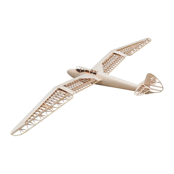
Minimoa Mo2a
1/6
Build Instructions
Specifications
Wing Span
112 in / 2844.8 mm
Wing Area
54.8 sq dm
Flying Weight
1.8 kg - 1.9 kg
Fuselage Length
1218 mm
Scale
1 / 6
Requires
RC Transmitter with at least 7 Channels
Airbrake: 9 g Servo (ES08/DS395) x 2
Flaps: 9 g Servo (ES08/DS395) x 2
Aileron: 17 g Servo (ES3004/AS82MG) x 2
Rudder & Elevator: 17 g Servo (ES3004/AS82MG) x 2
1
© Sebastian Hansen
Advertisement
Table of Contents

Subscribe to Our Youtube Channel
Related Manuals for Tony Ray's AeroModel Minimoa Mo2a


Summary of Contents for Tony Ray's AeroModel Minimoa Mo2a
- Page 1 Minimoa Mo2a Build Instructions Specifications Wing Span 112 in / 2844.8 mm Wing Area 54.8 sq dm Flying Weight 1.8 kg - 1.9 kg Fuselage Length 1218 mm Scale 1 / 6 Requires RC Transmitter with at least 7 Channels...
-
Page 2: Table Of Contents
INDEX BEFORE YOU BEGIN ------------------------------------------------------------------------------------------P.3 KIT INVENTORY -------------------------------------------------------------------------------------------P.4-P.5 ASSEMBLY-Fuselage I -----------------------------------------------------------------------------------P6-P.10 ASSEMBLY-Fuselage II --------------------------------------------------------------------------------P.11-P.19 ASSEMBLY-Canopy ------------------------------------------------------------------------------------P.20-P.21 ASSEMBLY-Vertical & Horizontal Tail -------------------------------------------------------------P.22-P.26 ASSEMBLY-Centre Wing Section -------------------------------------------------------------------P.27-P.30 ASSEMBLY-Outer Wing Section --------------------------------------------------------------------P.31-P.34 ASSEMBLY-Wing Covering ---------------------------------------------------------------------------P.35-P.37 ASSEMBLY-Seats and Details -----------------------------------------------------------------------P.38-P.40 ASSEMBLY-Electronics --------------------------------------------------------------------------------P.40-P.45 © Sebastian Hansen... -
Page 3: Before You Begin
BEFORE YOU BEGIN Tips and Tricks 1. Read through the manual before you begin, thus you will have an overall idea of what to do. 2. Check all parts in the scope of delivery list. If you find any serious defects or missing parts, please contact Tony and Sebastian directly. -
Page 4: Kit Inventory
KIT INVENTORY Sheet Wood Inventory Item Mark Quantity 1.5 mm Balsa A Series: A1 - A26 1.5 mm Paulownia A Series: A27 - A28 1.5 mm Plywood A Series: A29 2.0 mm Balsa B Series: B1 - B10 2.0 mm Paulownia B Series: B11 - B12 2.0 mm Plywood B Series: B13 - B20... - Page 5 M2 Screw Nut M2 x 10 Screws M2 x 8 Screws (Spacer Version) Copper hinge M1 x 3 Screws 4.Aluminum parts Aluminum Tube (Outer Diameter: 10 mm, Inner Diameter: 6 mm) 5.Vacuum Formed Canopy Canopy Paper Parts 1:1 Drawing © Sebastian Hansen...
-
Page 6: Assembly-Fuselage I
ASSEMBLY-Fuselage I Step 1 Step 2 Step 3 Step 4 Step 5 Step 6 © Sebastian Hansen... - Page 7 Step 7 Step 8 Step 9 Step 10 Step 11 Step 12 Step 13 Step 14 © Sebastian Hansen...
- Page 8 Step 15 Step 16: Sand the edge Step 17 Step 18 Step 19 Step 20 Step 21 Step 22 © Sebastian Hansen...
- Page 9 Step 23 Step 24 Step 25: M3 Four Claws Nut Step 26 Step 27 Step 28 Step 29 Step 30: 2 x 8 mm Paulownia Strips (located in B12) © Sebastian Hansen...
- Page 10 Step 31: 2 x 8 mm strips Step 32 Step 33: 3 x 3 mm Balsa strips Step 34 Step 35 Step 36 Step 37: Step 38 Install PVC Tube before cover the fuselage (Outer Diameter: 3 mm, Inner Diameter: 2 mm) Before cove r the fuselage, you need reinforce the ce ntral wing box, wrap it with glass fiber cloth, bind it with Kevlar wire or carbon fiber wire , and paint it with epoxy resin to cure.
-
Page 11: Assembly-Fuselage Ii
ASSEMBLY-Fuselage II Step 1 Step 2 Step 3: Step 4 Attention to the texture of FC1 and FC2 Step 5 Step 6 © Sebastian Hansen... - Page 12 Step 7 Step 8 Step 9 Step 10: Sand the edges Step 11 Step 12: Sand the edge Step 13: Step 14 For some quadrilate ral fuselage covering parts, it is not easy to dis tinguis h the direction. If we have a dot on a corner of a pa rt, it means that the corner is: top & front. ©...
- Page 13 Step 15 Step 16 Step 17 Step 18 Step 19 Step 20 Step 21 Step 22 © Sebastian Hansen...
- Page 14 Step 23 Step 24 Step 25 Step 26: Sand the edge Step 27 Step 28 Step 29: Sand the edge Step 30 © Sebastian Hansen...
- Page 15 Step 31 Step 32 Step 33 Step 34 Step 35 Step 36 Step 37 Step 38 © Sebastian Hansen...
- Page 16 Step 39: Step 40 Sand the bottom edge to a bevel (inner side) Step 41 Step 42 Step 43 Step 44 Step 45 Step 46 © Sebastian Hansen...
- Page 17 Step 47 Step 48 Step 49 Step 50 Step 51 Step 52 : Sand the edge to a bevel (inner side) Step 53 Step 54 © Sebastian Hansen...
- Page 18 Step 55 Step 56 Step 57: Step 58 6 x 6 mm Balsa strips. 1.5 mm Balsa, width: 17 mm located in A7 Step 59 Step 60 Step 61: Step 62 Sand the edge to a bevel. Bevel width: 5 mm ©...
- Page 19 Step 63: Sand the front edge Step 64 Step 65 Step 66 My Notes: Step 67 © Sebastian Hansen...
-
Page 20: Assembly-Canopy
ASSEMBLY-Canopy Step 1 Step 2 Step 3 Step 4: Sand the edge Step 5: 2 x 2 mm Balsa strips Step 6 © Sebastian Hansen... - Page 21 Step 7 Step 8 Step 9 Step 10: If gaps exist, fill them with scraps. Align this edge first Step 11: Sand the edge Step 12 My Notes: Step 13: 0.5 mm PVC sheet. Please do not CA glue in this step ©...
-
Page 22: Assembly-Vertical & Horizontal Tail
ASSEMBLY-Vertical & Horizontal Tail Step 1 Step 2 Step 3 Step 4 Step 5 Step 6: A gap of 2 mm © Sebastian Hansen... - Page 23 Step 7 Step 8 Step 9 Step 10 Step 11 Step 12 Step 13 Step 14 © Sebastian Hansen...
- Page 24 Step 15 Step 16 Step 17: Polish the edges Step 18 Step 19 Step 20 Step 21 Step 22 © Sebastian Hansen...
- Page 25 Step 23 Step 24 Step 25: Polish the edges Step 26 Step 27 Step 28 Step 29 Step 30: Polish the edges © Sebastian Hansen...
- Page 26 Step 31: Smooth this place Step 32 My Notes: © Sebastian Hansen...
-
Page 27: Assembly-Centre Wing Section
ASSEMBLY-Center Wing Section Step 1: 2 x 8 mm Pine strips Step 2 Step 3: Step 4 Mark of ribs. Sand this edge to a bevel. Bevel width: 5 mm Step 5 Step 6: 3 x 3 mm pine strips. Do not install front PVC Tube in this step! PVC tube (back) ©... - Page 28 Step 7: Step 8: Install R1.5 - R4.5 and front PVC Tube Note the orientation of part W3, it is asymmetrical and marked “outer side” towards the outer wing Step 9: Install R5.5 – R13.5 Step 10 Step 11 Step 12 Step 13 Step 14: Remove the flap ©...
- Page 29 Step 15: Sand these edges Step 16 Step 17: Sand this edge to a bevel Step 18 Step 19: Clean up the air brake cabin Step 20 Step 21 Step 22: Please pay attention to distinguish these parts, they look similar but cannot be used universally ©...
- Page 30 Step 23: Step 24 Please assemble the brake pa ds strictly according to the combination and position shown in the picture, otherwise they cannot be pe rfectly re tracted into the Cabin. Step 25: Step 26 The combination “BR 4,5,6” is placed on top. Combination “BR 1,2,3” is placed at the bottom. Steel Push rod Diameter: 1.2 mm, Length: 170 mm My Notes: ©...
-
Page 31: Assembly-Outer Wing Section
ASSEMBLY-Outer Wing Section Step 1 Step 2: There is a 2 mm gap between W11 and the mounting surface. When installing, put 2 mm thick wood chips under W11 temporarily. Step 3: 6 x 6 mm Balsa strips Step 4 Step 5 Step 6: 2 x 8 mm pine strips ©... - Page 32 Step 7 Step 8 Step 9: 3 mm pine in C5 Step 10 Step 11: Fill this space and using epoxy glue Step 12 Step 13 Step 14 Sand the edge to a bevel, bevel width: 5 mm © Sebastian Hansen...
- Page 33 Step 15 Step 16: Install the top 2 x 8 mm pine strips Step 17 Step 18 Step 19 Step 20 Step 21 Step 22 © Sebastian Hansen...
- Page 34 Step 23: Install R16.5 - R32.5 Step24 Step 25 Step 26: Install A1 - A26 Step 27 Step 28: Sand the edge Step 29 Step 30 © Sebastian Hansen...
-
Page 35: Assembly-Wing Covering
ASSEMBLY-Wing Covering Step 1 Step 2 Step 3 Step 4 Step 5 Step 6: Sand the front edge to a bevel © Sebastian Hansen... - Page 36 Step 7 Step 8 Step 9 Step 10 Step 11 Step 12 Step 13 Step 14 © Sebastian Hansen...
- Page 37 Step 15 Step 16: 2 x 5 mm Balsa strips Step 17 Step 18: My Notes: © Sebastian Hansen...
-
Page 38: Assembly-Seats And Details
ASSEMBLY-Seats and Details Step 1: 1.5 mm Balsa Step 2 Step 3 Step 4 Step 5 Step 6 © Sebastian Hansen... - Page 39 Step 7 Step 8 Step 9 Step 10: M3 x 1 Magnets Step 11 Step 12 Step 13 Step 14 © Sebastian Hansen...
- Page 40 Step 15 Step 16 Step 17 Step 18 Step 19 Step 20 My Notes: © Sebastian Hansen...
-
Page 41: Assembly-Electronics
ASSEMBLY-Electronics (Reference example is motored version) Step 1: Step 2 M2 Steel push rod, Bend it 20 - 25 degrees at the end Step 3: Step 4: Drill an additional 1.5 mm hole near the top. M2 Nylon rocker head Reinforce here with epoxy resin, fiberglass cloth, and wrap Kevlar or carbon fiber filaments Step 5: Step 6: Plastic collet... - Page 42 Step 7 Step 8: Motor: Designed for DULSKY 3548EGL Also suitable for TORQUE LS 3223/10, Xpower XC3223/10 LS, HACKER A3012XL Step 9 Step 10 Step 11: Step 12: Flaps: 9 g servo (ES08/DS395) Steel push rod (Diameter 1.2 mm) Bend it according to the drawing. Plastic collet Step 13: Step 14: Aileron: 17 g Servo (ES3004/AS82MG)
- Page 43 Step 15 Step 16: Drill holes and install a screw to connect the fuselage and wings My Notes: © Sebastian Hansen...
- Page 44 BEFORE YOU FLY 1. CG (center of gravity): 2. Horizontal stabilizer mounting angle: © Sebastian Hansen...
- Page 45 3. Control Travel ELEVATOR ±15° RUDDER ±15° AILERON +30°- 10° Thank you! © Sebastian Hansen...
Need help?
Do you have a question about the Minimoa Mo2a and is the answer not in the manual?
Questions and answers