Advertisement
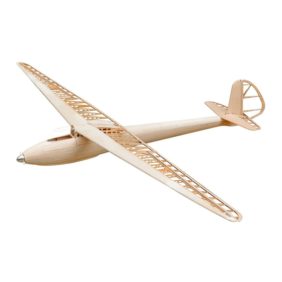
Weihe50
Wingspan
Wing Area
Flying weight
Fuselage length
Scale
RC transmitter with at least 4 channels
Tail: 9g servos (ES08/DS395) x 2
Aileron: 9mm Thin servos (ES3301/ES3302) x 2
©Sebastian Hansen
Building Instructions
Specifications
Requires
109 in / 2770mm
51.24 sq dm
1.2kg-1.4kg
1241mm
1 / 6.5
1
Advertisement
Table of Contents

Subscribe to Our Youtube Channel
Related Manuals for Tony Ray's AeroModel Weihe50


Summary of Contents for Tony Ray's AeroModel Weihe50
- Page 1 Weihe50 Building Instructions Specifications Wingspan 109 in / 2770mm Wing Area 51.24 sq dm Flying weight 1.2kg-1.4kg Fuselage length 1241mm Scale 1 / 6.5 Requires RC transmitter with at least 4 channels Tail: 9g servos (ES08/DS395) x 2 Aileron: 9mm Thin servos (ES3301/ES3302) x 2...
- Page 2 INDEX BEFORE YOU BEGIN -------------------------------------------------------------------------------------------P.3 KIT INVENTORY -------------------------------------------------------------------------------------------P.4-P.5 ASSEMBLY-Vertical Tail ---------------------------------------------------------------------------------P.6-P.8 ASSEMBLY-Horizontal Tail -----------------------------------------------------------------------------P.9-P.11 ASSEMBLY-Fuselage I ---------------------------------------------------------------------------------P.12-P.16 ASSEMBLY-Fuselage II --------------------------------------------------------------------------------P.17-P.19 ASSEMBLY-Canopy ------------------------------------------------------------------------------------P.20-P.21 ASSEMBLY-The Wing ---------------------------------------------------------------------------------P.22-P.27 ASSEMBLY-Aileron -------------------------------------------------------------------------------------P.28-P.29 ASSEMBLY-Before you fly ----------------------------------------------------------------------------P.29-P.31 ©Sebastian Hansen...
-
Page 3: Before You Begin
BEFORE YOU BEGIN Tips and Tricks 1. Read through the manual before you begin, thus you will have an overall idea of what to do. 2. Check all parts in the scope of delivery list. If you find any serious defects or missing parts, please contact Tony and Sebastian directly. - Page 4 KIT INVENTORY Wood Sheets Scope of Delivery Item Marking Quantity 1.0mm Balsa E series: E1-E2 1.5mm balsa A series: A1-A8 3.0mm balsa B series: B1-B4 1.5mm Paulownia C series: C1-C2 2.0mm Plywood D series: D1-D5 1.5mm Plywood F series: F1 Wooden Strips Scope of Delivery 3x3mm Balsa (length 70+30cm) 3x3mm Pine (length 70+30cm)
- Page 5 Hardware Parts Scope of Delivery Blister PVC canopy (Front) PVC Tube 1.0mm Steel Wire Plastic collet Plastic Hinge Paper Hinge M2 x 8 Screws (Spacer Version) M2 x 10 Screws M3 x 25 Screws M2 Screw nut M3 Four Claws Nut M2 Steel push rod (Thread at both ends Length:25mm) Rudder horn M2 ball joint connector...
- Page 6 Part1.Vertical Tail Step 1 Step 2 Step 3 Step 4: Sand the edge. Step 5 Step 6 ©Sebastian Hansen...
- Page 7 Step 7 Step 8: Sanding the front edge. Step 9 Step 10 Step 11 Step 12 Step 13 Step 14 ©Sebastian Hansen...
- Page 8 Step 15 Step 16 Step 17 Step 18 Step 19: Sand the edge. Step 20 My notes: Step 21 ©Sebastian Hansen...
-
Page 9: Part2. Horizontal Tail
Part2. Horizontal Tail Step 1 Step 2 Step 3 Step 4 Step 5 Step 6 ©Sebastian Hansen... - Page 10 Step 7 Step 8 Step 9 Step 10 Step 11 Step 12 Step 13 Step 14 ©Sebastian Hansen...
- Page 11 Step 15 Step 16: Sanding the edge. Step 17 Step 18 Step 19 Step 20: Bend the 1mm steel wire according to the drawing. My notes: Step 21 ©Sebastian Hansen...
- Page 12 Part3. Fuselage I Step 1 Step 2 Step 3 Step 4 Step 5 Step 6 ©Sebastian Hansen...
- Page 13 Step 7 Step 8: Install f8-f12. Step 9 Step 10 Step 11 Step 12 Step 13 Step 14 ©Sebastian Hansen...
- Page 14 Step 15 Step 16 Step 17 Step 18 Step 19: 2 x M3 Four Claws Nut. Step 20 Step 21 Step 22 ©Sebastian Hansen...
- Page 15 Step 23 Step 24: Install M3 four clwas nut on the back side. Step 25: 3 x 3 mm Balsa Strips Step 26 Step 27: 1.5 x 5 mm Balsa Strips Step 28 Step 29 Step 30 ©Sebastian Hansen...
- Page 16 Step 31: G1 is between two pieces of G2. Step 32 My notes: Step 33: G3 is between two pieces of G4. ©Sebastian Hansen...
- Page 17 Part4. Fuselage II Step 1: Plastic Tube. Step 2 Step 3 Step 4: Wet the outside of the wood chips with water vapor or mist. Step 5 Step 6 ©Sebastian Hansen...
- Page 18 Step 7 Step 8 Step 9: Step 10: Trim off excess parts appropriately. Attach an additional auxiliary wooden strip to L1. Step 11 Step 12 Step 13 Step 14 ©Sebastian Hansen...
- Page 19 Step 15 Step 16: 1.5 x 10 mm Balsa strips. Step 17 Step 18 My notes: ©Sebastian Hansen...
- Page 20 Part5. Canopy Step 1 Step 2 Step 3 Step 4: 1.5 x 5 mm Balsa Strips. Step 5 Step 6: 1.5 x 10 mm Balsa Strips. ©Sebastian Hansen...
- Page 21 Step 7 Step 8 Step 9 Step 10 My notes: ©Sebastian Hansen...
-
Page 22: Part6. The Wing
Part6. The Wing Step 1 Step 2: The tenon is inclined upwards. Step 3 Step 4: 4 x 6 mm Pine // 4 x 4 mm Pine. Step 5 Step 6 ©Sebastian Hansen... - Page 23 Step 7 Step 8 Step 9: Install R6-R14 Step 10: 3 x 3 mm Pine. Step 11: Install R16-R20. Step 12: Install W4. Step 13: 3 x 3 mm Pine. Step 14: Front edge. ©Sebastian Hansen...
- Page 24 Step 15 Step 16 Step 17 Step 18 Step 19 Step 20 Step 21 Step 22 ©Sebastian Hansen...
- Page 25 Step 23 Step 24: Half of 6 x 6 mm Balsa Strips. Step 25 Step 26 Step 27 Step 28 Step 29 Step 30 ©Sebastian Hansen...
- Page 26 Step 31 Step 32 Step 33 Step 34 Step 35 Step 36: Half of 3 x 3 mm Balsa. Step 37 Step 38: Drill holes according to the position of the round hole on H4. ©Sebastian Hansen...
- Page 27 Step 39 Step 40 My notes: Step 41 ©Sebastian Hansen...
- Page 28 Part7. Aileron Step 1 Step 2: Install AR2-AR13. Step 3: Step 4: Sand the edge. Sand the edges according to the auxiliary midline. Step 5 Step 6 ©Sebastian Hansen...
-
Page 29: Part8.Before You Fly
My notes: Step 7 Part8.Before you fly Step 1: 9 mm thin servo. Step 2 Step 3: M2 x 8 Screws (Spacer Version) Step 4: M2 Ball Joint connector. M2 Steel Push Rod. M2 Screw Nut. M2 x 10 Screws. ©Sebastian Hansen... - Page 30 Step 5: 1.0 mm Steel Wire. 9g Servo. Step 6 tep 7 Step 8: 2217 Brushless Motor. Spinner size: 43 x 38 mm. My notes: Step 9 Center of Gravity (CG): Please refer to the center of gravity drawing. It is located just below the spar. But according to flight tests, the CG can move forward up to 5-10mm.
- Page 31 Control Recommendations ELEVATOR ±15° RUDDER ±15° AILERON +15°-5° Thank you! ©Sebastian Hansen...
- Page 32 Part Location Lookup Table The following parts are sorted according to the order in which they appear in the manual Serial number of Components Serial number of wood sheet Part1. Vertical Tail B2-b B2-a B2-b B2-b A5-b VR2-VR4 A4-b B2-a E1-a, E2-a E1-a B3-b...
- Page 33 Part3. Fuselage I L1A - L1C B1-a L2-L3 B1-a D1, D2 A4-a F6-F7 F8-F10 F11-F14 L4A-L4B B1-a, B1-b L5A-L5B B1-a B2-a G1-G2 B1-b G3-G4 B2-b Part4. Fuselage II A7-a A4-a A2-a, A3-a A2-a, A3-a A3-b Part5. Canopy P1-P2 P4-P6 B4-a A4-a Part6.
- Page 34 C2-a C1-a, C2-a C2-a, C2-b C2-a, C2-b B3-a C2-b C2-a R11-R19 C2-a, C2-b C1-a B4-a B3-a C2-a, C2-b W8-W9 A6-a A5-a A1-b WC1-UP A8-a WC2-UP A1-a WC3-UP A2-b A3-b A4-a A3-b A4-a A3-b, E1-a H1-H2 C2-a C1-b WF1-WF5 C1-b, C2-a Part7.
Need help?
Do you have a question about the Weihe50 and is the answer not in the manual?
Questions and answers