Table of Contents
Advertisement
Quick Links
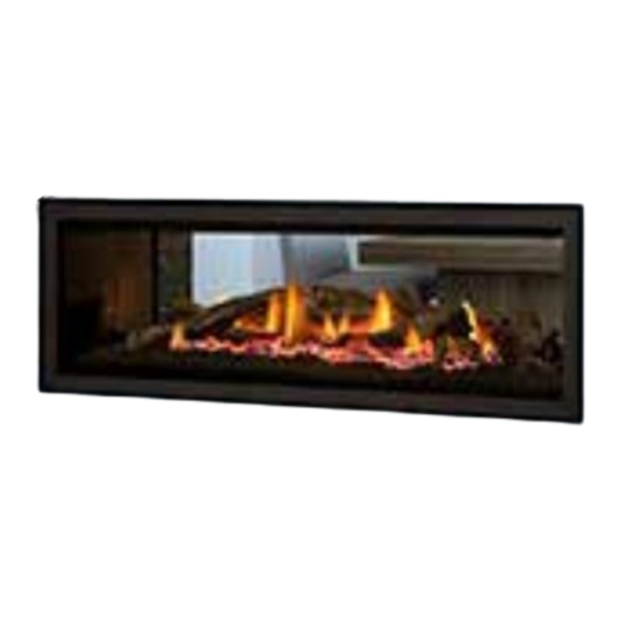
Greenfire
Gas Fireplace
www.regency-fire.com.au
WARNING:
If the information in these instructions are not followed
exactly, a fire or explosion may result causing property
damage, personal injury or loss of life.
FOR YOUR SAFETY
Do not store or use petrol or other flammable vapors and
liquids in the vicinity of this or any other appliance.
Installation and service must be performed by a qualified
installer, service agency or the gas supplier.
919-670h
GF1500LST
®
Installer: Please complete the details on the back cover
and leave this manual with the homeowner.
Homeowner: Please keep these instructions for future reference.
Owners &
Installation Manual
MODELS:
GF1500LST-NG
GF1500LST-LP
GF1500LST-ULPG
LISTINGS AND CODE APPROVALS
These gas appliances have been tested in
accordance with AS/NZS 5263.0 & AS/NZS
5263.1.3 and have been certified by IAPMO
R&T Oceana for installation and operation as
described in these Installation and Operating
Instructions.
Must be installed as per AS/NZS 5601
Your unit should be serviced annually
by an authorised service person.
FOR YOUR SAFETY
What to do if you smell gas:
Do not try to light any appliance.
Do not touch any electrical
switch. Do not use any phone in
your building.
Immediately call your gas
supplier from a neighbour's
phone. Follow the gas supplier's
instructions.
If you cannot reach your gas
supplier, call the fire department.
March 2, 2023
Advertisement
Table of Contents

Subscribe to Our Youtube Channel
Related Manuals for FPI REGENCY Greenfire GF1500LST


Summary of Contents for FPI REGENCY Greenfire GF1500LST
- Page 1 Greenfire GF1500LST ® Owners & Gas Fireplace Installation Manual MODELS: GF1500LST-NG GF1500LST-LP GF1500LST-ULPG LISTINGS AND CODE APPROVALS These gas appliances have been tested in accordance with AS/NZS 5263.0 & AS/NZS 5263.1.3 and have been certified by IAPMO R&T Oceana for installation and operation as described in these Installation and Operating Instructions.
- Page 2 To the New Owner: Congratulations! PAIRING YOUR REMOTE CONTROL You are the owner of a state-of-the-art Gas Fireplace by REGENCY . The GF1500LST has been designed to provide you with ® all the warmth and charm of a wood fireplace at the flick of a switch. The model GF1500LST has been approved by IAPMO R&T Oceana for both safety and efficiency.
- Page 3 WARNING DO NOT turn your fireplace on via any means or allow to be turned on unless you have conducted a thourough inspection of the area sur- rounding the fireplace immediately prior to its use, and you have satisfied yourself that there are no materials or other items in proximity to the fireplace which could present a fire risk.
-
Page 4: Table Of Contents
table of contents Installation Aeration Adjustment ..........31 Pairing the Remote Handset and Control Box ID Code ..2 Conversion Kit from NG to LP/ULPG ......32 Copy of Data Badge ..........5 Optional Fan Ducting Kit Installation ......34 Unit Dimensions ............6 Log Set Installation ..........37 Important Message ..........7 Front Trim Removal / Installation ......39 General Safety Information ........7... -
Page 5: Copy Of Data Badge
data badge This is a copy of the data badge that accompanies each GF1500LST Direct Vent Gas Fireplace. We have printed a copy of the contents here for your review. NOTE: Regency units are constantly being improved. Check the badge on the unit and if there is a difference, the badge on the unit is the correct one. ®... -
Page 6: Unit Dimensions
dimensions UNIT DIMENSIONS 325mm SIDE B 1267mm SIDE A 1532mm 1439mm 39mm 39mm 1152mm SIDE B SIDE A SIDE A Dimension drawings shown without fascias NOTE: DUE TO NATURE AND DESIGN OF THE GF1500LST DOUBLE SIDED UNIT, SIDE A PROJECTS MORE HEAT THAN SIDE B ON THE UNIT. -
Page 7: Important Message
installation 11. Under no circumstances should this appliance IMPORTANT MESSAGE YOUNG CHILDREN SHOULD BE be modified. Parts that have to be removed SAVE THESE INSTRUCTIONS CAREFULLY SUPERVISED WHEN for servicing should be replaced prior to operating this appliance. THEY ARE IN THE SAME AREA AS THE The GF1500LST™... -
Page 8: Installation Checklist
installation This includes: INSTALLATION CHECKLIST 3. The GF1500LST Direct Vent Gas Fireplace can be installed as follows: 1. Clocking the appliance to ensure the correct 1. Locate appliance firing rate (rate noted on label) after burning a) Room location (Refer to "Locating Your appliance for 15 minutes. -
Page 9: Clearances
installation CLEARANCES The clearances listed below are minimum distances unless otherwise stated: A major cause of chimney related fires is failure to maintain required clearances (air space) to combustible materials. It is of the greatest importance that this fireplace and flue system be installed only in accordance with these instructions. Caution Requirements WARNING The sides of the fireplace are defined by standoffs. -
Page 10: Mantel Clearances
installation MANTEL CLEARANCES Combustible Material Due to the extreme heat this fireplace emits, the mantel 330mm 25mm 25mm 330mm clearances are critical. Combustible mantel clearances from top of front facing are shown in the diagram on the right. 305mm 305mm Note: Ensure the paint that is used on the mantel and the facing is "high quality"... -
Page 11: Unit Assembly Prior To Installation
installation UNIT ASSEMBLY PRIOR TO INSTALLATION The nailing strips must be correctly positioned and attached before unit is slid into position. NAILING STRIPS The nailing strips come attached to the unit. The top and side nailing strips are secured to the framing. IMPORTANT NOTE Framing depth measurement is noted with the nailing strips set as far forward on the firebox as possible. -
Page 12: Framing Dimensions
installation FRAMING DIMENSIONS GF1500LST Framing Dimensions Framing Depth * 516mm **minus the combined material thickness of both sides Framing Height 1011mm Framing Width 1545mm Gas Connection Height 87mm Gas Connection Inset 124mm Gas Connection Opening 89mm Width Gas Connection Opening 67mm Height Minimum height to... -
Page 13: Optional Framing Kit
GF1500LST installation OPTIONAL FRAMING KIT OPTIONAL FRAMING KIT 2 Install the 2 long horizontal studs, secure with 2 screws on each end. An optional framing kit is available for the GF1500LST. Note: There are diff erent confi gurations for horizontal exit venting vs vertical exit venting and options in the framing width to accommodate various thick- nesses of fi... - Page 14 installation GF1500LST 4. Set unit in place, center within framing from each side and also back to 6. Completed framing kit. front–install 2 (two) wide studs above and below the unit as shown with 2 (two) screws on each side - repeat on opposite side. Wide Studs 5.
-
Page 15: Non Combustible Facing Installation
installation NON COMBUSTIBLE FACING INSTALLATION IMPORTANT NOTE: IMPORTANT Prior to installation of non-combustible materials by oth- Regency Fireplace Products are designed, produced, tested, and certified to the highest industry standards. The finishing of the walls surrounding ers, check and inspect carefully for any hairline cracks and Regency is as critical as the installation itself. -
Page 16: Framing & Finishing
installation FRAMING & FINISHING 1. Frame in the enclosure for the unit with framing material. Note: It is beneficial to install the unit, gas connection and flue to the unit prior to the wall facing being installed. 2. For exterior walls, insulate the enclosure to the same degree as the rest of the house, apply vapour barrier and plasterboard, as per local installation codes. -
Page 17: Combustible Requirements
installation FRAMING & FINISHING Finished Nailing Strip Material Position 12mm 25mm Nailing Strip 25mm Forward Unit 25mm 12mm Nailing Strip 12mm Forward Note: Unit The siding nailing strips are factory set at 12 mm. The top nailing strip is fixed during transit to the rear of the appliance. 38mm 0mm (flush) Note:... -
Page 18: Exterior Flue Termination Locations
installation EXTERIOR FLUE TERMINATION LOCATIONS FIGURE 6.2 (in part): LOCATION OF FLUE TERMINALS OF BALANCED FLUE AS/NZ 5601, ROOM-SEALED, FAN ASSISTED, OR OUTDOOR APPLIANCE Regency GF1500LST Gas Fireplace... -
Page 19: Clearances
installation CLEARANCES Minimum clearances (mm) Ref. Item Natural Draught Assisted Below eaves, balconies and other projections: Appliances up to 50 MJ/h input Appliances over 50 MJ/h input From the ground, above a balcony or other surface* From a return wall or external corner* From a gas meter (M) (see Note 5) (see Clause 5.11, 5.9 for vent terminal location of regulator) 1000... -
Page 20: Flue Restrictor Settings
installation FLUE RESTRICTOR SETTINGS Screw Positions Flue restriction is required for certain flueing installations, see the diagrams in the "Flueing Arrangements" section to determine if they are required for your installation. The Flue Restrictor plate is located on the inside top of the firebox. To set the flue restriction as indicated in the flueing arrangements diagrams, refer to the following instructions;... -
Page 21: Flueing Arrangements
Flue Terminal Locations diagram from the "Exterior Flue Termination Locations" section. Regency Direct Vent (Flex) System Termination Kits includes all the parts needed to install the GF1500LST using a flexible vent. ® FPI Kit # Length Contains: #946-615 1.2 m... -
Page 22: Rigid Pipe Flueing Systems
installation RIGID PIPE FLUEING SYSTEMS BASIC HORIZONTAL & VERTICAL TERMINATIONS Rigid Pipe Flue Systems offer a complete line of component parts for installation of both horizontal VerticalTerminal and vertical installations. Many items are offered in decorative black, as well as galvanized finish. The minimum components required for a basic Horizontal Termination are: Flashing... -
Page 23: Flueing Introduction
installation FLUEING INTRODUCTION The GF1500LST uses the "balanced flue" technology Co-Axial system. The inner liner vents products of combustion to the outside while the outer liner draws outside combustion air into the combustion chamber thereby eliminating the need to use heated room air for combustion and losing warm room air up the flue. -
Page 24: Horizontal Venting With Two (2) 90 Elbows
Notes: 1. Liner sections should be continuous without any joints or seams. 2. Only Flex pipe purchased from FPI may be used for Flex installations. 3. Horizontal flue must be supported every 0.9 m. 4. A wall thimble is mandatory for all horizontal terminations due to high temperatures. -
Page 25: Installation Instructions Gf1500Lst
installation FLO-MET DIRECT FLUE TOP EXIT VERTICAL FLUE KIT INSTALLATION INSTRUCTIONS GF1500LST This flue kit has been manufactured for use with GF1500LST and to be installed in accordance with AS/NZS 5601. To ensure safety and correct unit operation this flue kit must be installed as outlined in these instructions. Heater and flue clear- ances from combustible materials must be in accordance with these instructions and AS/NZS 5601. -
Page 26: Venting Arrangements
installation VENTING ARRANGEMENTS ALLOWABLE VERTICAL TERMINATIONS The shaded area in the diagram shows all allowable combinations of straight vertical and offset to vertical Horizontal (Metres) terminations, using two 90 elbows, with Rigid Pipe Venting Systems. Two 45 elbows equal to one 90 elbow. -
Page 27: Unit Installation With Horizontal Termination
installation UNIT INSTALLATION WITH 7. Ensure that the pipe clearances to com- bustible materials are maintained (Diagram HORIZONTAL TERMINATION 3). Install the termination cap. (Rigid Flue Systems) The four wood screws provided should be re- A top clearance of 76mm and side & bottom placed with appropriate fasteners for stucco, clearance of 51mm must be maintained;... -
Page 28: Unit Installation With Vertical Termination
installation UNIT INSTALLATION WITH Note: For best results and optimum Roof Pitch Minimum Flue Height performance with each approved VERTICAL TERMINATION flueing system, “Mill-Pac” sealant Meters (Rigid Systems) to every inner pipe connection. flat to 30.26 0.61 Failure to do so may result in Note: A clearance of 51mm must be drafting or performance issues not maintained. -
Page 29: Unit Installation
installation 8) Do the same with the 203mm liner. UNIT INSTALLATION NOTE: Horizontal sections must be supported at intervals not exceeding (With Horizontal Termination 9) Apply a bead of silicone between the thimble 0.9 meter. (Flame picture and Flex System) and termination and around the outer edge performance will be affected by of the terminal at the wall in order to keep... -
Page 30: High Elevation
installation PILOT ADJUSTMENT GF1500LST-NG SYSTEM DATA NOTE: Do not screw in nut too far. If no pressure increases after two full terms, Min. Supply Pressure 1.13 kPa Periodically check the pilot flames. Correct place manometer on inlet test point on flame pattern has two strong blue flames: Low Setting Man. -
Page 31: Wiring Diagram
installation WIRING DIAGRAM DISCONNECT POWER SUPPLY TO UNIT PRIOR TO WORKING ON ELECTRICAL COMPONENTS. ORANGE BLUE MODULATING VALVE GREEN ORANGE COIL BROWN SIGMA 845 BROWN BROWN BROWN (NO) BROWN BROWN (NO) BROWN BROWN SPARKER PRESSURE SWITCH FAN 1 BROWN PRESSURE SWITCH FAN 2 MODULE - SPARK PILOT FLAME... -
Page 32: Conversion Kit From Ng To Lp/Ulpg
GF1500LST installation CONVERSION KIT FROM NG TO LP/ULPG CONVERSION KIT FROM NG TO ULPG FOR GF1500LST USING SIT 845 NOVA GAS VALVE FOR GF1500LST USING SIT 845 NOVA GAS VALVE THIS CONVERSION MUST BE DONE BY A QUALIFIED GAS FITTER IF IN DOUBT DO NOT DO THIS CONVERSION !! 5. - Page 33 GF1500LST installation 9. Reinstall new burner orifi ce LP/ULPG and tighten. NOTE: Do not screw in nut too far. If no pressure increases after two full turns, Place manometer on inlet test point on gas 10. Replace the yellow "NG" label with the red "LP or ULPG" label. valve and check fl...
-
Page 34: Optional Fan Ducting Kit Installation
installation GF1500 OPTIONAL FAN DUCTING KIT INSTALLATION OPTIONAL FAN DUCTING KIT INSTALLATION LISTINGS AND CODE GENERAL INFORMATION Maximum Duct Run: 9.0m Kit Contains 4.5m APPROVALS The Fan Kit increases the effectiveness of your fireplace by dispersing warm air from the fireplace If you require more than 4.5m please purchase Fan This Fan Kit has been approved for use with Duct Extension Kit. - Page 35 installation GF1500 OPTIONAL FAN KIT INSTALLATION 9. On the top of the unit, bend the 3 tabs up. Insert the NOTE: Installation of Fan Kit should be done prior Duct collar. Secure the collar to the 3 tabs with screws. Air Duct to installation of the wall.
- Page 36 OPTIONAL FAN KIT INSTALLATION FAN DUCT EXTENSION KIT installation In order to use the fan extension duct kit, you must have fan kit. This kit allows you to extend the fan duct to 9m. 2. Attach the 4.5m duct within this kit to the connecting collar on the opposite 1.
-
Page 37: Log Set Installation
GF1500LST installation LOG SET INSTALLATION LOG SET INSTALLATION Read the instructions below carefully and refer to the images. If the logs are broken do not use the unit until they are replaced. Broken logs can interfere with pilot operation. Improper positioning of the logs may create carbon build-up and can alter the unit's performance which is not covered under warranty. Log kit # 696-930 contains the following pieces: Side B Description... - Page 38 GF1500LST installation 5. Place Log 5 in the landing spot in the burner, located on the far right 8. Place Log 8 in the landing spot in the burner, located on the left side of side of Log 1 as shown in Diagram 5. Place embers on burner - loca- Log 1 as shown in Diagram 9.
-
Page 39: Front Trim Removal / Installation
installation FRONT TRIM REMOVAL / INSTALLATION 1. Remove faceplate, inner door frame, and glass door if already installed - see instructions in this manual. 2. Lift out 2 side panels and remove two (2) screws in locations shown below to remove front trim piece. 3. -
Page 40: Faceplate And Deflector Installation
GF1500 installation FACEPLATE AND DEFLECTOR INSTALLATION FACEPLATE AND DEFLECTOR INSTALLATION 1. Install the fascia to the unit by hooking the left and right side 5 screws mounting brackets into the mounting slots at the side of the firebox as shown below. Diagram 4 Diagram 4 3 Mounting Slots... -
Page 41: Screen & Inner Door Frame Installation
installation SCREEN & INNER DOOR FRAME INSTALLATION 1. Hang Screen Mesh over Inner Door Frame as shown in Diagram 1. 3. Install Screen and Inner Door Frame to unit but hanging over glass door frame as shown in Diagram 3. Lower gently once in position over glass door frame. -
Page 42: Finishing Trim Installation
installation FINISHING TRIM INSTALLATION 1. Install the finishing trim by lining up trim with the outside of the fascia. Press trim inward firmly to seat onto the unit. Finishing Trim Installed 2. Pull trim outward–away from the unit to remove. Regency GF1500LST Gas Fireplace... -
Page 43: Operating Instructions Operating Instructions
operating instructions OPERATING SUMMARY OF FIRST FIRE INSTRUCTIONS CONTROLS The FIRST FIRE in your heater is part of the Before operating this appliance, proceed through On/Off Button paint curing process. To ensure that the paint is the following check list. If the unit is switched off, pressing and releas- properly cured, it is recommended that you burn ing this button once will switch the unit ON. -
Page 44: Copy Of Lighting Plate Instructions
operating instructions RESETTING THE UNIT NORMAL OPERATING SOUNDS OF COPY OF LIGHTING PLATE GAS APPLIANCES INSTRUCTIONS If the appliance detects a fault and goes into 'lockout', the control system will need to be rest It is possible that you will hear some sounds from by depressing the reset button. -
Page 45: Maintenance
maintenance FAN SERVICE NOTE: THIS UNIT HAS 2 FANS PRIOR TO SERVICING THE FAN, ENSURE THAT UNIT 7. Remove 2 screws to release fan bracket. HAS COOLED TO ROOM TEMPERATURE, ALL POWER IS DISCONNECTED AND GAS SUPPLY IS TURNED OFF. tooltip 1. -
Page 46: Glass Door Installation
maintenance GLASS DOOR INSTALLATION WARNING: Do not operate the appliance with the glass panels removed, cracked or broken. Replacement of the glass panels should be done by a licensed or qualified service person. Glass should be cool, if cleaning is necessary. There are 2 glass doors on the GF1500LST, one side is removed with a latch tool and the opposite side is removed by removing the screws securing the door. -
Page 47: Valve Tray Replacement
maintenance VALVE TRAY REPLACEMENT 6. Remove 12 screws securing valve tray. PRIOR TO SERVICING THE FAN, ENSURE THAT UNIT HAS COOLED TO ROOM TEMPERATURE, ALL POWER IS DISCONNECTED AND GAS SUPPLY IS TURNED OFF. 1. Remove faceplate, inner frame, glass door, front trim piece and end panels on one side- see instructions in this manual. -
Page 48: Maintenance Instructions
maintenance MAINTENANCE INSTRUCTIONS GLASS GASKET GENERAL FLUE MAINTENANCE If the glass gasket requires replacement use a Conduct an inspection of the flueing system semi- 1. Always turn off the gas valve before cleaning. tadpole glass gasket (Part #846-695). annually. Recommended areas to inspect as For relighting, refer to lighting instructions. -
Page 49: Troubleshooting Guide
maintenance Troubleshooting Guide________________ TROUBLESHOOTING GUIDE ALL WORK MUST BE CARRIED OUT BY A LICENSED/QUALIFIED TECHNICIAN It is critical that this appliance is earthed and that Active and Neutral are not crossed Pilot light models only SYMPTOM CAUSE SOLUTION Unit does not operate No power supply (240V) to Check 240V power supply (No ignition &... - Page 50 maintenance Troubleshooting Guide________________ TROUBLESHOOTING GUIDE Unit ignites, main burner becomes Incorrect burner pressure Adjust burner pressure to correct unstable, flame lifts off burner, unit settings setting (See Data plate) goes into lockout Flue blocked, Incorrect flue Clear blocked flue, install flue installation or flue joints not correctly and seal all flue joints sealed...
-
Page 51: Gas Maintenance
maintenance Gas Maintenance GAS MAINTENANCE - RECOMMENDED ANNUAL ROUTINE Recommended Annual Routine Maintenance for Gas Fireplaces, Stoves and Inserts In order for your Regency appliance to continue to provide comfort to your home periodic maintenance must be performed to ensure it is operating at peak efficiency. The items in the list should be checked by a licensed gas service technician during the annual service check. Your unit may require more frequent maintenance checks if you notice any changes in how it operates. Operational changes to look for can include, but are not limited to, extended start up time, increased fan noise, residue/carbon build up, white build up on the glass/firebox, increased operating noise etc. Should any of these or other conditions arise, discontinue use and schedule a service check with your local licensed gas technician. The list below shows items your licensed service technician will need to check and service at least annually. Clean Inspect Check • Glass • Pilot assembly • Voltage on thermocouple/thermopile (mil- • Interior bricks / panels • Burner livolt models) • Burner ports & burner air shutter •... -
Page 52: Electronic Components
parts list ELECTRONIC COMPONENTS PARTS LIST Note: Depending on the model, the diagram shown below may not depict the actual parts - for reference purposes only. 910-936 910-082 911-146 911-224 (NG) 911-225 (LP) 910-089 910-088 910-912 910-084 911-101 910-526 910-080 911-227 910-514 911-183... -
Page 53: Main Assembly
parts list MAIN ASSEMBLY Part # Description 696-004 Left Ceramic Insulation Filler 696-574/P Valve Assembly - NG Part # Description 696-576/P Valve Assembly - LP 696-052 Right Ceramic Insulation Filler 910-080 845 Sigma Valve Only - NG 696-044 Clip Brick Panel (Each) 910-081 845 Sigma Valve Only - LP 696-066... - Page 54 parts list MAIN ASSEMBLY SIDE A SIDE B Regency GF1500LST Gas Fireplace...
-
Page 55: Accessories
606-Acce UNITS IN INCHES ANGULAR = DATE: E.C.N.: SIGN: THIS DRAWING IS THE PROPERTY OF FPI LTD., IT MAY NOT BE COPIED IN WHOLE OR IN PART, OR DISCLOSED TO A THIRD PARTY WITHOUT OUR PR Regency GF1500LST Gas Fireplace... -
Page 56: Warranty
This warranty will only apply to those products which are acquired at the time of this warranty being effective. FPI will not be liable for any damage or loss that falls outside the scope of the warranty. Revision Date: December 2016... - Page 57 Any part(s) found to be defective during the warranty period as outlined above will be repaired or replaced at FPI’s option through an accredited distributor, dealer or pre-approved and assigned agent provided that the defective part is returned to the distributor, dealer or agent for inspection if requested by FPI. Alternatively, FPI may at its own discretion fully discharge all of its obligations under the warranty by refunding the verified purchase price of the product to the original purchaser.
- Page 58 Limited Lifetime Warranty. FPI has no obligation to enhance or modify any unit once manufactured (i.e. as products evolve, field modifications or upgrades will not be performed on existing appliances).
- Page 59 This Limited Warranty is given at the time of sale and purchase of the relevant fireplace product. The terms of this Limited Warranty may be amended from time to time by FPI in accordance with changes to business practices, consumer laws or other legal requirements. The rights and protections granted under the Limited Warranty are those in force in relation to a fireplace product at the time and in the place of sale of that product, and only those terms will be applicable in respect of that product.
- Page 60 Customers should contact the authorised selling dealer to obtain warranty service. In the event the authorised selling dealer is unable to provide warranty service, please contact FPI by mail at the address listed below. Please include your name, address, purchase date, selling dealer, serial #, type of unit, a brief description of the problem, email and telephone contact information, and a copy of your original tax invoice.
- Page 61 Phone: Email: For purchases made in CANADA: For purchases made in the UNITED STATES: For purchases made in AUSTRALIA: FPI Fireplace Products Fireplace Products US, Inc. Fireplace Products Australia Pty Ltd 99 Colemans Road International Ltd. PO Box 2189 PMB 125 Dandenong South, Vic.
- Page 64 Installer: Please complete the following information Dealer Name & Address: _______________________________________ ___________________________________________________________ Installer: ___________________________________________________ Phone #: ___________________________________________________ Date Installed: _______________________________________________ Serial #: ____________________________________________________ Regency is a registered trademarks of FPI Fireplace Products International Ltd. © Copyright 2023, FPI Fireplace Products International Ltd. All rights reserved.
Need help?
Do you have a question about the REGENCY Greenfire GF1500LST and is the answer not in the manual?
Questions and answers