
Related Manuals for Motorola solutions APX 8000 3.5


Summary of Contents for Motorola solutions APX 8000 3.5
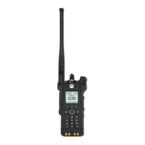
- Page 1 APX TWO-WAY RADIOS APX 8000 Model 3.5 User Guide *MN001425A01* SEPTEMBER 2024 MN001425A01-BB © 2024 Motorola Solutions, Inc. All Rights Reserved.
-
Page 2: Intellectual Property And Regulatory Notices
License Rights The purchase of Motorola Solutions products shall not be deemed to grant either directly or by implication, estoppel or otherwise, any license under the copyrights, patents or patent applications of Motorola Solutions, except for the normal nonexclusive, royalty-free license to use that arises by operation of law in the sale of a product. -
Page 3: Table Of Contents
MN001425A01-BB Contents Contents Intellectual Property and Regulatory Notices..............2 List of Tables........................12 Software Version........................13 Chapter 1: Read Me First....................14 1.1 Notations Used in This Manual......................14 1.2 Radio Care............................14 1.2.1 Cleaning Your Radio......................16 1.2.2 Cleaning the External Surface of the Radio............... 16 1.2.3 Radio Service and Repair.................... - Page 4 MN001425A01-BB Contents 4.7 Alert Tones ............................35 4.8 Phone Call Displays and Alerts......................37 4.9 Display Color Change On Channel....................38 Chapter 5: General Radio Operation................39 5.1 Selecting a Zone..........................39 5.2 Selecting a Radio Channel......................39 5.3 Selecting a Channel by using Channel Search Button..............40 5.4 Mode Select Feature........................40 5.4.1 Saving a Zone and a Channel to a Softkey................41 5.4.2 Saving a Zone and a Channel to a Button.................
- Page 5 MN001425A01-BB Contents 7.2.1.2 Making a Selective Call..................52 7.2.2 Talkgroup Call Feature (Conventional Only)..............52 7.2.2.1 Selecting a Talkgroup................... 52 7.2.3 Sending a Status Call......................53 7.2.4 Making Priority Dispatch Calls................... 53 7.2.5 Dynamic Regrouping (Trunking Only) ................54 7.2.5.1 Classification of Regrouped Radios..............54 7.2.5.2 Requesting a Reprogram (Trunking Only)............54 7.2.6 Dynamic Zone Programming.....................
- Page 6 MN001425A01-BB Contents 7.6.4 Restoring a Nuisance Channel..................67 7.7 Call Alert Paging..........................67 7.7.1 Receiving a Call Alert Page....................68 7.7.2 Sending a Call Alert Page....................68 7.8 Recent Calls.............................69 7.8.1 Viewing Recent Calls......................69 7.8.2 Deleting Calls........................70 7.8.3 Instant Recall........................70 7.8.3.1 Saving and Playback Calls...................70 7.9 In-Call User Alert..........................72 7.10 Emergency Operation........................
- Page 7 MN001425A01-BB Contents 7.14.3 Exiting Fall Alert....................... 83 7.14.4 Reinitiating Fall Alert......................83 7.15 Automatic Registration Service......................83 7.15.1 Selecting or Changing the ARS Mode................84 7.15.2 User Login Feature......................84 7.15.2.1 Logging In as a User..................84 7.15.2.2 Logging Out......................85 7.16 Text Messaging Service......................... 86 7.16.1 Accessing the Messaging Features.................
- Page 8 MN001425A01-BB Contents 7.18.3.5 Erasing Encryption Keys.................. 100 7.18.3.6 Requesting an Over-the-Air Rekey..............101 7.18.3.7 MDC OTAR (Conventional Only)..............101 7.18.3.8 Infinite UKEK Retention..................102 7.18.3.9 Hear Clear......................102 7.19 Radio Lock........................... 102 7.19.1 Enabling or Disabling Radio Lock (Secure Radios Only)..........103 7.19.2 Changing the Radio Lock Password................103 7.19.3 Changing the Tactical Inhibit Password.................
- Page 9 MN001425A01-BB Contents 7.24.3 Out-of-Range Radio....................... 116 7.24.4 SmartConnect.........................116 7.24.5 Site Trunking Feature..................... 117 7.24.6 Site Search........................117 7.24.7 Locking and Unlocking a Site..................117 7.24.8 Viewing the Current Site....................117 7.24.9 Changing the Current Site....................118 7.25 Mission Critical Wireless Bluetooth ® Wireless Technology ............118 7.25.1 Pairing with Low Frequency-Motorola Proximity Pairing (LF-MPP) Feature....
- Page 10 MN001425A01-BB Contents 7.30.2 Selecting a Basic Zone Bank..................132 7.30.3 Selecting the Power Level....................133 7.30.4 Selecting a Radio Profile....................133 7.30.4.1 Selecting an Enhanced Zone Bank..............134 7.30.5 Enabling and Disabling the Radio Alias................. 134 7.30.6 Controlling the Display Backlight..................134 7.30.7 Locking and Unlocking the Keypad and Controls............135 7.30.8 Turning the Controls and Keypad Buttons Tones On or Off...........
- Page 11 Declaration of Compliance for the Use of Distress and Safety Frequencies........154 Technical Parameters for Interfacing External Data Sources.............. 154 Limited Warranty......................155 MOTOROLA SOLUTIONS COMMUNICATION PRODUCTS..............155 I. WHAT THIS WARRANTY COVERS AND FOR HOW LONG:............155 II. GENERAL PROVISIONS:....................... 156 III. STATE LAW RIGHTS:........................156 IV.
-
Page 12: List Of Tables
MN001425A01-BB List of Tables List of Tables Table 1: Text Entry Modes..........................23 Table 2: LED Indications........................... 29 Table 3: TMS Status Icons..........................33 Table 4: Call Type Icons............................34 Table 5: ViQi Virtual Partner Queries........................ 50 Table 6: MPL Selection Mode........................... 58 Table 7: Emergency Operation Scenarios...................... -
Page 13: Software Version
MN001425A01-BB Software Version Software Version All the features described in the following sections are supported by the software version R34.00.00 or later. Accessing the Radio Information on page 140 to determine the software version of your radio. Contact your system administrator for more details of all the supported features. -
Page 14: Chapter 1: Read Me First
MN001425A01-BB Chapter 1: Read Me First Chapter 1 Read Me First This User Guide covers the basic operation of the radio. However, your dealer or system administrator may have customized your radio for your specific needs. Check with your dealer or system administrator for more information. - Page 15 (For APX 8000 R Radios Only) Elastomer seals used in portable radios age with time and environmental exposure. To ensure the waterseal integrity of the radio, Motorola Solutions recommends that radios be checked annually as a preventive measure. The disassembly, test, and reassembly procedures along with necessary test equipment are available in the Service Manual.
-
Page 16: Cleaning Your Radio
Through its maintenance and installation program, Motorola Solutions makes the finest service available to those desiring reliable continuous communications on a contract basis. For a contract service agreement, contact your nearest Motorola Solutions service or sales representative, or an authorized Motorola Solutions dealer. -
Page 17: What Your Dealer Or System Administrator Can Tell You
MN001425A01-BB Chapter 1: Read Me First What Your Dealer or System Administrator Can Tell You If the radio is to be operated in extreme temperatures (less than -30 °C or more than +60 °C), check with your system administrator for the correct radio settings. You can consult your dealer or system administrator about the following: ●... -
Page 18: Chapter 2: Getting Started
Do not discard batteries in a fire. When and where to use: Motorola Solutions-approved battery shipped with your radio is uncharged. Prior to using a new battery, charge it for a minimum of 16 hours to ensure optimum capacity and performance. For a... -
Page 19: Attaching The Antenna
MN001425A01-BB Chapter 2: Getting Started Attaching the Antenna Prerequisites: Ensure the radio is turned off before attaching the antenna. Procedure: 1. Set the antenna in the receptacle. 2. Turn the antenna clockwise to attach to the radio. 3. To remove the antenna, turn the antenna counterclockwise. NOTE: When removing the antenna, ensure that the radio is turned off. -
Page 20: Turning On The Radio
MN001425A01-BB Chapter 2: Getting Started Turning On the Radio Procedure: 1. Rotate the On/Off/Volume Control Knob clockwise until you hear a click. ● If the power-up test is successful, you see a splash screen on the radio display, followed by the Home screen and the Codeplug Alias. -
Page 21: Chapter 3: Radio Controls
MN001425A01-BB Chapter 3: Radio Controls Chapter 3 Radio Controls This chapter explains the buttons and functions to control the radio. Radio Parts and Controls Antenna LED Indicator... - Page 22 MN001425A01-BB Chapter 3: Radio Controls Top (Orange) Button This button is usually programmed as the Emergency button. Microphone Accessory Connector Home Button Press to return to the Home screen. 4-Way Navigation Buttons Use these buttons for list scrolling and navigating around the menu hierarchy. Battery Latch Keypad Use the keypad to enter alphanumeric characters for dialing, contact entries, and text...
-
Page 23: Text Entry Icons
MN001425A01-BB Chapter 3: Radio Controls Main Speaker Microphone Top Display 16-Position Select Knob This knob is usually programmed for channel selection. Text Entry Icons This feature only supports Model 3.5. Your radio uses icons to indicate the selected text entry mode. Table 1: Text Entry Modes Icon Description... - Page 24 MN001425A01-BB Chapter 3: Radio Controls Bluetooth Audio Reroute Toggles the audio route between the radio speaker or the Remote Speaker Microphone and the Bluetooth headset. Bluetooth Headset PTT Keys up the Bluetooth Headset microphone. Bluetooth Data Devices Pairs your radio with other data devices for data transfer. Bluetooth Clear All Pairing Clears all Bluetooth pairing information on your radio.
- Page 25 MN001425A01-BB Chapter 3: Radio Controls Mode Select (MS01– MS13) Long press – Saves the current zone and channel to one of the Mode Select menus when the Preconfigurable Preset Zone and Channel field is enabled. Short press – Changes to the preset Mode Select zone and channel. Monitor (Conventional Only) Monitors a selected channel for all radio traffic until the function is disabled.
-
Page 26: Assignable Settings Or Utility Functions
MN001425A01-BB Chapter 3: Radio Controls Site Display/Search (Trunking Only) Short press – Displays the current site ID and Received Signal Strength Indicator (RSSI) value. Long press – Performs site search for Automatic Multiple Site Select (AMSS) or SmartZone operation (long press). Site Lock/Unlock (Trunking Only) Allows your radio to lock onto a specific site. -
Page 27: Chapter 4: Status Indicators
MN001425A01-BB Chapter 4: Status Indicators Chapter 4 Status Indicators This section explains the status indicators of the radio. Battery Charge Status Your radio indicates the battery charge status through LED, sounds, and the battery icon on the display. You can also check the battery charge status by using the menu entry. Battery Protection is activated when the battery is low or operating in extremely low temperatures to extend radio communication. -
Page 28: Accessing The Battery Info Screen
MN001425A01-BB Chapter 4: Status Indicators Gauge Battery Charge 11% to 25% Top Display: 10% or less (The gauge begins blinking at 10%) Top Display: 4.1.2 Accessing the Battery Info Screen This feature displays the current capacity and charges cycles of your battery when an IMPRES battery is powering your radio. -
Page 29: Led Indications
MN001425A01-BB Chapter 4: Status Indicators ● The red LED blinks continuously. NOTE: The radio alerts you when NNTN8921and NNTN8930 batteries are attached to the radio because these batteries are not supported. The radio is not HAZLOC-certified and resets if these batteries are used. Refer to the radio FM or UL Manual for more information. - Page 30 MN001425A01-BB Chapter 4: Status Indicators Icon Description The radio is receiving a call or data. Top Display: The radio is transmitting a call or data. Top Display: The radio received an Individual Call. For IMPRES 2 battery operation only – the icon shown indicates the charge remain- ing in the battery.
- Page 31 MN001425A01-BB Chapter 4: Status Indicators Icon Description The radio is scanning a scan list. Top Display: Blinking dot The radio detects activity on the designated Priority-One channel. Top Display: Steady dot The radio detects activity on the designated Priority-Two channel. Top Display: On steady The radio is in View mode...
- Page 32 MN001425A01-BB Chapter 4: Status Indicators Icon Description Secure operation. Top Display: Clear operation. Blinking Receiving an encrypted voice call. The radio is operating in an Advanced Encryption Standard (AES) secure chan- nel. The AES operation is cleared. Blinking The radio is receiving an AES-encrypted voice call. The Global Position System (GPS) feature is enabled, and the signal is available.
-
Page 33: Tms Status Icons
MN001425A01-BB Chapter 4: Status Indicators Icon Description The radio is receiving the broadband signal. The radio is transmitting the broadband signal. The radio is receiving and transmitting the broadband signal. The ARS user logged on successfully with the broadband system. The radio is receiving a broadband signal with the ARS user logged on. -
Page 34: Call Type Icons
MN001425A01-BB Chapter 4: Status Indicators Icon Description The message has normal priority without a request for reply. The Request Reply feature is toggled on before the message is sent. The Priority feature is toggled on before the message is sent. The message is urgent and requires a reply. -
Page 35: Intelligent Lighting Indicators
MN001425A01-BB Chapter 4: Status Indicators Intelligent Lighting Indicators This feature temporarily changes the backlight of the top display screen to help signal that a radio event has occurred. This feature temporarily changes the backlight of the top display screen, and adds a color bar to the main display screen to help signal that a radio event has occurred. - Page 36 MN001425A01-BB Chapter 4: Status Indicators You Hear Tone Name Heard Long, Low- Time-Out Timer Timed After time out. Pitched Tone Talk Prohibit/PTT Inhibit (When PTT button is pressed) transmissions are not al- lowed. Lack of Voice PTT Time When the radio ends your call after it detected there is lack of voice for 60 seconds after the PTT is pressed and hold.
-
Page 37: Phone Call Displays And Alerts
MN001425A01-BB Chapter 4: Status Indicators You Hear Tone Name Heard Two High- GPS Fails When the GPS fails or loses signal. Pitched Tones Ringing Fast Ringing When system is searching for target of Private Call. Enhanced Call Sent When waiting for target of Private Call to answer the call. Phone Call Received When a land-to-mobile phone call is received. -
Page 38: Display Color Change On Channel
MN001425A01-BB Chapter 4: Status Indicators You Hear You See When Notes Phone busy The phone system is Press to exit the phone mode and try busy. your call later. A Busy Tone Phone busy When a channel is not The radio automatically connects when a available. -
Page 39: Chapter 5: General Radio Operation
MN001425A01-BB Chapter 5: General Radio Operation Chapter 5 General Radio Operation This chapter explains the general operations of your radio. Selecting a Zone When and where to use: A zone is a group of channels. NOTE: Any reference to Zone Select Switch refers to Zone Select using the Menu. Do one of the following to select a radio channel. -
Page 40: Selecting A Channel By Using Channel Search Button
MN001425A01-BB Chapter 5: General Radio Operation a. Rotate the preprogrammed 16–Position Select Knob to the desired channel. ● Select a channel using the radio menu Chan : or to Chan. b. Press the Menu Select button directly below Chan . to the required channel or use the keypad to enter the channel number. -
Page 41: Saving A Zone And A Channel To A Softkey
MN001425A01-BB Chapter 5: General Radio Operation The Mode Select feature allows you to save the current zone and channel on your radio to one of the Mode Select feature menus (MS01–MS05) on a programmable side button (MS01–MS13). When programmed, pressing the button changes the transmission to the saved zone and channel. When the Preconfigurable Preset Zone and Channel field is enabled, pressing and holding the preferred Mode Select menu saves the current zone and channel to one of the Mode Select menus. -
Page 42: Receiving And Responding To A Radio Call
MN001425A01-BB Chapter 5: General Radio Operation Receiving and Responding to a Radio Call Once you have selected the required channel and/or zone, you can proceed to receive and respond to calls. The radio shows different indicators based on the system the radio is configured. ●... -
Page 43: Receiving And Responding To A Telephone Call (Trunking Only)
MN001425A01-BB Chapter 5: General Radio Operation 3. Press or the Call Response button to hang up and return to the Home screen. Result: 5.5.3 Receiving and Responding to a Telephone Call (Trunking Only) This feature allows you to receive calls similar to standard phone calls from a landline phone. When and where to use: When you receive a Telephone Call, you hear a telephone-type ringing and the LED blinks green. -
Page 44: Making A Private Call (Trunking Only)
MN001425A01-BB Chapter 5: General Radio Operation 5.6.2 Making a Private Call (Trunking Only) When and where to use: This feature allows you to send an individual Call Alert or page if there is no answer from the target radio. Procedure: 1. -
Page 45: Making A Telephone Call (Trunking Only)
MN001425A01-BB Chapter 5: General Radio Operation ● to the required ID. ● Use the keypad to enter the required ID. 3. Press the PTT button to initiate the Private Call. The display shows Calling... <Number>. 4. Hold the radio vertically 1 to 2 inches (2.5 to 5.0 cm) from your mouth. When you are connected, the display shows the ID of the target radio. -
Page 46: Monitor Feature
MN001425A01-BB Chapter 5: General Radio Operation to bypass the repeater and connect directly to another radio. The transmit and receive frequencies are the same. Procedure: Perform one of the following actions: ● Press the preprogrammed Repeater/Direct switch to toggle between talkaround and repeater mode. ●... -
Page 47: Monitoring Conventional Mode
MN001425A01-BB Chapter 5: General Radio Operation d. Press and hold the PTT button to transmit. The LED lights up solid red. e. Release the PTT button to receive (listen). 5.8.2 Monitoring Conventional Mode This feature allows you to monitor channel traffic on conventional channels by defeating the coded squelch. Thus, you can listen to another active user on the channel. -
Page 48: Chapter 6: Additional Performance Enhancement
MN001425A01-BB Chapter 6: Additional Performance Enhancement Chapter 6 Additional Performance Enhancement The following performance enhancements are some of the latest creations designed to enhance the security, quality, and efficiency of the radios. ASTRO 25 Enhanced Data ASTRO 25 Enhanced Data is optimized to handle different message sizes and variable update rates from different applications of the radio. -
Page 49: P25 Digital Vehicular Repeater System
P25 Digital Vehicular Repeater System Motorola Solutions offers an MSI Certified APX compatible, third party, P25 Digital Vehicular Repeater System (DVRS). This provides low-cost portable radio coverage in areas where only mobile radio coverage is available. -
Page 50: Chapter 7: Advanced Features
MN001425A01-BB Chapter 7: Advanced Features Chapter 7 Advanced Features This chapter explains the operations of the features available in your radio. ViQi ViQi is a virtual assistant that helps you manage your radio and perform information lookups using voice commands. This feature is purpose-built for public safety and is active when you press the assigned ViQi button on the radio, Remote Speaker Microphone (RSM), or compatible mobile microphone. -
Page 51: Using Viqi Virtual Partner
MN001425A01-BB Chapter 7: Advanced Features Query Examples “Am I still at the <location>?” NOTE: ViQi will ask for more information to complete the query. Target Location “Where is <unit name>?” “Tell me where <unit name> is.” NOTE: ViQi will ask for more information to complete the query. 7.1.1 Using ViQi Virtual Partner Prerequisites:... -
Page 52: Making A Selective Call
MN001425A01-BB Chapter 7: Advanced Features The speaker unmutes. Procedure: 1. Hold the radio vertically 1 to 2 inches (2.5 to 5.0 cm) from your mouth. 2. Press and hold the PTT button to talk. Release the PTT button to listen. 7.2.1.2 Making a Selective Call Prerequisites: Your radio must be preprogrammed for you to use this feature. -
Page 53: Sending A Status Call
MN001425A01-BB Chapter 7: Advanced Features 2. Perform one of the following actions: ● to Preset for the preset preprogrammed Talkgroup. ● to the required talkgroup. ● Use the keypad to enter the number of the corresponding Talkgroup in the list. 3. -
Page 54: Dynamic Regrouping (Trunking Only)
MN001425A01-BB Chapter 7: Advanced Features Priority Talkgroup.Priority Dispatch is not available during Emergency operations. Scan feature is suspended when Priority Dispatch is initiated. Prerequisites: Dispatch console that supports this feature must be preprogrammed to use this feature. Check with your dealer or system administrator for more information on dispatch console supporting this feature. -
Page 55: Dynamic Zone Programming
MN001425A01-BB Chapter 7: Advanced Features Procedure: Perform one of the following actions: ● Press the preprogrammed Reprogram Request button to send a reprogram request to the dispatcher. ● or to Rpgm then press the Menu Select button directly below Rpgm to send reprogram request to the dispatcher. -
Page 56: Saving A Channel In The Dynamic Zone From List Selection
MN001425A01-BB Chapter 7: Advanced Features 7.2.6.2 Saving a Channel in the Dynamic Zone from List Selection Prerequisites: To perform this operation, the radio must be in the Dynamic Zone. Procedure: or to ZnPr. Press the Menu Select button directly below ZnPr to enter the Program Zone screen. 2. -
Page 57: Deleting A Channel In The Dynamic Zone
MN001425A01-BB Chapter 7: Advanced Features 7.2.6.4 Deleting a Channel in the Dynamic Zone Prerequisites: To perform this operation, the radio must be in the Dynamic Zone. Procedure: or to ZnPr then press the Menu Select button directly below ZnPr to enter Program Zone screen. The display shows the dynamic channels list. -
Page 58: Multiple Private Line
MN001425A01-BB Chapter 7: Advanced Features ● If you select multi-source zones, the radio displays Confirm target and shows the automatically selected target zones and source zones mapping. ● If the selected multi-source zones exceed the last clonable target zone, the radio displays <#> src zones unselected and Sel exceed max tgt zone alternatively. -
Page 59: Remote Monitor
MN001425A01-BB Chapter 7: Advanced Features 2. Tap the required MPL. The Radio Control Widget displays the selected MPL. Remote Monitor This feature allows the system administrator to turn on the microphone of a targeted radio with a subscriber alias or ID. When remote monitor feature is activated, the audio transmission can be configured in Customer Programming Software (CPS) to route the audio to the radio internal microphone, wired Remote Speaker Microphone (RSM), or Bluetooth wireless microphone. -
Page 60: Adding A New Contact Entry
MN001425A01-BB Chapter 7: Advanced Features Procedure: or to Cnts and press the Menu Select button directly below Cnts. The entries are alphabetically sorted. to the required subscriber alias. 3. Perform one of the following actions: ● Press the Menu Select button directly below Optn and proceed to the next step. ●... -
Page 61: Deleting A Contact Entry
MN001425A01-BB Chapter 7: Advanced Features To cancel this operation, press the Menu Select button directly below Cncl to return to the previous screen. 8. Perform one of the following actions per the information you need to add to current name: ●... -
Page 62: Removing A Contact From A Call List
MN001425A01-BB Chapter 7: Advanced Features 7.4.5 Removing a Contact from a Call List Procedure: or to Cnts and press the Menu Select button directly below Cnts . The entries are alphabetically sorted. to the entry you want to delete and press the Menu Select button directly below Optn . to Rm frm CallLst and press the Menu Select button directly below Sel . -
Page 63: Editing A Call Type
MN001425A01-BB Chapter 7: Advanced Features The entries are alphabetically sorted. to the entry you want to edit and press the Menu Select button directly below Optn . to Edit and press the Menu Select button directly below Sel . to the entry ID you wish to change and press the Menu Select button directly below Edit . A blinking cursor appears. -
Page 64: Scan Lists
MN001425A01-BB Chapter 7: Advanced Features Scan Lists Scan lists are created and assigned to individual channels or groups. Your radio scans for voice activity by cycling through the channel or group. The sequence of scan is as specified in the scan list for the current channel or group. -
Page 65: Changing The Scan List Status
MN001425A01-BB Chapter 7: Advanced Features ● Press the Menu Select button directly below Del to delete the currently displayed channel from the scan list. ● Press the Menu Select button directly below Rcl to view the next member of the scan list. 4. -
Page 66: Scan
MN001425A01-BB Chapter 7: Advanced Features ● Press the Select button one or more times to toggle between different status of the Scan List status icon of the current displayed channel. The radio shows one of following priority status icons and scenarios: ●... -
Page 67: Deleting A Nuisance Channel
MN001425A01-BB Chapter 7: Advanced Features a. When the radio locks onto the channel designated as the new Priority-Two channel, press the preprogrammed Dynamic Priority button. The radio continues scanning the remaining channels in the list. 7.6.3 Deleting a Nuisance Channel When and where to use: If a channel continually generates unwanted calls or noise (termed “nuisance”... -
Page 68: Receiving A Call Alert Page
MN001425A01-BB Chapter 7: Advanced Features 7.7.1 Receiving a Call Alert Page When and where to use: When you receive a Call Alert page, you hear four repeating alert tones and the LED blinks green. The call received icons blinks and the display shows Page received. Procedure: Press any button to clear the Call Alert page. -
Page 69: Recent Calls
MN001425A01-BB Chapter 7: Advanced Features or to Call . b. Press the Menu Select button directly below Call . to select the alias or ID, and press the PTT button to initiate the call. If the target radio does not respond after a preprogrammed period, the display shows Send page?. -
Page 70: Deleting Calls
MN001425A01-BB Chapter 7: Advanced Features or to Rcnt. b. Press the Menu Select button directly below Rcnt to access the Recent Calls feature screen. to scroll through the list. d. To view the recent Emergency calls, press the Menu Select button directly below Emer. Press the Menu Select button directly below All to view back all recent calls. - Page 71 MN001425A01-BB Chapter 7: Advanced Features Perform one of the following to save and play back the recorded calls. You can use the options interchangeably depending on your preference and the programmed functions. Procedure: ● Playback and saving the recorded calls using the radio menu: a.
-
Page 72: In-Call User Alert
MN001425A01-BB Chapter 7: Advanced Features Radio displays the playback status. NOTE: Received call overwrites the ongoing record playback. User can short press the programmable button within three seconds to continue the playback and ignore the receiving call. User can short press the programmable button to trigger playback when the radio is receiving call to overwrite the receiving call. -
Page 73: Special Considerations For Emergency Operation
MN001425A01-BB Chapter 7: Advanced Features Fall Alert is an alternate way to activate the Emergency feature. For more information, see Fall Alert on page For more information, contact your system administrator. 7.10.1 Special Considerations for Emergency Operation The following scenarios apply during Emergency operation: Table 7: Emergency Operation Scenarios Scenario Outcome... -
Page 74: Remote Emergency
MN001425A01-BB Chapter 7: Advanced Features Procedure: Perform one of the following actions: If… Then… If the emergency mode is initiated press and hold the Side Button 1 and press the Emergency by other radios, button. If the emergency mode is initiated Perform one of the following actions: by the Supervisor, ●... -
Page 75: Sending Remote Emergency By Entering The User Id
MN001425A01-BB Chapter 7: Advanced Features If your radio does not receive acknowledgment from the target radio, your radio displays a negative notification. 7.10.5.2 Sending Remote Emergency by Entering the User ID Procedure: 1. Press the programmed Remote Emergency button. 2. Press any digit key. 3. -
Page 76: Sending An Emergency Alarm
MN001425A01-BB Chapter 7: Advanced Features Procedure: 1. Press the programmed Remote Emergency button. 2. Press the Fltr menu item button. Result: Your radio displays the filtered call list. 7.10.6 Sending an Emergency Alarm When and where to use: This feature allows you to send a data transmission, which identifies the radio sending the emergency, to the dispatcher. -
Page 77: Sending An Emergency Call With Hot Mic (Trunking Only)
MN001425A01-BB Chapter 7: Advanced Features 7.10.8 Sending An Emergency Call With Hot Mic (Trunking Only) This feature allows you to send an Emergency Call with hot mic to a group of radios. When and where to use: Your radio must be programmed for this type of operation. Your radio microphone is automatically activated, allowing you to communicate with the group of radios without pressing the PTT button. -
Page 78: Sending An Emergency Alarm And Call With Hot Mic
MN001425A01-BB Chapter 7: Advanced Features 2. Hold the radio vertically 1 to 2 inches (2.5 to 5.0 cm) from your mouth. 3. Press and hold the PTT button. Speak clearly into the microphone. 4. Release the PTT button to end the transmission and wait for a response from the dispatcher. 5. -
Page 79: Emergency Find Me
MN001425A01-BB Chapter 7: Advanced Features ● Press and release the PTT button to exit the Silent Emergency Alarm mode and enter regular dispatch or Emergency Call mode. 7.10.12 Emergency Find Me When the radio is in Emergency mode, the Emergency Find Me feature transmits Bluetooth Low Energy (BTLE) signals, and other emergency information to nearby radios. -
Page 80: Entering Fireground Zone Channel (Conventional)
MN001425A01-BB Chapter 7: Advanced Features ● Sending an Emergency Alarm and Call ● Entering or Exiting a Trunking Talkgroup 7.11.1 Entering Fireground Zone Channel (Conventional) Procedure: 1. Upon powering up, one of the following scenarios occurs: ● If the Fireground Zone Channel is set as default, you hear the gurgle tone and the radio displays the home screen. -
Page 81: Sending Evacuation Tone
MN001425A01-BB Chapter 7: Advanced Features ● Press the PTT button. PTT button must be configured in Customer Programming Software (CPS) to enable this function. The radio cancels the indications, a tone sounds and the radio sends an acknowledgment to the command terminal. -
Page 82: Fall Alert
MN001425A01-BB Chapter 7: Advanced Features Emergency Call De-Key Sidetone The radio sounds an alert tone to remind you that the Emergency Mode is still active after you release the PTT button for an Emergency call transmission. The volume of loudness depends on the maximum tone volume set in your radio profile. -
Page 83: Testing Fall Alert
MN001425A01-BB Chapter 7: Advanced Features ● The alert tone is inhibited when you change to a channel with Emergency but no Fall Alert feature. ● The current alert tone is inhibited and is replaced with a different alert tone when you change to a channel with Emergency feature and a different Fall Alert configuration. -
Page 84: Selecting Or Changing The Ars Mode
MN001425A01-BB Chapter 7: Advanced Features 7.15.1 Selecting or Changing the ARS Mode When and where to use: The following methods are options on how to select or change the ARS Mode. The result of all the methods is the same. You can use the options interchangeably depending on your preference and the programmed functions. -
Page 85: Logging Out
MN001425A01-BB Chapter 7: Advanced Features 2. Perform one of the following actions: ● to [ID Entry] and press the Menu Select button directly below Edit to enter ID. A blinking cursor appears on the screen. Use the keypad to type or edit a user name. Press the Menu Select button directly below Ok to submit. -
Page 86: Text Messaging Service
MN001425A01-BB Chapter 7: Advanced Features 2. Perform one of the following actions: ● Select Yes to clear all your private data. The display shows Private data cleared. ● Select No to keep your private data. 7.16 Text Messaging Service This feature only supports Model 3.5 and Model 2.5. Text Messaging Service (TMS) allows you to send and receive messages and run database queries directly from your radios. -
Page 87: Sending A Quick Text Message
MN001425A01-BB Chapter 7: Advanced Features 3. Perform one of the following actions: ● to Compose and press the Menu Select button directly below Sel. ● Press the Menu Select button directly below Exit to return to the Home screen. to Text Message and press the Menu Select button directly below Sel to compose a new message. -
Page 88: Priority Status And Request Reply For New Text Messages
MN001425A01-BB Chapter 7: Advanced Features to Quick Text and press the Menu Select button directly below Sel for a predefined message. to scroll through the list of messages and press the Menu Select button directly below Sel to select the required message. The message appears on the Compose screen, with a blinking cursor at the end of it. -
Page 89: Removing A Priority Status From A Text Message
MN001425A01-BB Chapter 7: Advanced Features to Mark Important and press the Menu Select button directly below Sel to indicate that the message is important. Result: The priority status icon appears beside the normal message icon on the label bar. 7.16.4.2 Removing a Priority Status from a Text Message Prerequisites: Ensure there is an outgoing message composed to allow you to perform this procedure. -
Page 90: Removing A Priority Status And A Reply Request From A Text Message
MN001425A01-BB Chapter 7: Advanced Features to Mark Important and press the Menu Select button directly below Sel to indicate that the message is important. to Req Reply and press the Menu Select button directly below Sel to request for a reply. Result: The priority status and request reply icons appear beside the normal message icon on the label bar. -
Page 91: Replying To A Received Text Message
MN001425A01-BB Chapter 7: Advanced Features ● Press the preprogrammed Data Feature button or the TMS Feature button to access the TMS feature screen. to Inbox and press the Menu Select button below Sel . ● Press and hold the preprogrammed Data Feature button or the TMS Feature button to access the Inbox. -
Page 92: Accessing The Drafts Folder
MN001425A01-BB Chapter 7: Advanced Features to Send Message and press the Menu Select button directly below Sel to send the message. Result: The display shows the Send Message screen and Sending msg. NOTE: Press the Menu Select button directly below Back at any time to return to the previous screen. You can append a priority status and/or a request reply to your message. -
Page 93: Sending A Sent Text Message
MN001425A01-BB Chapter 7: Advanced Features The display shows a list of aliases or IDs, with the recipient of latest sent message on top. to the required aliases or ID and press the Menu Select button below Sel to view the message. -
Page 94: Astro 25 Advanced Messaging Solution
This feature only supports Model 3.5 and Model 2.5. The ASTRO 25 Advanced Messaging Solution allows you to quickly send and receive messages and run database queries directly from your data-enabled Motorola Solutions two-way radios. Federal mandate requires Two-Factor Authentication when querying Federal and State databases. - Page 95 MN001425A01-BB Chapter 7: Advanced Features ● or to User, and press the Menu Select button directly below User. The display shows the User Login screen. 2. Perform one of the following actions: ● to [ID Entry] and press the Menu Select button directly below Edit. A blinking cursor appears.
-
Page 96: Logging Out Of Two-Factor Authentication
MN001425A01-BB Chapter 7: Advanced Features 7.17.1.2 Logging out of Two-Factor Authentication When and where to use: NOTE: Private data refers to all messages in the text messaging Inbox, Draft, and Sent folder. The next user is able to access the Inbox, Draft, and Sent messages if private data is not deleted. Radio that is successfully logged in to the secured system receives advertisement from the server that the access to the data for query is enabled. -
Page 97: Receiving A Query
MN001425A01-BB Chapter 7: Advanced Features to scroll through the list of messages and press the Menu Select button directly below Sel to select the required message. The message appears on the Compose screen, with a blinking cursor at the end of it. 6. -
Page 98: Selecting Secure Transmissions
MN001425A01-BB Chapter 7: Advanced Features 7.18.1 Selecting Secure Transmissions Procedure: Turn the preprogrammed Secure/Clear switch to the secure position. ● If the selected channel is preprogrammed for clear-only operation, when you press the PTT button, you hear an invalid mode tone and the display shows Clear TX only. ●... -
Page 99: Multikey Feature
MN001425A01-BB Chapter 7: Advanced Features The display shows Keyloading and all other radio functions, except for power down, backlight, and volume, are locked out. NOTE: If the Multi-system Over-the-Air Rekeying feature is in use, the ASTRO profile name is displayed below Keyloading. -
Page 100: Selecting Keysets
MN001425A01-BB Chapter 7: Advanced Features 7.18.3.4 Selecting Keysets When and where to use: This feature allows you to select one or more groups of several encryption keys from among the available keys stored in the radio. For example, you could have a group of three keys structured to one keyset, and another group of three different keys structured to another keyset;... -
Page 101: Requesting An Over-The-Air Rekey
MN001425A01-BB Chapter 7: Advanced Features ● Erasing the single key in radios with the single-key option and erasing all keys in radios with the multikey option by using the preprogrammed Top Side (Select) button and Top (Orange) button: a. Press and hold the Top Side (Select) button. b. -
Page 102: Infinite Ukek Retention
MN001425A01-BB Chapter 7: Advanced Features 7.18.3.8 Infinite UKEK Retention This feature enables Unique Key Encryption Key (UKEK) to be permanently stored in the radio even when all the encryption keys are erased. Without this UKEK key, the radio cannot be rekeyed over the air. The Infinite UKEK Retention settings can be different for each secure profile. -
Page 103: Enabling Or Disabling Radio Lock (Secure Radios Only)
MN001425A01-BB Chapter 7: Advanced Features If you exhaust all attempts at entering the correct password, the radio is deadlocked. Restart the radio to start over. NOTE: Depending on the configuration, the radio can carry over the number of attempts remaining even after a power cycle. -
Page 104: Changing The Tactical Inhibit Password
MN001425A01-BB Chapter 7: Advanced Features 7.19.3 Changing the Tactical Inhibit Password The Tactical Inhibit Password is required for the Radio Stun and Radio Kill features. You can set up to eight characters for this password. Procedure: or to Pswd. 2. Press the Menu Select button directly below Pswd. The display shows Change Password screen. -
Page 105: Radio Kill
MN001425A01-BB Chapter 7: Advanced Features 2. Press the Menu Select button directly below Stun. The display shows Enter Password. 3. Use the keypad to enter your Tactical Inhibit Encode Password. 4. Press the Menu Select button directly below Ok . The display shows radio Contact IDs. -
Page 106: Using Direct Kill To Kill Your Own Radio
MN001425A01-BB Chapter 7: Advanced Features ● Press the Menu Select button directly below LNum to go to the last number dialed. ● Use the keypad to enter the required ID. ● Press the Menu Select button directly below Send to initiate command. If the receiving radio received the command, your radio display shows Ack received. -
Page 107: Outdoor Location Feature
MN001425A01-BB Chapter 7: Advanced Features ● For your initial fix, hold the radio in the face position. ● Stay in the open as the GPS feature works best when there is nothing between your radio and the open sky. 7.22.1 Outdoor Location Feature This feature only supports Model 3.5 and Model 2.5. -
Page 108: Accessing The Outdoor Location Feature
MN001425A01-BB Chapter 7: Advanced Features Military Grid Reference System (MGRS) can only be enabled through Customer Programming Software (CPS) configuration. When the MGRS coordinate is enabled, all location coordinates are displayed in the MGRS format, including the editable locations in GPS. 7.22.4 Accessing the Outdoor Location Feature When and where to use:... -
Page 109: Saving A Waypoint
MN001425A01-BB Chapter 7: Advanced Features to the preferred location format and press the Menu Select button directly below Sel. Result: The front display shows the location with the selected format. NOTE: If the SLD99 format is selected and the range is invalid, the display shows –––––– –––––- on the location. -
Page 110: Editing The Alias Of A Waypoint
MN001425A01-BB Chapter 7: Advanced Features ● to select a waypoint to view the location information in full. 4. Press the Menu Select button directly below Optn. 5. To view the MGRS or latitude/longitude location, time and date of the selected waypoint, View and press the Menu Select button directly below Sel. -
Page 111: Deleting A Single Saved Waypoint
MN001425A01-BB Chapter 7: Advanced Features ● to [Home] and press the Menu Select button directly below Optn. ● to [Destination] and press the Menu Select button directly below Optn. to Edit location and press the Menu Select button directly below Sel. The first number blinks. -
Page 112: Deleting All Saved Waypoints
MN001425A01-BB Chapter 7: Advanced Features 7.22.11 Deleting All Saved Waypoints Prerequisites: Ensure your radio shows the current location on the screen. When and where to use: NOTE: You cannot delete any of the preprogrammed waypoints. Procedure: 1. Press the Menu Select button directly below Optn. to Waypoints and press the Menu Select button directly below Sel . -
Page 113: Peer-Location On The Display (Astro Conventional)
MN001425A01-BB Chapter 7: Advanced Features 7.22.14 Peer-Location on the Display (ASTRO Conventional) This feature only supports Model 3.5 and Model 2.5. This feature is only available for radio-to-radio voice transmissions, dispatch call, and selective call. The transmitting radio and receiving radio must be configured to enable the sending and receiving of the Global Positioning System (GPS) coordinates. -
Page 114: Mission Critical Geofence
MN001425A01-BB Chapter 7: Advanced Features When and where to use: When the radio enters a Geofence area, the radio immediately sends a message ACK back to the system. The radio searches the current zone for the channel with same talkgroup assigned as the Dynamic Talkgroup and also with same system ID of current trunk system. -
Page 115: Exiting Mission Critical Geofence
MN001425A01-BB Chapter 7: Advanced Features The radio then connects to the designated talkgroup. The radio displays the talkgroup alias and dynamic regroup tone sounds. The transmit power level changes and the radio shows a direct text message content without any user operation. NOTE: The availability of the Voice Announcement (VA), TMS display, Intelligent Backlight, and Transmit Power Level alerts depend on your radio configuration. -
Page 116: Imbalanced Coverage
SmartConnect. Your radio can connect through a fixed Wi-Fi access point in buildings or in-vehicle Broadband modem such as the following modems: ● Motorola Solutions VML750 ● Sierra Wireless MP70 ● Sierra Wireless GX450 Your radio displays the SmartConnect capable icon on the SmartConnect enabled channel. -
Page 117: Site Trunking Feature
MN001425A01-BB Chapter 7: Advanced Features 7.24.5 Site Trunking Feature If the Zone Controller loses communication with any site, that site reverts to site trunking. When this occurs, you can communicate only with the radios within your trunking site. The display shows the currently selected zone or channel, and the site trunking message. 7.24.6 Site Search When searching for a site, your radio is inoperable. -
Page 118: Changing The Current Site
(your device or accessory). Obstacles that can cause an obstruction in the line-of-sight include trees, buildings, mountains, cars, and others. For high degree of reliability, Motorola Solutions recommends to NOT separate the radio and the accessory. -
Page 119: Pin Authentication In Pairing
MN001425A01-BB Chapter 7: Advanced Features At the fringe areas of reception, both voice and tone quality will start to sound "garbled" or "broken". To correct this problem, simply position the accessory and radio closer to each other (within the 10 meter defined range) to re-establish clear audio reception. -
Page 120: Pairing The Authentication Pin With The Generated Numeric Pin
MN001425A01-BB Chapter 7: Advanced Features When the pairing timer expires, the display shows <Device Friendly Name> pair canceled and return to Home screen. If you choose to accept the pairing process, the display shows Compare PIN: XXXXXX. If you choose to reject the pairing process, the display shows Cancel pairing in progress... followed by <Device Friendly Name>... -
Page 121: Viewing And Clearing The Bluetooth Device Information
MN001425A01-BB Chapter 7: Advanced Features If unsuccessful, one of the following scenarios will occur: ● The display shows <Device Friendly Name> pair failed (if the PIN numbers are different). ● <Device Friendly Name> connect failed (if the connection fails). The display returns to Available Dev screen. 7.25.3 Viewing and Clearing the Bluetooth Device Information Procedure:... -
Page 122: Pairing With Lex Handheld
MN001425A01-BB Chapter 7: Advanced Features to Friendly name and press the Menu Select button directly below Edit. A blinking cursor appears in the Friendly Name screen. 3. Use the keypad to edit the text. 4. Perform one of the following actions: ●... -
Page 123: Holster Sensor
MN001425A01-BB Chapter 7: Advanced Features This feature is enabled through Customer Programming Software (CPS) configuration. For more information, contact your system administrator. NOTE: The radio reports the next event after the programmed 15-second timer expires. Any consecutive event occurring within the timer is not reported to avoid multiple reports over the same incident. -
Page 124: Disabling The Sensor Temporarily
MN001425A01-BB Chapter 7: Advanced Features 7.25.6.5.1 Disabling the Sensor Temporarily Procedure: Short-press the preprogrammed Sensor button or the preprogrammed Menu Select button to activate the sensor timer. The following scenarios affect the sensor state: ● If a gun or taser is removed from the holster within the timer duration, the timer stops and switches the sensor to disabled state. -
Page 125: Responding To The Notification Of Upgrade
MN001425A01-BB Chapter 7: Advanced Features Your radio can also be configured to allow you to accept or reject an upgrade. 7.26.1 Responding to the Notification of Upgrade Procedure: 1. The display shows Upgrade? and two short, medium- pitched tones sound every 30 seconds until the user makes a choice of either accepting, delaying, or rejecting the request. -
Page 126: Site Selectable Alerts (Astro 25 Trunking)
MN001425A01-BB Chapter 7: Advanced Features 7.28 Site Selectable Alerts (ASTRO 25 Trunking) A Site Selectable Alert (SSA) is an Intelligent Lighting indicator with audio alert. The alert is sent to radios at sites to notify the users when special situations occur. Your radio supports up to 250 site aliases. -
Page 127: Sending Ssa Notification To All Sites
MN001425A01-BB Chapter 7: Advanced Features 2. Press the Menu Select button directly below SSA. The display shows the Site Alert screen. to Start Alert and press the Menu Select button directly below Sel. The display shows the Select Site screen. to [SiteID Entry] to send alert through the manual entry. -
Page 128: Sending Ssa Notification To All Available Sites
MN001425A01-BB Chapter 7: Advanced Features If one or more sites are not available, the display shows Not all sites available. Repeat step 6. To return to the Home screen, press the Menu Select button directly below Exit. Result: If you are at the site designated to receive this alert, you can hear an alert tone repeated periodically. The display shows the <Alert Alias>... -
Page 129: Stopping Ssa Notification Of A Single Site By Manual Entry
MN001425A01-BB Chapter 7: Advanced Features If the request is successful, the display shows Req successful. If the site is not available, the display shows <Site Alias> not available. If the site does not exist, the display shows <Site Alias>does not exist. 5. -
Page 130: Stopping Ssa Notification Of All Available Sites
MN001425A01-BB Chapter 7: Advanced Features to Stop Alert and press the Menu Select button directly below Sel. The display shows the Select Site screen. to [All Sites] and press the Menu Select button directly below Send. The display shows Sending req. If radio is out of range, roaming to a foreign system or in a failsoft situation, the display shows Req failed. -
Page 131: Turning Wi-Fi On Or Off
MN001425A01-BB Chapter 7: Advanced Features 7.29.1 Turning Wi-Fi On or Off When and where to use: Do one of the following to turn Wi-Fi on or off. You can use the options interchangeably depending on your preference and the programmed functions. Procedure: ●... -
Page 132: Utilities
MN001425A01-BB Chapter 7: Advanced Features ● Long press the preprogrammed Wi-Fi button. ● or to WiFi and press the Menu Select button directly below WiFi. The display shows the current status of the Wi-Fi as described next. Searching Looking for available Wi-Fi networks that have been preprogrammed into the radio. Connecting In the process of connecting to a found Wi-Fi network. -
Page 133: Selecting The Power Level
MN001425A01-BB Chapter 7: Advanced Features When and where to use: This feature allows twice as many zones to be accessed from a switch, doubling the amount of switch positions. Procedure: Use the programmed Basic Zone Bank button to toggle the position between Bank 1 and Bank 2. The top display shows the status icons (A, B, C, D, E, or F) or the zone name based on the bank and switch position selected. -
Page 134: Selecting An Enhanced Zone Bank
MN001425A01-BB Chapter 7: Advanced Features c. Press the Menu Select button directly below Sel to select the required radio profile, or press the Menu Select button directly below Exit to exit the screen without making any changes. The radio returns to the Home screen. The profile name on the Home screen indicates the current selected radio profile. -
Page 135: Locking And Unlocking The Keypad And Controls
MN001425A01-BB Chapter 7: Advanced Features You can also maintain a minimum backlight level on the radio front display, depending on how your radio is programmed. NOTE: The backlight setting also affects the Menu Select buttons, the Navigation button, and the keypad backlighting accordingly. -
Page 136: Using The Time-Out Timer
MN001425A01-BB Chapter 7: Advanced Features Do one of the following to turn Voice Mute on or off. You can use the options interchangeably depending on your preference and the programmed functions. Procedure: ● Turning Voice Mute off or on using the preprogrammed Voice Mute button: a. -
Page 137: Conventional Squelch Operation
MN001425A01-BB Chapter 7: Advanced Features 2. Press the Menu Select button directly below Clck. The display shows the current setting of the radio. 3. Press the Menu Select button directly below Edit. The first item blinks. 4. Perform one of the following actions: ●... -
Page 138: Using Conventional Squelch Operation Features
MN001425A01-BB Chapter 7: Advanced Features 7.30.12.1 Using Conventional Squelch Operation Features Procedure: or to Sql. 2. Press the Menu Select button directly below Sql. The display shows Squelch XX, where XX is the value for the current squelch. 3. Perform one of the following actions: ●... -
Page 139: Transmit Inhibit
MN001425A01-BB Chapter 7: Advanced Features Mode Description Transmit Inhibit on Busy Channel with Carrier You cannot transmit if traffic is detected on the channel. Transmit Inhibit on Busy Channel with Wrong You cannot transmit on an active channel with a Squelch Code squelch code or (if secure-equipped) encryption key other than your own. -
Page 140: Disabling Transmit Inhibition
MN001425A01-BB Chapter 7: Advanced Features 7.30.16.2 Disabling Transmit Inhibition Procedure: Perform one of the following actions: ● Switch the preprogrammed Transmit Inhibit switch to Transmit Inhibit disabled position. ● or to TxIn. Press the Menu Select button below TxIn. ● Press the Transmit Inhibit programmable button. -
Page 141: Viewing The Ip Information
MN001425A01-BB Chapter 7: Advanced Features ● Processor Version ● Option Board Serial Number (optional) ● Option Board Software Version (optional) ● Language Pack ID and Version (only when the language of the display is set to non-English) ● MAC Address ●... -
Page 142: Viewing The Control Assignments
MN001425A01-BB Chapter 7: Advanced Features 7.30.17.3 Viewing the Control Assignments When and where to use: This feature displays the programmable radio functions assigned to the controls of your radio for the currently selected channel. Programmable Features on page 23 for more information on the various programmable features of your radio. -
Page 143: Front Panel Programming
MN001425A01-BB Chapter 7: Advanced Features 7.30.18 Front Panel Programming This feature only supports Model 3.5 and Model 2.5. You are able to customize certain feature parameters in Front Panel Programming (FPP) to enhance the use of your radio. The radio can be programmed in two ways: ●... -
Page 144: Selecting A Channel Within A Zone
MN001425A01-BB Chapter 7: Advanced Features Radios from the Motorola Solutions factory are provisioned with a blank password. Prerequisites: To access the protected channels, press OK when the Enter Old Password prompts you to change the password. Procedure: 1. Press EDIT. -
Page 145: Editing Parameters
MN001425A01-BB Chapter 7: Advanced Features 7.30.18.5 Editing Parameters When and where to use: Use the keypad to enter the numeric digits. Each key can generate different characters of the alphabet through multiple presses of the same key. For all parameters except Chan Name, Zone Name, Top Chan Name and Top Zone Name the or buttons increment or decrement the selected value by scrolling through the valid entries. - Page 146 MN001425A01-BB Chapter 7: Advanced Features Parameter Editing Keys Value Scan List None/Scan List 1, 2, 3,... Zone Name Use keypad to enter numbers and alphabet characters. For more information, see Text Entry Icons on page Top Chan Name Top Zone Name Chan Name NOTE:...
-
Page 147: Chapter 8: Accessories
MN001425A01-BB Chapter 8: Accessories Chapter 8 Accessories Not all accessories are FCC certified to operate with all radio models, band splits, or both. See the radio price pages for a list of FCC certified accessories or contact your sales representative for accessory compatibility. https://www.motorolasolutions.com to know more about the accessories supported by this radio. -
Page 148: Legal And Compliance Statements
Furthermore, Motorola Solutions reserves the right to change any products to improve readability, function, or design. Motorola Solutions does not assume any liability arising out of the applications or use of any product or circuit described herein; nor does it cover any license under its patent rights, nor the rights of others. -
Page 149: Important Safety Information
(e.i.r.p.) is not more than that necessary for successful communication. This radio transmitter is approved by ISED to operate with a Motorola Solutions-approved antenna with the maximum permissible gain and required antenna impedance for each antenna type indicated. Antenna types not included in this list, having a gain greater than the maximum gain indicated for that type, are strictly prohibited for use with this device. -
Page 150: Fcc Licensing Information
Applying for Canadian License The operation of your Motorola Solutions radio is subject to the Radio communications Act and must comply with rules and regulations of the Federal Government's department of Innovation, Science, and Economic Development Canada (ISED). -
Page 151: Maritime Radio Use In The Vhf Frequency Range
MN001425A01-BB Maritime Radio Use in the VHF Frequency Range Maritime Radio Use in the VHF Frequency Range Special Channel Assignments Emergency Channel If you are in imminent and grave danger at sea and require emergency assistance, use VHF Channel 16 to send a distress call to nearby vessels and the United States Coast Guard. -
Page 152: Table 9: Vhf Marine Channel List
MN001425A01-BB Maritime Radio Use in the VHF Frequency Range ○ in the simplex mode on the ship station transmitting frequencies specified in the 156.025–157.425 MHz frequency band, and ○ in the semiduplex mode on the two frequency channels specified in the table below. NOTE: Simplex channels 3, 21, 23, 61, 64, 81, 82, and 83 cannot be lawfully used by the general public in US waters. - Page 153 MN001425A01-BB Maritime Radio Use in the VHF Frequency Range 157.400 162.000 156.025 160.625 156.075 160.675 156.125 160.725 156.175 160.775 156.225 160.825 156.275 160.875 156.325 160.925 67** 156.375 156.375 156.425 156.425 156.475 156.475 156.575 156.575 156.625 – 156.675 156.675 156.725 156.725 77** 156.875 –...
-
Page 154: Declaration Of Compliance For The Use Of Distress And Safety Frequencies
MN001425A01-BB Maritime Radio Use in the VHF Frequency Range Declaration of Compliance for the Use of Distress and Safety Frequencies The radio equipment does not employ a modulation other than the internationally adopted modulation for maritime use when it operates on the distress and safety frequencies specified in RSS-182 Section 5.4. Technical Parameters for Interfacing External Data Sources RS232... -
Page 155: Limited Warranty
Product Accessories One (1) Year MOTOROLA SOLUTIONS, at its option, will at no charge either repair the Product (with new or reconditioned parts), replace it (with a new or reconditioned Product), or refund the purchase price of the Product during the warranty period provided it is returned in accordance with the terms of this warranty. -
Page 156: Ii. General Provisions
MN001425A01-BB Limited Warranty in the terms and conditions. Repairs will be made only at the designated MOTOROLA SOLUTIONS repair depot. Local services are not included. MOTOROLA SOLUTIONS will pay the inbound shipping charges only with use of the MOTOROLA SOLUTIONS designated delivery service. MOTOROLA SOLUTIONS will pay for outbound shipping via MOTOROLA SOLUTIONS'S normal shipping methods. -
Page 157: Vi. Patent And Software Provisions
1. that MOTOROLA SOLUTIONS will be notified promptly in writing by such purchaser of any notice of such claim, 2. -
Page 158: Vii. Governing Law
This provision applies to products and services supplied by Motorola Solutions to consumers within the meaning of the Australian Consumer Law. This warranty is given by Motorola Solutions Australia Pty Limited (ABN16 004 742 312) of Tally Ho Business Park, 10 Wesley Court. Burwood East, Victoria. Our goods come with guarantees that cannot be excluded under the Australia Consumer Law.
Need help?
Do you have a question about the APX 8000 3.5 and is the answer not in the manual?
Questions and answers