Advertisement
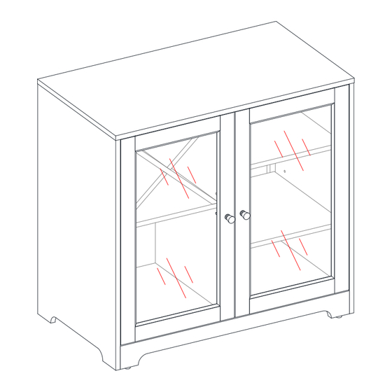
Aster Bar Cabinet
If you have any questions regarding assembly or if parts are missing, DO NOT return this item to the
store where it was purchased. Please call our customer service number and have your instructions
and parts list ready to provide the model name, part name or factory number:
Pacific Standard Time: 8:30 a.m. - 4:30 p.m., Monday - Friday
Or visit our web site 24 hours a day, 7 days a week for product assistance at
THIS INSTRUCTION BOOKLET CONTAINS IMPORTANT SAFETY INFORMATION.
Stock # DJ1346679071107
ADULT ASSEMBLY REQUIRED
www.whalenstyle.com
Or e-mail your request to parts@whalenfurniture.com
PLEASE READ AND KEEP FOR FUTURE REFERENCE.
Date 2023-06-12
1-866-942-5362
Rev. 0001-A
LOT NUMBER:
DATE PURCHASED:
/
/
Advertisement
Table of Contents

Related Manuals for Better Homes and Gardens Dave & Jenny Aster DJ1346679071107


Summary of Contents for Better Homes and Gardens Dave & Jenny Aster DJ1346679071107
- Page 1 LOT NUMBER: DATE PURCHASED: Aster Bar Cabinet Stock # DJ1346679071107 ADULT ASSEMBLY REQUIRED If you have any questions regarding assembly or if parts are missing, DO NOT return this item to the store where it was purchased. Please call our customer service number and have your instructions and parts list ready to provide the model name, part name or factory number: 1-866-942-5362 Pacific Standard Time: 8:30 a.m.
-
Page 2: Special Note
M A X I M U M R E C O M M E N D E D W E I G H T L O A D S MANUFACTURER: Whalen Furniture Manufacturing CATALOG: Aster Bar Cabinet MODEL # DJ1346679071107 MAXIMUM LOAD 90.7 kg / 200 lb MAXIMUM LOAD 22.7 kg / 50 lb MAXIMUM LOAD 4.5 kg / 10 lb... - Page 3 IMPORTANT Before you begin: Open, identify and count all parts prior to assembly. Lay out parts on a flat and non-abrasive surface. You will need the parts identified on page 4 and 5 of this instruction manuals. NOTE: IT IS VERY IMPORTANT TO USE GLUE WITH DOWELS. EXCESS GLUE CAN BE WIPED OFF WITH DAMP CLOTH.
- Page 4 Parts and Hardware List Please read completely through the instructions and verify that all listed parts and hardware are present before beginning assembly. A- Top Panel B- Bottom Frame C- Left Side Panel (Qty. 1) (Qty. 1) (Qty. 1) D- Right Side Panel E- Partition Panel F- Left Door with Nameplate (Qty.
- Page 5 Parts and Hardware List Please read completely through the instructions and verify that all listed parts and hardware are present before beginning assembly. (1) Cam Lock (2) Cam Bolt (3) 1/4” x 32 mm Bolt (Qty. 4+1 extra) (Qty. 4+1 extra) (Qty.
- Page 6 Assembly Instructions ② x 4 NOTE: Please do not fully tighten all screws and bolts until you finish assembling all parts. Once assembled, go back and fully tighten all screws and bolts. This will make the assembly easier. 1. Unpack the unit and confirm that you have all the hardware and required parts. Assemble the unit on a carpeted floor or the empty carton to avoid any scratch.
- Page 7 Assembly Instructions ⑦ x 20 3. Glue twenty Wood Dowels (7) into the designated holes on the Bottom Frame (B), Panels (C, D and E) and Upper Back Stretcher (K). Make sure that you use a small amount of glue with both ends of all dowels.
- Page 8 Assembly Instructions Floor Leveler The notch runs against the back edge of bottom frame. ① x 2 4. Orient and attach the Partition Panel (E) to the Bottom Frame (B) by engaging two Cam Locks (1). (Refer to page 3 on Cam Lock system operation supplement).
- Page 9 Assembly Instructions ③ x 2 ⑥ x 2 ⑤ x 2 5. Align and attach Right Side Panel (D) to the assembled Bottom Frame (B) by inserting two 32 mm Bolts (3) with the Washers (5 and 6) through the cleat and screw into placce.
- Page 10 Assembly Instructions The pilot holes for back panel face backward. ③ x 2 ⑥ x 2 ⑤ x 2 6. Fit the Upper Back Stretcher (K) onto the notch of the Partition Panel (E) and attach it to the back upper corner of Right Side Panel (D) by inserting the end wood dowels.
- Page 11 Assembly Instructions The threaded inserts overlap the mounting holes on the Upper Back Stretcher (K) properly. ① x 2 ③ x 4 ⑥ x 4 ⑤ x 4 8. Using the inserted wood dowels as a guide, place the Top Panel (A) onto the previous assembly properly.
- Page 12 Assembly Instructions ④ x 4 ⑥ x 4 ⑤ x 4 10. Insert four 50 mm Bolts (4) with the Washers (5 and 6) through the mounting holes on the Upper Back Stretcher (K) and securely screw into the Top Panel (A).
- Page 13 Assembly Instructions The adhesive tape faces outward. ⑧ x 20 11. Now, go back and securely tighten all the bolts and screws. Make sure that all the parts are tight and there are no gaps between the parts. This will help keep the unit square. 12.
- Page 14 Assembly Instructions ⑩ x 2 ⑨ x 2 14. Fasten one Knob (9) to the front of each Door (F and G) with one 25 mm Bolt (10).
- Page 15 Assembly Instructions Depth Adjustment Horizontal Adjustment Vertical Adjustment Release leveler “J” hook 15. Ask for assistance to lift the assembled unit upright and position it near the final location. 16. Pick up the Left Door (F) and attach the extended hinge arms to the hinge bases installed on the Left Side Panel (C).
- Page 16 Assembly Instructions I /J x 12 18. Open the doors and insert twelve Shelf Supports (11) into the holes at the desired height inside the vertical panels. Make sure you place four shelf supports at the same level to level the shelf. Tilt and rest the Adjustable Shelves (I and J) onto the Shelf Supports (11).
- Page 17 Assembly Instructions 19. Comebine the Wine Rack Panels (H) together as shown.
- Page 18 Assembly Instructions 20. Place the Wine Rack Assembly (H) onto the Left Adjustable Shelf (I) properly 21. Place the assembled Wine Rack (H) at the left upper compartment, onto the Small Adjustable Shelf (I) properly.
- Page 19 Assembly Instructions 22. Plug the Cam Lock Covers (12) onto the visible cam locks of Partition Panel (E) to conceal the cams.
- Page 20 Assembly Instructions Wooden stud Wall Nylon strap Short screw Wall Long screw Metal bracket Floor leveler Tools required (not included): Phillips screwdriver, stud finder, tape measure, pencil, power drill and 1/8” drill bit. 23. Ask for assistance to position the assembled unit at the desired location against a wall and adjust the Floor Levelers to level the unit.
-
Page 21: Care And Maintenance
Care and Maintenance Use a soft, clean cloth that will not scratch the surface when dusting. Use of furniture polish is not necessary. Should you choose to use polish, test first in an inconspicuous area. Using solvents of any kind on your furniture may damage the finish. ... - Page 23 NÚMERO de LOTE:__________ FECHA de COMPRA: Gabinete bar Aster Modelo # DJ1346679071107 ENSAMBLE REQUERIDO POR ADULTO Si tienen alguna pregunta acerca del ensamble o si alguna parte está faltante, no retorne esté producto a la tienda donde lo compro. Por favor llame a nuestro departamento de ayuda al cliente teniendo su instructivo y lista de partes para proveer el modelo, nombre de parte o el número de fábrica: 1-866-942-5362 Hora estándar del Pacífico: 8:30 a.m.
- Page 24 M Á X I M O P E S O R E C O M E N D A D O FABRICANTE: Whalen Furniture Manufacturing CATALOGO : Gabinete bar Aster MODELO # DJ1346679071107 CARGA MÁXIMA 90.7 kg / 200 lb. CARGA MÁXIMA 22.7 kg / 50 lb.
- Page 25 Importante Antes de comenzar: Abra, identifique y cuente todas las partes antes del ensamble. Coloque las piezas sobre una superficie plana y no abrasiva. Tendrá las partes identificadas en las páginas 4 y 5 de este manual de instrucciones. NOTA: ES MUY IMPORTANTE EL USO DE GOMA CON LAS CLAVIJAS DE MADERA.
- Page 26 Lista de partes y material de ferretería Por favor lea completamente las instrucciones y verifique que estén todas las partes y partes de ferretería antes de iniciar el ensamblado A- Panel superior B- Marco inferior C- Panel izquierdo (Cant. 1) (Cant.
- Page 27 Lista de partes y material de ferretería Por favor lea completamente las instrucciones y verifique que estén todas las partes y partes de ferretería antes de iniciar el ensamblado. (1) Tuerca de fijación (2) Perno de fijación (3) Perno de 1/4 de pulgada x 32 mm (Cant.
- Page 28 Instructivo de ensamble ② x 4 NOTA: Por favor no apriete completamente todos los pernos, hasta que termine con el ensamble de las partes. Después asegúrese de apretar todos los pernos. Esto hará el ensamble más fácil. 1. Desempacar la unidad y confirmar que se tiene todo el material de ferretería y partes requeridas. Ensamblar la unidad en un piso alfombrado o en el cartón vacío para evitar rasguños.
- Page 29 Instructivo de ensamble ⑦ x 20 3. Pegar 20 clavijas de madera (7) en los agujeros designados en el marco inferior (B), en los paneles (C, D y E) y en el soporte superior posterior (K). Asegurar de usar una cantidad pequeña de pegamento en ambos lados de las clavijas.
- Page 30 Instructivo de ensamble Nivelador de piso La muesca corre contra el borde posterior del marco inferior. ① x 2 4. Orientar y adjuntar el panel divisor (E) al marco inferior (B) empleando 2 tuercas de fijación (1). (Consulte la página 3 del sistema de tuerca de fijación).
- Page 31 Instructivo de ensamble ③ x 2 ⑥ x 2 ⑤ x 2 5. Alinear y adjuntar el panel derecho (D) al marco inferior ensamblado (B) insertando 2 pernos de 32 mm (3) con las arandelas (5 y 6) a través del taco y atornillar en su lugar.
- Page 32 Instructivo de ensamble Los agujeros pilotos para el panel posterior apuntan hacia atrás. ③ x 2 ⑥ x 2 ⑤ x 2 6. Encajar el soporte superior posterior (K) sobre la muesca del panel divisor (E) y adjuntar en la esquina posterior superior del panel derecho (D) insertando los extremos de las clavijas de madera.
- Page 33 Instructivo de ensamble Los insertos roscados sobre ponen los agujeros de montaje en el soporte superior posterior (K) apropiadamente. ① x 2 ③ x 4 ⑥ x 4 ⑤ x 4 8. Usando las clavijas de madera insertadas como guía, poner el panel superior (A) sobre el ensamble previo.
- Page 34 Instructivo de ensamble ④ x 4 ⑥ x 4 ⑤ x 4 10. Insertar 4 pernos de 50 mm (4) con las arandelas (5 y 6) a través de los agujeros de montaje en el soporte superior posterior (K) y atornillar en el panel superior (A).
- Page 35 Instructivo de ensamble La cinta adhesiva apunta hacia afuera. ⑧ x 20 11. Ahora, volver y apretar todos los pernos. Asegurar que todas las partes estén apretadas y de que no hay huecos entre las partes. Esto ayudara a mantener la unidad cuadrada. 12.
- Page 36 Instructivo de ensamble ⑩ x 2 ⑨ x 2 14. Sujetar una perilla (9) al frente de cada puerta (F y G) con un perno de 25 mm (10).
- Page 37 Instructivo de ensamble Ajuste de profundidad Ajuste horizontal Ajuste vertical Palanca de liberación Gancho “J” 15. Pedir asistencia para poner la unidad ensamblada en posición vetical y cerca del lugar final. 16. Tomar la puerta izquierda (F) y adjuntar los brazos de bisagra extendidos a las bases de bisagra instaladas en el panel izquierdo (C).
- Page 38 Instructivo de ensamble I /J x 12 18. Abrir las puertas e insertar 12 soportes para repisa (11) en los agujeros a la altura deseada dentro de los paneles verticales. Asegurar de poner 4 soportes para repisa en el mismo nivela para anivelar la repisa. Inclinar y descansar las repisas ajustables (I y J) sobre los soportes para repisa (11).
- Page 39 Instructivo de ensamble 19. Combinar los panel para el vino (H) como se muestra.
- Page 40 Instructivo de ensamble 20. Poner el ensamble del panel para vino (H) sobre la repisa ajustable izquierda (I) apropiadamente. 21. Poner el panel para vino ensamblado (H) en el compartimiento izquierdo superior, sobre la repisa ajustabe pequeña (I) apropiadamente.
- Page 41 Instructivo de ensamble 22. Enchufar las tapas de las tuercas de fijación (12) sobre las tuercas de fijación visisbles del panel divisor (E) para esconder.
- Page 42 Instructivo de ensamble Viga de madera Pared Correa de Nylon Perno corto Pared Perno largo Soporte de metal Nivelador de piso Herramientas requeridas (no incluidas): Desarmador estrella, buscador de vigas, cinta métrica, lápiz, taladro y broca de 1/8 de pulgada. 23.
-
Page 43: Mantenimiento Y Cuidados
Mantenimiento y Cuidados Use una toalla suave y limpia para evitar daños y rayaduras. Uso de cera para pulir muebles no es necesario. Si desea usar cera, pruébela en un área que no sea visible para revisar su funcionamiento. ...
Need help?
Do you have a question about the Dave & Jenny Aster DJ1346679071107 and is the answer not in the manual?
Questions and answers