
Related Manuals for TSI Instruments AIRASSURE 8144


Summary of Contents for TSI Instruments AIRASSURE 8144
- Page 1 AIRASSURE ™ INDOOR AIR QUALITY MONITOR MODEL 8144 OPERATION AND MAINTENANCE MANUAL P/N 6015658, REVISION C JUNE 2021...
- Page 3 Copyright© TSI Incorporated / 2021 / All rights reserved. Part Number 6015658 / Revision C / June 2021 Address TSI Incorporated / 500 Cardigan Road / Shoreview, MN 55126 / USA Fax No. (651) 490-3824 LIMITATION OF WARRANTY AND LIABILITY (effective February 2020) (For country-specific terms and conditions outside of the USA, please visit www.tsi.com.) Seller warrants the goods, excluding software, sold hereunder, under normal use and service as described in the operator's manual, to be free from defects in...
- Page 4 BUYER’S EXCLUSIVE REMEDY SHALL BE THE RETURN OF THE PURCHASE PRICE DISCOUNTED FOR REASONABLE WEAR AND TEAR OR AT SELLER’S OPTION REPLACEMENT OF THE GOODS WITH NON-INFRINGING GOODS. TO THE EXTENT PERMITTED BY LAW, THE EXCLUSIVE REMEDY OF THE USER OR BUYER, AND THE LIMIT OF SELLER'S LIABILITY FOR ANY AND ALL LOSSES, INJURIES, OR DAMAGES CONCERNING THE GOODS (INCLUDING CLAIMS BASED ON CONTRACT, NEGLIGENCE, TORT, STRICT LIABILITY OR OTHE RWISE)
-
Page 5: Table Of Contents
Conte nts Safety Inform ation....................v Description of Caution/Warning Sy mbols ............v Caution ....................v Warning ....................v Caution and Warning Sy mbols ..............v Laser Safety ....................vii Labels ......................viii Reusing and Recycling ................viii Chapter 1 Product Overview ................1 Unpacking .....................2 AirAssure™... - Page 6 (This page intentionally left blank)
-
Page 7: Safety Inform Ation
Safe ty Inform ation Description of Caution/Warning Symbols Appropriate caution/warning statements are used throughout the manual and on the instrument that require you to take cautionary measures when working with the instrument. Caution C AU T I O N Failure to follow the procedures prescribed in this manual might result in irreparable equipment damage. - Page 8 WAR N I N G • Use of components other than those specified by ® ® Incorporated (TSI ) may impair the safety features provided by the equipment. • When mains power adapters are used, the equipment should be positioned so the mains plug will remain accessible for emergency disconnect.
-
Page 9: Laser Safety
Laser Safety • AirAssure™ Indoor Air • You will not be exposed to Quality monitors are Class 1 the laser radiation when the AirAssure™ IAQ monitor is laser-based instruments. disassembled. • During normal operation, • The PM sensor has a laser you will not be exposed to laser radiation. -
Page 10: Labels
Labels Advisory labels and identification labels are attached to the instrument. 1. Serial Number Label (back) 2. Laser Radiation Label (internal, on the PM sensor) Safety Details FCC ID: 2AC7Z-ESPWROV ERE Contains IC ID: 2AC7Z-ESPWROV ERE 4. European symbol for non-disposable item. -
Page 11: Chapter 1 Product Overview
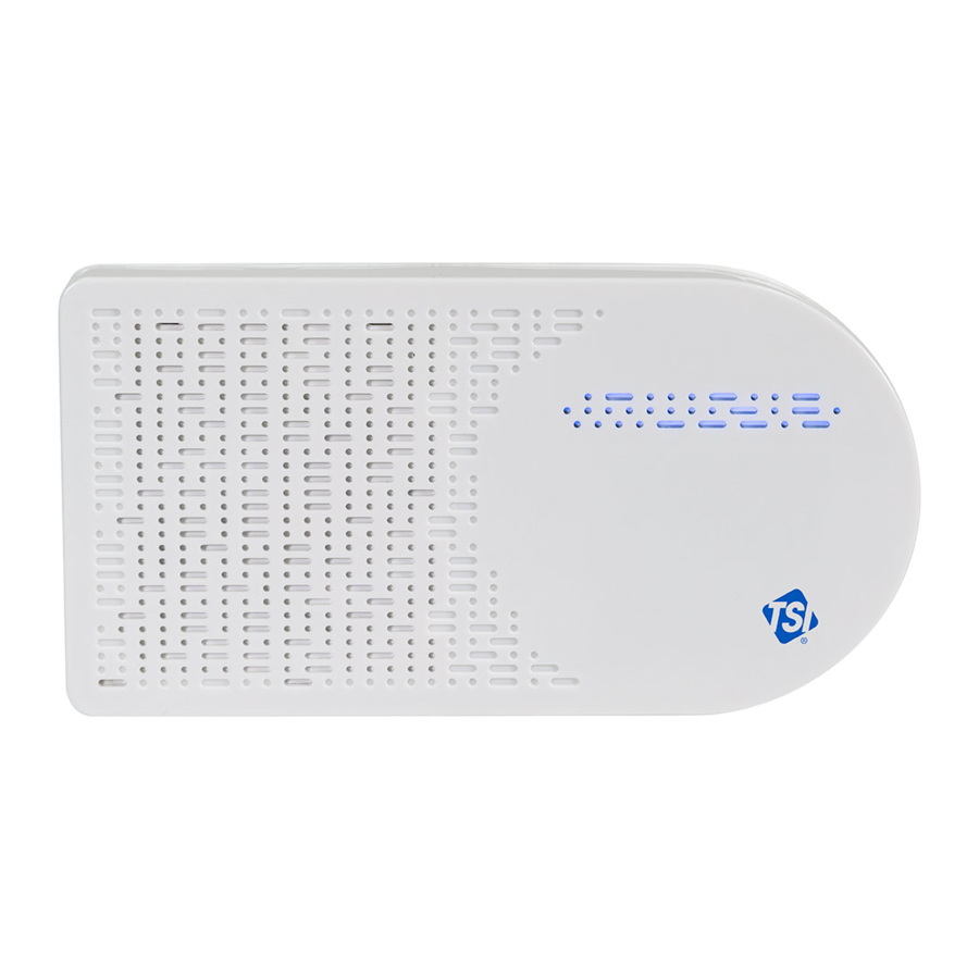
Chapter 1 Product Ov e rv iew Incorporated’s AirAssure™ Indoor Air Quality Monitor is a ® real-time Particulate Matter (PM) and Gas monitor designed to provide accurate gas and mass concentrations as well as temperature, humidity, and barometric pressure measurements. The monitor is designed to be deployed in less than ten minutes and is intended for indoor air quality monitoring only. -
Page 12: Unpacking
Unpacking Compare all the components you received with those listed in the table below. Item Description AirAssure™ Indoor Air Quality Monitor USB Power Supply Country Specific Plug Adapter Kit 2m USB-A to USB-C Cable 24 VAC Terminal Connector 32 GB microSD card (installed) Mounting Kit: (2 screw and plug sets,... -
Page 13: Airassure™ Iaq Monitor Replacement Parts
AirAssure™ IAQ Monitor Replacement Parts Listed below are replacement items for the AirAssure™ Indoor Air ® Quality Monitor. Contact for purchase information. Part Number Item Description Replacement 4-Gas Variant Sensor Cartridge: CO, 814401 tVOC, Temperature, Relative Humidity, and Barometric Pressure Replacement 6-Gas Variant Sensor Cartridge: CO, O... - Page 14 Part Number Item Description Replacement 814406 Power Supply Kit Replacement 814407 Membrane Filters (pack of 3) Chapter 1...
-
Page 15: Chapter 2 Setting Up
Chapter 2 Se tting Up The AirAssure™ Indoor Air Quality Monitor is delivered fully assembled and ready to be mounted on an interior wall. Start by unpacking the device and its contents from the shipping package. ® The monitor is intended to be connected to local 2.4 GHz Wi-Fi ®... -
Page 16: Create An Account Tsi Link™ Solutions For Cloud Features
NOTE The monitor does not have the capability to connect to public ® Wi-Fi networks that require a second step of browser authentication, such as a free public hotel or airport network. A different network will need to be chosen. NOTE Some corporate networks require the device MAC address for security. -
Page 17: Connecting The Airassure™ Iaq Monitor To A Wi-Fi ® Network
3. Enter the serial number from the back of your device. 4. Enter other information. 814462021001 Connecting the AirAssure™ IAQ Monitor to a ® Wi-Fi Network For best results, set up the device before mounting it in a permanent location. However, ensure you have good Wi-Fi ®... - Page 18 It can be mounted using screws or using double-sided tape (included). 1. Remove the power supply, plug adapter kit, and USB-C cable from its packaging. Select your region’s plug connector and mate it to the power supply by “snapping” the plug connector into the adapter.
- Page 19 4. The monitor should turn on as indicated by the light bar on the front. To connect the monitor to the internet, you first have to connect to the monitor’s hot spot. 5. Pulse yellow indicates that the monitor is in set up mode as a ®...
- Page 20 7. With your phone camera, scan the QR code at the top of the label to connect to the monitor’s Wi-Fi ® hotspot. You should be ® prompted to connect to a new Wi-Fi network called “AirAssure IAQ 8144XXX…” 8. If you are not connected automatically, you can still connect ®...
- Page 21 9. Once connected to the AirAssure™ IAQ monitor Wi-Fi ® network, use your phone camera again to connect to the setup web page or open your phone browser and enter a URL of 192.168.4.1. 10. You should see a web page like the one below. Select your home ®...
- Page 22 ® 11. Enter the local Wi-Fi password and click Save. 12. The monitor should automatically power cycle and start again with a pulsing yellow LED light bar. 13. The process of connecting to your local internet will be reflected in the color sequence shown below. This may take several minutes.
- Page 23 14. If all connections are made, the LED will be solid blue. 15. You can then connect to your device through TSI Link™ Solutions at www.tsi.com/tsilink. 16. If the LED light bar stops at solid white, review the steps above and repeat as needed or see the “Getting Help”...
-
Page 24: Installing The Airassure™ Indoor Air Quality Monitor
Installing the AirAssure™ Indoor Air Quality Monitor The AirAssure™ IAQ monitor can be mounted using screws or using ® ® double-sided tape (such as 3M Command strips). Power can be supplied using either a wall plug or building-supplied 24 VAC from inside a wall. - Page 25 3. If using screws, position the template from the quick start guide and use the included level to mark the screw locations on the wall for mounting. If using a wall plug, install the screws and mount the monitor. 4. If using 24 VAC power, mark the cut-out guide area for the wiring feed through (large circle or rectangle).
- Page 26 6. Before applying power to the connection, insert the 24 VAC plug into back of monitor and mount it on the wall. 7. If the screws need to be more secure, press gently on the two pads on top of the front cover and push down and away from the wall.
- Page 27 9. When power is now applied, the light bar on the monitor will illuminate and pulse yellow. 10. The process of connecting to your local internet will be reflected in the color sequence shown below. This may take several minutes. The LED light bar should be solid blue. Cloud ®...
-
Page 28: Getting Help
Getting Help There is a wealth of support material available online. Please check the Help Center at: www.tsi.com/tsilink. Chapter 2... -
Page 29: Chapter 3 Operation
Chapter 3 Ope ration Overview The AirAssure™ Indoor Air Quality (IAQ) Monitor’s primary use is for indoor applications. It is designed to operate 24/7 when powered by a power outlet or 24 Volts AC low-voltage building power. Once you have setup your monitor(s) and connected them to a local wireless ®... - Page 30 5. You will receive an e-mail from TSI Link™ Solutions to verify your e-mail address. Once you receive this e-mail click on the Verify Link. 6. Go back to the web browser and click DONE on the AirAssure™ IAQ monitor screen. Chapter 3...
- Page 31 7. Wait for the 10-second count down then log in with your new online AirAssure™ IAQ monitor login credential. 8. Register your device by entering in the required information and click DONE. If you do not see the Device Registration screen, click the “Plus”...
-
Page 32: How To View Data From One Or More Airassure™ Iaq Monitors
10. When the device is connected and running, verify your device pin is displaying current measurements to confirm you successfully signed up for an online account and registered your device. How to View Data from one or more AirAssure™ IAQ Monitors 1. -
Page 33: How To Download Data From One Or More Airassure™ Iaq Monitors
How to Download Data from one or more AirAssure™ IAQ Monitors 1. Go to www.tsi.com/tsilink and log in. 2. Click on the map and zoom in to the area where your AirAssure™ IAQ device pin is located. 3. Click on the device pin. 4. -
Page 34: Interpreting The Data Downloaded From The Microsd Card Or From The Cloud
Interpreting the Data Downloaded from the microSD Card or from the Cloud Data downloaded from the AirAssure™ Indoor Air Quality Monitor from the microSD card or cloud is stored as an ASCII format file with the serial number and date as the filename and .csv as the extension (e.g. - Page 35 Chapter 4 Mainte nance ® Replacement sensors can be ordered from TSI Incorporated. Although sensor life times vary depending on the conditions they are exposed to, conservative recommended replacement intervals are listed below for each sensor: NOTE Recommend replacement intervals are derived from the expected indoor conditions: Temperature (65 to 75°F/18 to 24°C) and Relative Humidity (30 to 50%).
- Page 36 Recom m ended Part Replacem ent Item Description Num ber Interval ® Calibrated 814403 3 years PM Replacement Sensor Replacement 814404 3 years Sensor Formaldehyde 814405 1 year Replacement Sensor 1. Any maintenance should be performed only after powering the unit down by disconnecting the USB cable from the power adapter or removing the unit from the wall and disconnecting the 24 VAC power connector from the back panel.
-
Page 37: Chapter 4 Maintenance
3. You can identify the sensors based on the table above and picture below. Detailed directions follow for each sensor. Replacing the Multi-Sensor Cartridge and Membrane 1. Release the lever at the bottom-left of the board and lift the bottom of the PC board slightly away from the back panel. 2. -
Page 38: Replacing The Pm Sensor
Replacing the PM Sensor 1. Unplug the connector on the left by pressing the locking clips in from the top and bottom and pulling the connector straight out. 2. Pull the sensor module from the top and pivot it away from the PC board. -
Page 39: Replacing The Formaldehyde Sensor
Replacing the Formaldehyde Sensor 1. The formaldehyde sensor is located on the left side of the monitor on a separate PC-board. 2. Depress the back of the cable connector (pushing into the page in the picture below). 3. Pull the connector from the top and up. Maintenance... - Page 40 4. Pull the sensor module PC-board from the top and straight away from the wall. You may have to wiggle it up and down to release. 5. Reverse the steps for the new sensor. 6. Replace the cover, power up the monitor and connect it to the cloud to register the new sensor and its calibration values.
-
Page 41: Chapter 5 Troubleshooting The Airassure™ Indoor Air Quality Monitor
Chapter 5 Trouble shooting the AirAssure ™ Indoor Air Quality Monitor Detailed troubleshooting and frequently asked questions can be found at www.tsi.com/tsilink. The table below lists some symptoms, possible causes, and recommended solutions for common problems encountered with the AirAssure™ Indoor Air Quality Monitor. Possible Cause Corrective Action The AirAssure™... - Page 42 Possible Cause Corrective Action Cannot connect to Note that AirAssure™ IAQ monitor can only connect ® ® ® Wi-Fi or the to 2.4 GHz Wi-Fi signals. Most Wi-Fi routers provide several frequency channels. Please make internet. sure you are connecting to the 2.4 GHz channel. The monitor does not have the capability to connect to public netw orks that require a second step of brow ser authentication, such as a free public hotel or...
-
Page 43: Appendix A Specifications
Appendix A Spe cifications* Overall Operating Temp Range ... 0 to 40ºC (32 to 104ºF) Operating Humidity Range..15 to 95% non-condensing Storage Temperature....5 to 30ºC (41 to 86ºF) Case Dimensions ..... 171 mm x 89 mm x 33 mm 6.75 in. - Page 44 Gas Sensors (if installed) Range ........ 0 to 5 ppm Resolution ......1 ppb Temperature Sensor Range......... -40 to 125°C (-40 to 257ºF) Accuracy ........±0.5°C (±32.9°F) Humidity Sensor Range......... 0 to 100% RH Accuracy ........±3% RH Barometric Pressure Sensor Range.........
- Page 46 TSI Incorporated – Visit our website www.tsi.com for more information. Tel: +1 800 680 1220 India Tel: +91 80 67877200 Tel: +44 149 4 459200 China Tel: +86 10 8219 7688 France Tel: +33 1 41 19 21 99 Singapore Tel: +65 6595 6388 Germany Tel: +49 241 523030 P/N 6015658 Rev.
Need help?
Do you have a question about the AIRASSURE 8144 and is the answer not in the manual?
Questions and answers