Table of Contents
Advertisement
Quick Links
Advertisement
Table of Contents

Subscribe to Our Youtube Channel
Related Manuals for Burkert 6030 Series


Summary of Contents for Burkert 6030 Series
- Page 1 Type 6030 2/2-way solenoid valve Operating Instructions...
- Page 2 We reserve the right to make technical changes without notice. © Bürkert Werke GmbH & Co. KG, 2024 Operating Instructions 2407/00_EUen_ 00815473 / Original EN...
-
Page 3: Table Of Contents
Type 6030 Table of Contents TABLE OF CONTENTS 1 About this document.......................... 4 Manufacturer............................. 4 Symbols ............................ 4 Terms and abbreviations ........................ 5 2 Safety ................................ 6 Intended use ............................. 6 Safety instructions .......................... 6 3 Product description ........................... 9 Product structure .......................... 9 Type label............................ 10 4 Technical data ............................ 11 Standards and directives ........................ 11 Operating conditions........................ 11 Circuit function.......................... 12... -
Page 4: About This Document
Before starting any work on the product, read and observe the respective sections of the document. Keep the document available for reference and give it to the next user. Contact the Bürkert sales office for any questions. Further information concerning the product at country.burkert.com. Manufacturer Bürkert Fluid Control Systems Christian-Bürkert-Str. -
Page 5: Terms And Abbreviations
Type 6030 About this document Terms and abbreviations The terms and abbreviations are used in this document to refer to following definitions. Device 2/2-way solenoid valve, Type 6030... -
Page 6: Safety
Type 6030 Safety SAFETY Intended use The device is designed to control the flow rate of media. The permitted media are listed in Technical data [} 11]. Prerequisites for safe and trouble-free operation are correct proper transportation, storage, installation, start-up, operation and maintenance. The instructions are part of the device. - Page 7 Type 6030 Safety Spare parts and accessories that do not meet Bürkert’s requirements may impair the operational safety of the device and cause accidents. To ensure operational safety, only use original parts from Bürkert. Operation only after proper transport, storage, installation, start-up or maintenance. Improper transport, storage, installation, start-up or maintenance endanger the operational safety of the device and can cause accidents.
- Page 8 Type 6030 Safety Risk of injury from malfunctioning valves with alternating current (AC) If the core sticks, the solenoid will overheat and cause the valve to malfunction. Monitor valve function.
-
Page 9: Product Description
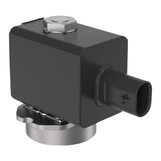
Type 6030 Product description PRODUCT DESCRIPTION Type 6030 is a compact 2/2-way solenoid valve with the following properties: Vibration-proof, screwed coil system. Increased leak proofing through welded core guide tube. Available as a flange or plush-in flange variant for fast system integration. Degree of protection IP65 or IP6K9K with automotive plug. -
Page 10: Type Label
Type 6030 Product description Fig. 3: Type 6030 socket variants GM81/GM82 1 Coil 2 Valve body 3 Type label 4 Nut for coil attachment Type label Fig. 4: Type 6030 type label (example) 1 Type 2 Circuit function 3 Orifice 4 Sealing material 5 Body material 6 Operating pressure 7 Cold power (tolerance ±10%) -
Page 11: Technical Data
Type 6030 Technical data TECHNICAL DATA Standards and directives The device complies with the valid EU harmonisation legislation. The harmonised standards that have been applied for the conformity assessment procedure are listed in the current version of the EU Declaration of Conformity. Operating conditions Medium neutral gases and liquids, optimised for hydrogen... -
Page 12: Circuit Function
Type 6030 Technical data Circuit function Icon Description 2 (A) Circuit function A (CF A), NC 2/2-way solenoid valve, direct-acting 1 (P) Normally closed Tab. 2: Circuit function... -
Page 13: Installation
Type 6030 Installation INSTALLATION Risk of injury or material damage when working on the device or system. Read and observe the chapter Safety [} 6] before working on the device or system. Preparatory work DANGER! Risk of injury from high pressure and discharge of medium. Before working on the device or system, switch off the pressure. - Page 14 Type 6030 Installation NOTICE! Ensure that the O-rings on the valve body and the seal surfaces of the connection housing are not dam- aged during installation. Variant Nominal diameter DN Tightening torques [Nm] Screw FC22 1…3 M4 x 15 A2 8.8 (screws not included in the scope of delivery) FC23...
- Page 15 Type 6030 Installation M4 10 Fig. 7: Connection diagram 2 for plug-in flange variant FC22 45 +0,1 Rmax 6,3 35,5 0,05 Fig. 8: Connection diagram 1 for plug-in flange variant FC23 M4 10 Fig. 9: Connection diagram 2 for plug-in flange variant FC23...
-
Page 16: Flange Variant Installation
Type 6030 Installation Flange variant installation Fig. 10: Flange variant installation Ensure that the O-rings on the valve body and the seal surfaces of the connection housing are free of any damage. Place the valve on the connection housing. Tightly screw in the valve body, observing the tightening torque indicated in the following table. NOTICE! Ensure that the O-rings on the valve body and the seal surfaces of the connection housing are not dam- aged during installation. -
Page 17: Installation Of Socket Variants
Type 6030 Installation deep M4 10 Fig. 11: Connection diagram for flange variant FK18 and FK19 Installation of socket variants Fig. 12: Installation of socket variants Note the flow direction: from 1 to 2 (from P to A). Ensure that the seal surfaces on the port connections are free of any damage. Hold the device on the valve body using an open-end wrench and screw into the pipe. - Page 18 Type 6030 Installation CAUTION! Risk of injury from electric shock If there is no protective conductor function between the coil and the body, there is a risk of electric shock. The anti-twist device (plastic ring) must be inserted into the body pins during installation. It must not protrude over the octagonal nipple.
-
Page 19: Cable Plug Installation
Type 6030 Installation Variant Nominal diameter DN Tightening torque [Nm] all variants 1…3 4…6 Tab. 5: Coil installation Cable plug installation CAUTION! If there is no protective conductor function, there is a risk of injury from electric shock. Always connect the protective conductor. Check electrical continuity between coil and body. -
Page 20: Electrical Connection
Cable plug Permitted variants of the cable plug and further information such as wiring and electrical character- istics are available in the data sheet for Type 6030 at country.burkert.com. Automotive plugs for IP6K9K coil variants For mobile applications, coils are provided with the following automotive plugs: KOSTAL MLK1.2 plug, 2-pin, A-coded (male) -
Page 21: Faults
Type 6030 Faults FAULTS Risk of injury or material damage when working on the device or system. Read and observe the chapter Safety [} 6] before working on the device or system. DANGER! Risk of injury from high pressure and discharge of medium. Before working on the device or system, switch off the pressure. -
Page 22: Logistics
Protect connections from damage with protective caps. Observe permitted storage temperature. Disposal Environmentally friendly disposal Follow national regulations regarding disposal and the environment. Collect electrical and electronic devices separately and dispose of them as special waste. Further information at country.burkert.com...
Need help?
Do you have a question about the 6030 Series and is the answer not in the manual?
Questions and answers