Table of Contents
Advertisement
Quick Links
Advertisement
Table of Contents

Related Manuals for Johnson JR8 SLT Series


Summary of Contents for Johnson JR8 SLT Series
-
Page 3: Acerca De La Documentación
Acerca de la documentación Destinatarios Instaladores autorizados + usuarios finales Documentación Este documento forma parte de un conjunto de documentación. El conjunto completo consta de: Datos técnicos de ingeniería La documentación original está escrita en inglés. Todos los demás idiomas son traducciones. - Page 4 Lea detenidamente y asegúrese de que entiende completamente las precauciones de seguridad (incluidos los signos y lesiones graves. provocar lesiones graves. lesiones leves o moderadas. el riesgo de incendio. servicio técnico con referencia al manual de instalación. instrucciones o el manual de instalación.
-
Page 6: Advertencia De Seguridad
Advertencia de seguridad Solo profesionales Garantizar una conexión a tierra adecuada No colocar Sin materiales Sin corrientes fuertes Sin llamas abiertas; cosas inflamables prohibido encender fuego, ácidos ni alcalinos fuentes de ignición abiertas y fumar 2.5m... - Page 9 • Purgar el circuito con gas inerte.
- Page 10 equipo sin demora y de cerrar todas las válvulas de aislamiento del equipo.
- Page 11 Funcionamiento...
- Page 13 condición. segura y eficaz. Temperatura 16~32 °C interior Humedad interior Temperatura Calefacción 15~30 °C interior puede no funcionar. Protección normal del aparato de aire acondicionado justo antes. de calor se calienta para evitar el soplado de aire frío. una vez finalizada la descongelación. funciona utilizando la función Protección antiaire frío.
- Page 14 ángulo de la rejilla y la velocidad del ventilador para prevenir la condensación y evitar el goteo. Los siguientes síntomas no son fallos del sistema Los siguientes fenómenos son normales durante el funcionamiento del aparato de aire acondicionado. • • La unidad interior expulsa polvo La unidad interior emite olor acondicionado y lo sometan a mantenimiento con regularidad.
- Page 15 el funcionamiento de la refrigeración o la calefacción. • • Conflicto de modos Todas las unidades interiores de un mismo sistema de refrigerante solo pueden funcionar en el funcionan en el mismo modo.
- Page 16 controlador remoto. Los componentes y accesorios de las unidades no forman parte de los residuos domésticos ordinarios. cualificados.
-
Page 17: Instalación
Instalación Lea atentamente este manual antes de instalar la unidad interior. aire acondicionado. Productos designados del aparato de aire acondicionado es seguro y no suelen producirse fugas. unidades de calefacción del calefactor/estufa eléctrica/cocina. Desconecte el suministro eléctrico del aparato de la sala para permitir la ventilación y asegurarse de que la concentración de fuga de refrigerante en la sala o con personal profesional. - Page 18 instalación. eléctricos y la moqueta. incendio.
- Page 19 de instalación. especificado en la placa de características. el rendimiento del aparato de aire acondicionado o provocando fugas de agua. diluyentes o gasolina. Los componentes electrónicos del aparato de aire acondicionado pueden provocar la ignición del gas circundante. El sistema de control fallará y el aparato de aire acondicionado no funcionará correctamente. No utilice el aire acondicionado en un entorno en el que pueda producirse una explosión.
- Page 20 Elija un lugar que cumpla totalmente los siguientes requisitos del usuario y condiciones para instalar la unidad de aire acondicionado: Hay espacio suficiente para la instalación y el mantenimiento. Es fácil suministrar flujo de aire a todos los rincones de la sala. Evite instalar la unidad en espacios reducidos o donde los requisitos acústicos sean más estrictos.
- Page 21 Esquema de instalación Panel de visualización Lama superior e inferior tierra Todas las figuras del manual explican únicamente el aspecto general y las funciones del producto. El aspecto y las funciones del producto adquirido pueden no coincidir totalmente con los que aparecen en las figuras. Consulte el producto real.
- Page 22 Tubería de gas (F) Tubería de Tubería de líquido (H) 1069 1284 1199 1649 1565...
- Page 23 Tubería de líquido Tubería de gas Salida trasera derecha Salida inferior derecha...
- Page 24 Agujeros circulares Agujeros circulares Parte trasera derecha Parte inferior derecha Lista de accesorios Manual de instalación y funcionamiento X 1 térmico X 2 (asegúrese de de agua no disponen de evitar la condensación de conexión este accesorio a la salida de en las conexiones de Pernos de elevación X 4 la unidad...
- Page 25 Lado del líquido Lado del gas Potencia longitud seleccionada de acuerdo con la situación real. de 25 mm de diámetro. La longitud se determina en función de las necesidades reales. grosor. Los materiales necesarios para la instalación normas locales o industriales correspondientes. estanqueidad.
- Page 26 El punto rojo sobresale Sellado unidad. El punto rojo se retrae Fuga de aire refrigerante adicional.
- Page 27 suelo. ≥ Manguito Exterior Tubería de conexión Manguito aislante Dirección de paso recomendada Interior No deje que la interfaz de la unidad interior materiales de aislamiento térmico podrían y condensación. exteriores.
- Page 28 romperse fácilmente. MPa mediante una válvula limitadora de presión. fosforado que no requiera fundente. Válvula reductora de presión Posición de Tubería de soldadura refrigerante Envoltura Nitrógeno Válvula manual Cortatubos 90°±4 Diámetro exterior Máx. Mín. R0.4–0.8...
- Page 29 Barra Barra Abrazadera Cono Tubería de conexión Asa de abrazadera Marca de flecha roja muestra en la figura. La soldadura se realiza Aplicar aceite refrigerante a las superficies interior y exterior Tuerca de la toma de la tubería. abocardada Llave dinamométrica Tuerca de protección Tubería de la Tuerca abocardada...
- Page 30 adecuado. Diámetro exterior de la 20~40 Unidad exterior Unidad interior Válvula Conecte la unidad de aspiración de cierre mediante un colector al puerto de servicio de todas las válvulas de cierre. Manómetro de alta presión Válvula de bombeo Manómetro de baja presión Bomba de vacío...
- Page 31 Detección de fugas minuto. tenga fugas. Descargue todo el gas nitrógeno. la presión manométrica por encima de la presión máxima de funcionamiento de la Tratamiento de aislamiento térmico suficientes medidas de aislamiento para evitar la condensación. de gas. El material aislante fijado para la parte de la unidad interior Los materiales de aislamiento térmico expuestos directamente in situ estructuras metálicas para conductos.
- Page 32 compresor podría quemarse. provocar condensación y fugas de agua. a 120 °C. 4. Grosor de la capa aislante de la capa aislante es superior a 15 mm. de la capa aislante es superior a 20 mm. 5. Consejos de instalación y aislamiento materiales aislantes ya conectados.
- Page 33 Aquí no quedará ningún hueco Unidad y despegarse con el tiempo. y aplique cola en la junta. Consejos para reparar la capa aislante:...
- Page 34 No conectada Espacio consecuencia derivada del incumplimiento de las instrucciones. inadecuado provocará un deficiente. evitar la condensación. átelas con una...
- Page 35 Tubería de salida de agua de la unidad interior Tubería de del paquete de accesorios • Método para descargar el agua con la salida de natural: Descarga de aire La tubería está dirigida hacia abajo para evitar la entrada de cuerpos extraños.
- Page 36 Tubería de Tubería de PVC Bajada Hacia abajo (diámetro interior de 15 mm) o tubería de PVC rígido (VP-16)* Utilizar adhesivos de PVC El extremo de la Hacia arriba Acumulaciones de agua tubería de está sumergido en agua Aire Fugas Fugas Fugas de agua...
- Page 37 a un tratamiento de aislamiento térmico. Porción alargada de la tubería de Tubería de de la unidad interior Carcasa aislante (comprada localmente) Tubería de salida de agua de la unidad interior Aislamiento de la tubería de agua Tubería de en la parte superior.
- Page 38 fuerza. Asegurarse de que no se salpica agua. con agua.
- Page 39 terminales.
- Page 40 (kW) (Hz) 0.20 0.16 0.28 0.22 0.43 0.34 0.45 0.36 0.60 0.48 220~240 0.75 0.60 0.63 0.50 10.0 0.75 0.60 11.2 1.00 0.80 12.5 1.25 1.00 14.0 garantizar un funcionamiento seguro durante un periodo prolongado de tiempo.
- Page 41 CN22 CN10 CN18 CN55 Terminales de la señal de Módulo de conmutación M1 M2 X1 X2 D1(X) D2(Y) conmutación remota Terminales de comunicación T2 T2B Cubierta de caja de control eléctrico Tornillo (tres)
- Page 42 El terminal de alimentación de la unidad interior está fijado como se muestra en la figura siguiente. como se muestra en la figura siguiente. Manguito aislante Conectar cables del mismo diámetro en ambos lados. Bloque de terminales circular Cable de alimentación No conectar cables del No conectar cables...
- Page 43 Suministro eléctrico de la unidad interior ×× Cables de comunicación Disyuntor Cable de alimentación Caja de distribución Caja de distribución Unidad interior n.º 1 Unidad interior n.º (n-1) Unidad interior n.º n CN22 ··· Unidad interior n.º 2-(n-2) Suministro eléctrico de la unidad interior ××...
- Page 44 interior puede controlarse de forma independiente. disyuntor. Método de comunicación opcional entre las Tipo de unidad interior unidades interiores y la unidad exterior Todas las unidades alimentación uniforme. interiores del sistema conectados en serie. uniforme. interiores del sistema no conectados en serie. no polares.
- Page 45 Comunicación de un Comunicación de controlador a una uno a varios Comunicación entre la unidad exterior y la unidad interior unidad interior (de (controlador dos controladores a una unidad Comunicación Comunicación Comunicación Comunicación Elemento X1X2 D1D2 alimentación de alimentación de Diámetro Longitud 1200 m...
- Page 46 Comunicación entre la unidad interior y la unidad exterior entre electrodos negativos y positivos. Conecte la capa a la figura: Suministro eléctrico de la unidad interior ×× Cables de comunicación Disyuntor Cable de alimentación Caja de distribución Caja de distribución Unidad interior n.º...
- Page 47 P Q E Suministro eléctrico de la unidad interior × × Disyuntor Caja de distribución Caja de distribución Unidad interior n.º 1 Unidad interior n.º (n-1) Unidad interior n.º n CN22 ··· Unidad interior n.º 2-(n-2) L1+La+Ln ≤ 1200 m...
- Page 48 de manera uniforme. entre la unidad interior y la unidad exterior puede verse afectada. X1X2 X1X2 L1 ≤ 200 m, L2+L3 ≤ 200m.
- Page 49 La comunicación D1D2 es una comunicación 485. Las funciones de uno a varios y de dos a varios del se muestra en la siguiente figura: Unidad interior n.º 2 Unidad interior n.º 16 Unidad interior n.º 1 D1 D2 D1 D2 D1 D2 X1 X2 X1 X2...
- Page 50 Conexión de placas externas (limitada a la unidad exterior y a la configuración del Conexión de la caja de visualización CN30 Placa de Caja de control visualización principal Conexión del módulo de conmutación Las placas de expansión pueden comunicarse con la placa de control principal mediante la placa de CN18 CN18 CN10...
- Page 51 Placa de CN22 control principal más información. Control de encendido/apagado remotos Consulte la siguiente figura para utilizar el control remoto de CN55 encendido/apagado. Interruptor remoto Encendido Encendido...
- Page 52 Código de Pantalla Definición error digital Parada de emergencia que requieren parada inmediata Conflicto de modos Código de dirección de la unidad interior duplicado...
- Page 53 Código de Pantalla Error error digital Comunicación anormal entre la unidad interior y la unidad exterior Comunicación anormal entre la placa de control principal de la unidad interior y la placa del impulsor del ventilador Comunicación anormal entre la unidad interior y el kit wifi Comunicación anormal entre la placa de control principal de la unidad interior y la placa de visualización unidad interior maestra...
- Page 54 Código de Pantalla Error error digital cortocircuita o se corta corta corta cortocircuita o se corta se corta cortocircuita o se corta Código de modelo de unidad no ajustado Código de dirección no detectado...
- Page 55 Código de Pantalla Error error digital Error de sesgo de muestreo de corriente de fase El motor y la unidad interior están desparejados El IPM y la unidad interior están desparejados Error de ajuste del modo de control de velocidad Protección ante falta de fase del motor Pantalla Definición...
- Page 56 la función de inspección aleatoria en los siguientes pasos: dirección de la unidad interior n00-n74 (que indica consulta de parámetros. parámetros; los parámetros pueden consultarse consulte la lista de inspección aleatoria que figura a continuación. consulta. parámetros de la inspección aleatoria. Contenido visualizado Contenido visualizado Dirección de la unidad interior...
- Page 57 No encienda el sistema. Lea todo el Manual de instalación y funcionamiento. Instalación Compresor y otros soportes de envío retirados. gas. aisladas según sea necesario. Entrada/salida de aire cualquier otro material. tierra. de componentes eléctricos y dentro de la unidad.
- Page 58 las unidades interior y exterior pertenecen al mismo sistema de refrigeración. agente local. Puede causar congelación. refrigerante. de la fuga. componentes del sistema. • • son normales. • El indicador LED está encendido. • El vaciado del agua es normal. •...
-
Page 59: Mantenimiento Y Servicio Técnico
Mantenimiento y servicio técnico un incendio. polvo del aire interior. - Page 60 limpiar el filtro una vez al mes. incorrecto. entrada de aire. entrada de aire. Limpie el filtro y séquelo en un lugar fresco. Limpie el filtro con agua limpia (excepto el...
- Page 61 séquelo en un lugar fresco. puede prolongar la vida útil del compresor. la pila. contacto con el centro local de atención al cliente de aparatos de aire acondicionado o con el departamento de servicio técnico especial. necesario realizar una inspección profesional cada seis meses.
- Page 63 rueda de viento y realice el mantenimiento del motor y la rueda de viento. Rotor eólico Motor Carcasa del propulsor inferior...
- Page 64 Placa de cubierta Receptor de agua...
- Page 65 Evaporador...
-
Page 68: About The Documentation
About The Documentation Target audience Authorised installers + end users Documentation set This document is part of a documentation set. The complete set consists of: Please refer to the product manual for other accessories. Technical engineering data Latest revisions of the supplied documentation may be available via your dealer. The original documentation is written in English. - Page 69 Please thoroughly read and ensure that you fully understand the safety precautions (including the signs and symbols) in this manual, and follow relevant instructions during use to prevent damage to health or property. Indicates a hazard with a high level of risk which, if not avoided, will result in death or serious injury.
-
Page 71: Safety Warning
Safety Warning Professional Only Ensure Proper Earthing No Laying No Strong Currents No Open Flame; No Acid or Inflammable Thing Fire, Open Ignition Alkali Materials Source and Smoking Prohibited Indoor unit 2.5m... - Page 73 – the charge size is in accordance with the room size within which the refrigerant containing parts are installed; – the ventilation machinery and outlets are operating adequately and are not obstructed; – if an indirect refrigerating circuit is being used, the secondary circuit shall be checked for the presence of refrigerant; –...
- Page 74 a) Become familiar with the equipment and its operation. b) Isolate system electrically. c) Before attempting the procedure ensure that: d) Pump down refrigerant system, if possible. e) If a vacuum is not possible, make a manifold so that refrigerant can be removed from various parts of the system. f) Make sure that cylinder is situated on the scales before recovery takes place.
- Page 75 i) Do not exceed the maximum working pressure of the cylinder, even temporarily. j) When the cylinders have been filled correctly and the process completed, make sure that the cylinders and the equipment are removed from site promptly and all isolation valves on the equipment are closed off. k) Recovered refrigerant shall not be charged into another refrigeration system unless it has been cleaned and checked.
-
Page 76: Operation
Operation... - Page 77 In order to improve the cooling and heating effect of the lower part of the room, it is recommended that the louver and the ceiling should be at an Angle of 30 degrees to 65 degrees.
- Page 78 Long-term air outlet at an angle of 30 degrees may cause condensation on the surface of the louver. It is recommended to turn on the anti-condensation function through the remote controller to alleviate this condition. Use the unit in the following temperature and humidity ranges for safe and effective operation. Indoor 16~32°C temperature...
- Page 79 When the IDU detects high humidity, the air conditioner will adjust the louver angle and the fan speed to prevent condensation and avoid dripping. The Following Symptoms Are Not System Malfunctions The following phenomena are normal during operation of the air conditioner. They can be solved according to the instructions below or do not need to be solved.
- Page 80 Switching from cooling/heating (not available for cooling only units) mode to fan only mode When the indoor unit reaches the set temperature, the air conditioner controller automatically stops the compressor operation and switches to the fan only mode. When the room temperature rises (in cooling mode) or falls (in heating mode) to a certain level, the compressor is restarted and cooling or heating operation is resumed.
- Page 81 Display functions: In Standby mode, the main interface displays “---”. When starting up in Cooling or Heating mode, the main interface displays the set temperature. In Fan mode, the main interface displays the indoor temperature. In Dry mode, the main interface displays the set temperature, and when the humidity* is set, the set humidity value is displayed on the wired controller.
-
Page 82: Installation
Installation Carefully read this manual before installing the indoor unit. This unit must be installed by pqualified persons. Users MAY NOT install the unit themselves; otherwise, faulty operations may cause the risks of fire, electrical shock, injury, or leakage, which could harm you or others or damage the air conditioner. - Page 83 Do not store the unit in a humid basement or expose it to rain or water. Insecure installation of the base may cause the air conditioner to fall, leading to an accident. Take into full consideration the effects of strong winds, typhoons and earthquakes, and reinforce the installation.
- Page 84 Before transporting the air conditioner, determine the path that will be used to move it to the installation site. Do not unpack the air conditioner until it is transported to the installation site. When unpacking and moving the air conditioner, must hold the and do not apply force to other parts, especially the refrigerant piping, drain pipe and plastic accessories, so as to avoid damaging the air conditioner and causing personal injury.
- Page 85 Ensure that the airflow in and out of the indoor unit is reasonably organized to form an air circulation in the room. Prevent the air conditioner from blowing directly at the human body. Keep the air-conditioning return air away from direct exposure to the sun in the room. The indoor unit should not be lifted in the places like load-bearing beams and columns that affect the structural safety of the house.
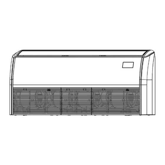
- Page 86 Installation layout Indoor unit Upper and lower louver Display panel Liquid pipe *Power supply cable and earth wires Air filter Air inlet grille *Connection wires Wired controller (optional) Remote controller (optional) * To be purchased separately on site. All the optional accessories should be from local dealer. For optional accessories such as wired controllers, please refer to the manuals of these accessories.
- Page 87 Liquid pipe(H) (Unit: mm) Capacity (kW) 1069 6.35 12.7 5.6< 1284 1199 9.52 15.9 9.0< 1649 1565 9.52 15.9...
- Page 88 The refrigerant pipe and drain pipe can be routed from two directions:bottom right and rear right. Refrigerant pipe routing direction Liquid pipe Right rear outlet Right bottom outlet Drainage pipe routing direction Drain pipe Right rear outlet Right bottom outlet...
- Page 89 When connecting the pipes,only cut the circular holes to avoid foreign objects from entering the machine. Right rear Right bottom Accessories List of accessories Installation And Flare Nut X 2 Drain Pipe X 1 Cable Tie X 8 Thermal Insulation Operation Manual X 1 Pipe X 2 (Make sure to hand it...
- Page 90 Locally Purchased Accessories Connecting piping (unit: mm) Piping Liquid side Capacity For connection of the IDU refrigerant system, it is recommended to use a soft copper tube (T2M), with the length Remarks selected according to the actual situation. Thermal insulation pipe Drain pipe The thickness of the insulation pipe This is used as the indoor unit's...
- Page 91 Check Before Installation Unpacking Check After unpacking, check whether the packing materials are in good condition, whether the accessories that come with the product are The red complete, whether the air conditioner is intact, whether the surfaces of dot bulges Sealing the heat exchanger and other parts are not worn, and whether there are oil stains on the stop valves of the unit.
- Page 92 Pipe Layout ① The deformed pipe area must not exceed 15% . ② A protective sleeve should be installed at the wall or floor hole. ③ The weld joint must not be inside the insulation. ④ The drill hole on the external wall must be sealed. Sleeve Wrapped Outdoors...
- Page 93 The bending angle should not exceed 90°; otherwise, wrinkles will be formed in the pipe, which can easily break. The bending radius should not be smaller than 3.5D (pipe diameter) and should be as large as possible to prevent the pipe from becoming flattened or crushed. When mechanically bending the pipe, the pipe bender inserted into the connecting pipe must be cleaned.
- Page 94 Handle Yoke Cone Connecting pipe Clamp handle Red arrow mark 3. Nut fastening Connect the indoor unit first, then connect the outdoor unit.Before tightening the flare nut, apply refrigeration oil on the inner and outer surface of the pipe flare (must use refrigeration oil compatible with the refrigerant for this model), and turn it 3 or 4 turns by hand to tighten it.When connecting or removing a pipe, use two wrenches at the same time.
- Page 95 When flared joints are reused indoors,the flare part should be re-fabricated. Pipe size (mm) Tightening torque [ N.m (kgf.cm)] 14.2–17.2 (144–176) 32.7–39.9 (333–407) 49.5–60.3 (504–616) 61.8–75.4 (630–770) 97.2–118.6 (990–1210) Excessive torque will damage the flared mouth and nut, and too small torque cannot tighten the nut, which will cause refrigerant leakage.
- Page 96 Leak Detection The leak test must satisfy the specifications of EN378-2. 1. To check for leaks: Vacuum leak test ① Evacuate the system from the liquid and gas piping to –100.7 kPa (–1.007 bar)(5 Torr absolute) for more than 2 hours. ②...
- Page 97 2. Reasons why refrigerant piping shall be insulated (1) The gas pipes and liquid pipes can become extremely hot or cool while in operation. Therefore, they should be insulated. Otherwise, the cooling and heating effects will be seriously impacted, and the compressor may become burnt.
- Page 98 b. Pipe connectors shall be properly insulated. No gaps shall be left here Unit No gaps shall be left at the place where insulation materials connect. If the connecting sections of insulation materials are pulled too much, or wrapped too tightly, these sections are likely to shrink and leave gaps, causing condensation and dripping.
- Page 99 When installing the insulation pipe on site, please cut it according to the actual needs. (Either method (a) or (b) is OK. Method (c) is incorrect. There must be no gap between the insulation pipe and connecting pipe.) Not connected Clearance Before installation of the drain pipe, determine its direction and elevation to avoid intersection with other pipelines to ensure that the slope is straight.
- Page 100 Water outlet pipe of indoor unit Drain pipe from the accessory package Connection method of the drainage pipe (Unit: mm) Method to discharge water with the natural drainage outlet: Air discharge The pipe faces downward to avoid intake of foreign matters. Vertical condensate pipe Requirements for slope of the drainage pipe: ①...
- Page 101 Installation requirement for drainage pipe The drainage pipe must be inclined downward (1/100 or above) to avoid condensate water flow. Drain pipe Downslope Downward PVC pipe (inner diameter 15mm) or rigid PVC pipe (VP-16)* Use PVC adhesives The end of the Upward Water accumulates drain pipe is...
- Page 102 Extend the drain pipe. To extend the length of a drain pipe, you need to purchase an extension drain pipe locally. Make sure the extension portion of the drain pipe indoors undergoes heat insulation treatment. Extended portion of the drainage pipe Drain pipe of indoor unit Insulation casing (purchased locally) Water outlet pipe of...
- Page 103 The number and type of cables may vary from model to model. Both ends of the cable are different, so make sure the cable end is correct before binding the pipes. The binding shall be seamless and neat in appearance. Install sealant and wall hole sleeve cover.
- Page 104 The power supply must be cut off before any electrical work is carried out. Do not conduct electrical work when the power is on; otherwise, it may cause serious personal injury. The air conditioning unit must be earthed reliably and must meet the requirements of the local country/region.
- Page 105 Electric specifications of the indoor unit Indoor Fan Motor(W) Capacity Rated power Frequency Voltage (kW) output (Hz) 0.20 0.16 0.22 0.28 0.43 0.34 0.45 0.36 0.60 0.48 220~240 0.75 0.60 10.0 0.63 0.50 0.75 0.60 11.2 1.00 0.80 12.5 1.25 1.00 14.0 NOTES:...
- Page 106 CN22 CN10 CN18 CN55 Terminals of remote Switch module M1 M2 X1 X2 D1(X) D2(Y) switch signal Power supply cable and Terminals of Communication terminals Terminals of earth line terminals strong current alarm signal sterilization output module Short-circuit terminal Display box T2 T2B (standard)/water Water pump...
- Page 107 Power supply cable must be routed separately from the other cable such as commucation wiring and display box commucation wiring. The strong and weak current wires must be separated. Power supply cable connection Connection between the power supply cable and power supply terminal Main control board The power supply terminal of the indoor unit is fixed on the main control board, the power supply cable is connected to the power...
- Page 108 The connected power supply cable should be secured with a wire clamp to prevent loosening, as shown in the right figure. Power supply cable system connection Power supply cable system connection depends on the methods of communication between the indoor unit and outdoor unit.
- Page 109 When the indoor units are provided with a unified power supply, if the indoor units in the same refrigerant system are indoor units, then indoor units and outdoor unit can communicate either via P/Q. If some of the indoor units in the same refrigerant system are non- series, then indoor units and outdoor unit can only communicate via P/Q/E communication.
- Page 110 Table of selection of communication wiring diameter One controller One-to-more to one indoor unit (centralized Function Indoor unit and outdoor unit communication (Two controllers controller) to one indoor unit) Communication Communication P/Q/E P/Q communication communication X1X2 D1D2 Item (Indoor units are (Indoor units are communication communication...
- Page 111 Indoor unit and outdoor unit communication P/Q communication Single unit: Use a shielded cable for the P/Q communication and properly earth the shield layer. P and Q ports are located at terminal block "CN6" of the main control board. There is no distinction between negative and positive electrodes.
- Page 112 P/Q/E communication If some of the indoor units in the same refrigerant system are non- series, it is required to connect "P", "Q", and "E" for P/Q/E communication. Single unit: Use a shielded cable for the P/Q/E communication and properly earth the shield layer. P, Q, and E ports are located at terminal block "CN6"...
- Page 113 When P/Q or P/Q/E communication is used, the indoor units need to be powered uniformly. Use only shielded cables for P/Q or P/Q/E communication. Otherwise, the indoor unit and outdoor unit communication may be affected. A matching resistor needs to be added to the last indoor unit on the PQ (in the accessory bag of the outdoor unit).
- Page 114 D1D2 communication wiring connection (limited to outdoor unit and system configuration) Achieving one-to-multiple and two-to-multiple functions of the indoor unit wired controller through D1D2 communication (a maximum of 16 sets) D1D2 communication is 485 communication. The one-to-more and two-to-more functions of the indoor unit wired controller can be achieved through D1D2 communication, as shown in the figure below: Indoor unit 2# Indoor unit 16#...
- Page 115 External boards connection (limited to outdoor unit and system configuration) The external boards are connection module outside the main control board, including Switch module, 1# Expansion board and 2# Expansion board. Connection of Display Box The display box is connected to the main control board through a 4-core cable, and is connected to the "CN30"...
- Page 116 Alarm signal and Sterilization module Refer to the following figure for the wiring of alarm signal and Sterilization module. Main CN22 control Output voltage: 220 VAC; board The output voltage is 220-240V~. Maximum output power: 220 W Strong current sterilization module Alarm signal output Output voltage: 220 VAC;...
- Page 117 The error code is displayed on the display box and the wired controller display. Definition Error code Digital display Emergency stop R32 refrigerant leaks, requiring shutdown immediately Outdoor unit fault Interlocking control Heat Recovery Ventilation Unit fault( in-series application) The Humidity Unit fault Interlocking control Heat Recovery Ventilation Unit fault(non-serial application) The AHU Kit slave unit fault Self-check fault...
- Page 118 Error Error code Digital display Abnormal communication between the indoor unit and outdoor unit Abnormal communication between the indoor unit main control board and fan drive board Abnormal communication between the indoor unit and wired controller Abnormal communication between the indoor unit and Wi-Fi Kit Abnormal communication between the indoor unit main control board and display board Abnormal communication between the AHU Kit slave unit and master unit Number of AHU Kits is not the same as the set number...
- Page 119 Error Error code Digital display The built-in room temperature sensor of the wired controller short-circuits or cuts off The wireless temperature sensor short-circuits or cuts off The external room temperature sensor short-circuits or cuts off Tcp (pre-cooled fresh air temperature sensor) short-circuits or cuts off Tph (pre-heated fresh air temperature sensor) short-circuits or cuts off TA (outlet air temperature sensor) short-circuits or cuts off Outlet air humidity sensor fault...
- Page 120 Error Error code Digital display Low bus voltage fault High bus voltage fault Phase current sample bias error Motor and indoor unit are unmatched IPM and indoor unit are unmatched Motor startup failure Motor blocking protection Speed control mode setting error Phase lack protection of motor Definition Code...
- Page 121 Use the bi-directional communication wired controller (for example, WDC3-86S) to activate the spot check function in the following steps: Check No. Spot check enter the query page. The wired controller parameters indoor unit address n00-n74 (indicating the address of a specific indoor unit), and press the "...
- Page 122 After the installation of the unit, check the items listed below first. Do not power on the system. Pass/Fail Check list Read the complete installation and operation manual. Installation Check that the units are properly installed, to avoid abnormal noises and vibrations when starting up the units. Compressor and others shipping brackets removed.
- Page 123 Pass/Fail Check list Oil leak Check if there is oil leaking from the compressor and piping. If there is an oil leak, try to repair the leak. If the repair is not successful, please call the local agent. Refrigerant leak Check for refrigerant leaks inside the unit.
-
Page 124: Maintenance And Service
Maintenance and Service Wipe the air outlet and panel with a dry cloth. If a stain is hard to remove, clean it with clean water or neutral detergent. Do not use gasoline, benzene, volatile agents, decontamination powder or liquid insecticides. Otherwise, the air outlet or panel may become discolored or deformed. - Page 125 Air filters can be used to remove dust or other particles from the air, and if clogged, the effectiveness of the air conditioner will be greatly reduced. Therefore, be sure to clean the air filter frequently when using it for an extended period.If it is installed in a place with a lot of dust, it is recommended that you clean the filter once a month.
- Page 126 To avoid deformation of the filter, do not use fire or a burning appliance to dry the filter. If the filter is dirty, use a soft brush and neutral detergent to clean it, then shake off the water and dry it in a cool place.
- Page 127 Remove the air inlet grille. Loosen the two screws, remove the electric control box and repair it. electric control box 、 Remove the air inlet grille.
- Page 128 Remove upper propeller casing. Horizontally remove the motor and wind wheel;loosen the fixing screws between the motor and wind wheel,and perform maintenance on the motor and wind wheel. Remove lower propeller casing and perform maintenance.
- Page 129 Points of attention for volute assembly: slot and tongue, limit slot and side wall alignment and then buckle; Check again whether the limit slot, positioning column and buckle are installed in place, and the limit tongue should cover the outside of the volute. Remove the cover plate.
- Page 130 Remove the pipe clamping plate. Remove the evaporator and perform maintenance.
-
Page 133: À Propos De La Documentation
À propos de la documentation... -
Page 136: Avertissement De Sécurité
Avertissement de sécurité >... - Page 137 REMARQUE: Pour les unités utilisant du réfrigérant R32, seul un fusible céramique anti-explosion doit être employé.
- Page 140 • un équipement de manutention mécanique est disponible, si nécessaire, pour transporter les cylindres de réfrigérant ; • tous les équipements de protection individuelle sont disponibles et utilisés correctement ; • le processus de récupération est supervisé à tout moment par une personne compétente ; •...
- Page 141 Fonctionnement 1. Toucher des pièces mobiles ou sous tension, telles que des ventilateurs, des moteurs ou des volets, par un non professionnel. Les pièces en marche peuvent vous blesser ou les ensembles de transmission peuvent être endommagés. 2. S'approcher trop près du climatiseur peut réduire le niveau de confort.
- Page 142 Ne jetez pas les appareils électriques avec les déchets ménagers ordinaires ; portez-les dans les installations de collecte qui existent près de chez vous. Contactez votre gouvernement local pour obtenir des renseignements sur les systèmes de collecte disponibles. Si les appareils électriques sont jetés dans des décharges ou des dépôts, des substances dangereuses peuvent s'infiltrer dans les eaux souterraines et entrer dans la chaîne alimentaire, engageant votre santé...
- Page 147 Installation...
- Page 150 > >...
-
Page 189: Maintenance Et Entretien
Maintenance et entretien... - Page 201 2.5m...
- Page 204 • • • •...
- Page 208 Temperatura 16~32 °C interior interior Temperatura 15~30 °C interior...
- Page 209 • • • • • • • •...
- Page 210 • • Todas...
- Page 212 Lea atentamente este manual antes de instalar la unidad interior. Produtos designados...
- Page 215 Es fácil suministrar flujo de aire a todos los rincones de la sala. Evite instalar la unidad en espacios reducidos o donde los requisitos acústicos sean más estrictos. > >...
- Page 216 Esquema de instalación...
- Page 217 de g s (F) de líquido (H) 1069 1284 1199 1649 1565...
- Page 218 de líquido de g s...
- Page 220 Pot ncia...
- Page 221 Fuga...
- Page 222 ≥ Exterior Interior...
- Page 223 soldadura refrigerante Válvula manual Cortatubos 90°±4 Máx. Mín. R0.4–0.8...
- Page 224 Barra Barra...
- Page 225 20~40 Unidad Unidad interior exterior Válvula Manómetro de Bomba...
- Page 228 Unidad...
- Page 230 • Descarga de a 1000~1500 mm...
- Page 235 (kW) (Hz) 0.20 0.16 0.28 0.22 0.43 0.34 0.45 0.36 0.60 0.48 220~240 0.75 0.60 0.63 0.50 10.0 0.75 0.60 11.2 1.00 0.80 12.5 1.25 1.00 14.0...
- Page 236 CN22 CN10 CN18 CN55 M1 M2 X1 X2 D1(X) D2(Y) T2 T2B...
- Page 238 × × × × CN22 ··· × × × × CN22 ···...
- Page 240 ② Elemento X1X2 D1D2 1200 m 200 m 1200 m 1200 m...
- Page 241 × × × × CN22 ··· L1+La+Ln ≤ 1200 m...
- Page 242 P Q E × × × × CN22 ··· L1+La+Ln ≤ 1200 m...
- Page 243 X1X2 X1X2 L1 ≤ 200 m, L2+L3 ≤ 200m.
- Page 244 D1 D2 D1 D2 D1 D2 X1 X2 X1 X2 X1 X2 L1+L2 ≤ 200 m, L3+Ln ≤ 1200 m D1 D2 D1 D2 D1 D2 ··· L1+L3+Ln ≤ 1200 m...
- Page 245 CN30 Placa de control visualiza principal ② CN18 CN18 CN10 CN10 +12V GND E1 E2 +12V GND E1 E2 CN18 CN10 CN10 +12V GND E1 E2 +12V GND E1 E2...
- Page 246 Placa de CN22 principal CN55 Interruptor remoto...
- Page 251 ② ③ ④...
- Page 253 • • • • • • • •...
- Page 256 ① ② ③...
- Page 258 Motor...
Need help?
Do you have a question about the JR8 SLT Series and is the answer not in the manual?
Questions and answers