Table of Contents
Advertisement
Available languages
Available languages
Quick Links
Advertisement
Table of Contents

Related Manuals for Johnson VARI CST Series


Summary of Contents for Johnson VARI CST Series
- Page 2 Prefacio Estimados usuarios: Para garantizar el funcionamiento correcto y seguro del producto, siga estrictamente los requisitos que se indican en este manual. Todas las figuras y contenidos de este manual son sólo a modo de referencia. Debido a la continua mejora del producto, las especificaciones están sujetas a cambios sin previo aviso.
-
Page 4: Señales De Advertencia
Advertencia Por favor, lea detenidamente y asegúrese de entender completamente las precauciones de seguridad (incluyendo las señales y los símbolos) de seguridad de este manual, y siga las instrucciones pertinentes durante el uso para evitar daños a la salud o a la propiedad. Explicación de los símbolos que se muestran en la unidad Este símbolo indica que este aparato utiliza un gas refrigerante inflamable. -
Page 5: Precauciones De Seguridad
Contenido de advertencia Asegúrese de una Sólo para profesionales correcta conexión a tierra Señal de prohibición Prohibido el uso de Prohibido el uso de Prohibido el uso Prohibido el uso de materiales inflamables corrientes fuertes de fuego materiales ácidos o alcalinos abierto Precauciones de seguridad [Peligro]... - Page 6 Requisitos de seguridad eléctrica [ Advertencia ] El aire acondicionado debe instalarse de acuerdo con las especificaciones locales en materia de cableado. Los trabajos de cableado deben ser realizados por electricistas cualificados. Todos los trabajos de cableado deben cumplir las especificaciones de seguridad eléctrica. El equipo de aire acondicionado debe estar bien conectado a tierra.
- Page 7 Asegúrese de que el equipo de detección de fugas utilizado sea apto para su uso con refrigerantes inflamables; es decir, no genere chispas, esté adecuadamente sellado o sea intrínsecamente seguro. Si se va a realizar algún trabajo en caliente en el equipo de refrigeración o en cualquiera de sus piezas, deberá disponer de un equipo de extinción de incendios adecuado.
- Page 8 Verifique que el cableado no esté sometido a desgaste, corrosión, presión excesiva, vibración, bordes afilados o cualquier otro efecto ambiental adverso. La verificación deberá asimismo tener en cuenta los efectos del envejecimiento o de la vibración continua de fuentes como compresores o ventiladores. Al entrar en el circuito del refrigerante para hacer reparaciones –...
- Page 9 Cuando transfiera refrigerante a los cilindros, asegúrese de que sólo se empleen cilindros de recuperación de refrigerante adecuados. Asegúrese de que estén disponibles el número correcto de cilindros para mantener la carga total del sistema. Todos los cilindros que se van a utilizar deberán estar designados para el refrigerante recuperado y etiquetados para dicho refrigerante (es decir, cilindros especiales para la recuperación del refrigerante).
-
Page 10: Precauciones De Funcionamiento
Funcionamiento Precauciones de funcionamiento [ Advertencia ] Si la unidad no se va a utilizar durante mucho tiempo, desconecte el interruptor principal. De lo contrario, podría producirse un accidente. La altura de instalación del aire acondicionado deberá ser de al menos 2,5 m sobre el suelo para evitar los siguientes riesgos: Tocar piezas móviles o con corriente, como ventiladores, motores o rejillas, por parte de una persona no profesional. -
Page 11: Funcionamiento Óptimo
Eliminación: No deseche este producto como residuo municipal no clasificado. Es preciso que se recojan estos residuos por separado para recibir un tratamiento especial. No deseche los aparatos eléctricos como residuos municipales no clasificados , utilice instalaciones de recogida específicas. Póngase en contacto con sus autoridades locales para obtener información sobre los sistemas de recogida disponibles. - Page 12 Rango de funcionamiento Para mantener un buen rendimiento, haga funcionar el aire acondicionado bajo las siguientes condiciones de temperatura: Temperatura interior 16~32°C Refrigeración (Cuando la humedad supera el 80%, el funcionamiento prolongado de la Humedad interior IDU puede provocar condensación en su superficie o generar aire frío en forma de niebla por la salida del aire).
- Page 13 Fenómenos normales que no son fallos del aire acondicionado Los siguientes fenómenos son normales durante el funcionamiento del aire acondicionado. Pueden solucionarse de acuerdo con las instrucciones que se indican a continuación, o bien no es necesario solucionarlos. La IDU emite niebla blanca En un entorno en el que la humedad relativa interior es demasiado alta, cuando la IDU funciona en modo de refrigeración, puede aparecer neblina blanca debido a la humedad y a la diferencia de temperatura entre la entrada y la salida de aire.
-
Page 14: Panel De Visualización
Panel de visualización Funciones de pantalla: En el modo de espera, la interfaz principal muestra “---”. Al ponerse en marcha en modo de Refrigeración o de Calefacción, la interfaz principal muestra la temperatura establecida. En el modo de Ventilador, la interfaz principal muestra la temperatura interior. En el modo Seco, la interfaz principal muestra la temperatura establecida y, cuando se ajusta la humedad, el valor de humedad ajustado se muestra en el controlador con cable. -
Page 15: Precauciones De Instalación
Instalación Lea atentamente este manual antes de instalar la IDU. Precauciones de instalación Requisitos de cualificación y normativas de seguridad [ Advertencia ] Realice la instalación de acuerdo con las normas locales. Solicite a su distribuidor local o a profesionales que instalen el producto. Esta unidad debe ser instalada por técnicos profesionales con los conocimientos especializados pertinentes. - Page 16 Antes y después de la instalación, la exposición de la unidad al agua o a la humedad provocará cortocircuitos en las piezas eléctricas. No almacene la unidad en un sótano con humedad ni la exponga a la lluvia o al agua. Asegúrese de que la base de instalación y la elevación son robustas y fiables;...
- Page 17 Precauciones para transportar y levantar el equipo de aire acondicionado Antes de transportar el equipo de aire acondicionado, determine la ruta que se utilizará para su traslado al lugar de instalación. No desprecinte el equipo de aire acondicionado hasta que sea trasladado al lugar de instalación. Al desembalar y trasladar el aire acondicionado, debe sujetar el asiento de suspensión y no aplicar fuerza sobre otras piezas, especialmente la tubería de refrigerante, la tubería de desagüe y los accesorios de plástico, para evitar dañar el aire acondicionado y causar lesiones personales.
- Page 18 Cuanto más cerca estén la tubería de desagüe y la tubería de cobre de la ODU, menor será el recorrido de la tubería. Evite que el aire acondicionado incida directamente sobre el cuerpo humano. Cuanto más cerca esté el cableado del armario eléctrico, menor será el coste del cableado. Mantenga el aire de retorno del aire acondicionado lejos de la exposición directa al sol en la sala.
- Page 19 Techo Salida de aire Salida de aire Panel Entrada de aire 590 × 590 (dimensiones de la abertura del techo) Suelo...
- Page 20 Lugares de instalación recomendados Lugares concurridos como salas de estar y oficinas Bloqueo Bloqueo de salida de aire Esquema de una salida de aire bloqueada Utilice un cuchillo para cortar el bloqueo del material de embalaje. Comedor Habitualmente, el comedor se encuentra situado junto a la cocina que suele estar llena de humos aceitosos, por lo que el aire acondicionado central puede instalarse en el techo entre el comedor y la cocina.
-
Page 21: Descripción De Piezas
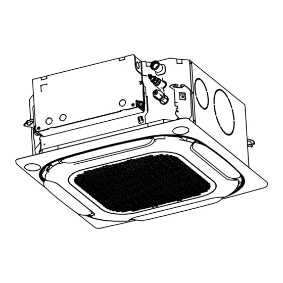
Piezas Descripción de piezas Panel (opcional) Salida de aire Entrada/salida de aire expandido Entrada de aire fresco Tubería de líquido Tubería de gas Tubería de desagüe *Cable de conexión Controlador con cable (opcional) Controlador remoto (opcional) Caja de control eléctrico Orificio de acceso *Cable de alimentación y *Línea de comunicación... -
Page 22: Dimensiones Del Producto
Dimensiones del producto (Unidad: mm) 6-M4 6-M4 6-M4 620 (con panel) Tubería de desagüe A: Conectar a las tuberías de B: Conectar a las tuberías de Modelo (kW) refrigerante (lado del líquido) refrigerante (lado del gas) -
Page 23: Lista De Accesorios
Materiales de instalación Accesorios Lista de accesorios Manual de instalación y del Tuerca de latón × 2 Brida sujetacables × 4 Tubo de aislamiento térmico × 2 propietario × 1 Para apretar firmemente la Para usar en la instalación de la Se utiliza para el aislamiento y Instrucciones de instalación de manguera de drenaje a la salida... - Page 24 Accesorios adquiridos localmente Lista de accesorios Tubo de cobre Tubo de descarga de Tubo de aislamiento Tornillo de expansión Tornillo de elevación agua de PVC térmico (M10) × 4 (M10) × 4 Se utiliza para conectar Se utiliza para drenar el Se utiliza para evitar Se utiliza para instalar Se utiliza para instalar...
-
Page 25: Preparativos Antes De La Instalación
Preparativos antes de la instalación Comprobación de desembalaje El punto rojo Antes de la instalación, compruebe que los materiales de embalaje están en sobresale buen estado, que los accesorios que acompañan al producto están Sellado completos, que el equipo de aire acondicionado está intacto y que las superficies del intercambiador de calor y otras piezas no están desgastadas. - Page 26 Corte un orificio con un tamaño de 590 mm × 590 mm según (Unidad: mm) el contorno del cartón de montaje. Corte con la forma del cartón de montaje 378± 1 530±1 (distancia de suspensión) 575±1 (tamaño de la IDU) 590 (dimensiones de la abertura del techo) [ Precaución ] Alinee el centro de la caja del techo con el del cuerpo principal del aire acondicionado.
- Page 27 (Unidad: mm) Para conocer las dimensiones de las aberturas del techo, consulte la siguiente figura. Conectar a la Instalación de tubería de desagüe los suspensores Conectar a las tuberías de refrigerante (lado del líquido) Tuerca hexagonal Conectar a las (Ajuste de nivel) tuberías de refrigerante (lado del gas)
- Page 28 Consulte la siguiente tabla sobre la instalación usando los pernos de elevación. Con bastidor de acero Sitios con losas de hormigón Utilice pernos embebidos y pernos a tracción Ajuste directamente y utilice una escuadra de hierro como soporte. Pernos de elevación Pernos de Escuadra de elevación...
- Page 29 Confirme la posición del gancho de instalación según los orificios del gancho de instalación situados en las cuatro esquinas del cartón de montaje. Durante la instalación, oriente la superficie cóncava del gancho de montaje hacia el gancho de expansión, determine la longitud adecuada del gancho de montaje según la altura del techo y corte la parte sobrante. Se deben utilizar pernos M10 o W3/8 para instalar el tornillo del gancho.
- Page 30 Brida de aire fresco Tornillos de conexión de la brida (6 uds.) [ Advertencia ] Cuando conecte la unidad de aire fresco, aísle la tubería de aire fresco con materiales aislantes de espuma de al menos 10 mm de grosor. La diferencia de temperatura entre el aire fresco suministrado por la unidad de aire fresco a la IDU y la temperatura interior no deberá...
- Page 31 Cuerpo principal del aire acondicionado Tornillo M6 × 20 Cartón de montaje (Panel) Realice la instalación como se ha descrito anteriormente (punto 3 de la instalación del Techo existente). Retire el cartón de montaje. [ Nota ] Asegúrese de que la unidad IDU esté nivelada: utilice un nivel de burbuja o una manguera de goma transparente llena de agua para corregir el nivel de la IDU;...
- Page 32 Instalación del panel Instale el panel en la IDU con pernos (M5 × 20) y arandelas. Lado de drenaje Pernos y arandelas Asegúrese de que los dos ganchos están bien sujetos. Gancho de panel (dos) Apriete los tornillos situados debajo de los ganchos del panel hasta que el grosor de las esponjas de sellado 1 y 2 entre la IDU y la salida del panel se reduzca a unos 4–6 mm.
- Page 33 [ Precaución ] Un apriete incorrecto de los tornillos puede provocar el fallo que se muestra en la figura siguiente. Después de apretar los tornillos, si todavía queda espacio entre el techo y el panel, se debe volver a ajustar la altura de la IDU. Si el nivel de elevación de la IDU y las tuberías de desagüe no se ven afectadas, puede retirar el panel y volver a ajustar la altura de la IDU.
- Page 34 Instalación de las tuberías de conexión de refrigerante Requisitos de longitud y diferencia de nivel para las conexiones de tuberías de la IDU y la ODU Las diferentes ODU tienen diferentes requisitos de longitud y de diferencias de nivel para las tuberías.
- Page 35 Pasos para la conexión de la tubería Mida la longitud necesaria de la tubería de conexión. Prepare la tubería de conexión siguiendo el siguiente método (véase "Conexión de la tubería" para más detalles). Conecte primero la IDU y, a continuación, la ODU. Antes de apretar la tuerca cónica, aplique aceite de refrigeración en la superficie interior y exterior del abocardado de la tubería (para este modelo, debe utilizar aceite de refrigeración compatible con el refrigerante) y gírela 3 ó...
- Page 36 Desplazamiento del nitrógeno Al soldar las tuberías, llénelas con nitrógeno. Caliente primero de forma uniforme los tubos interiores y luego los exteriores, y llene las juntas con material de soldadura. [ Advertencia ] Cuando sea necesario llenar la tubería con nitrógeno durante la soldadura, la presión debe mantenerse a 0,02 MPa utilizando una válvula de alivio de presión.
- Page 37 La tuerca protectora es una pieza de un solo uso, no se puede reutilizar. En caso de que se retire, debe sustituirse por una nueva. (Sólo para la norma IEC 60335-2-40: 2018) Manilla Barra Barra Horquilla Cono Tubo de cobre Manija de la abrazadera Marca de flecha roja Tuerca protectora...
-
Page 38: Detección De Fugas
Bombeo de vacío Válvula de retención Manómetro de alta presión Válvula de la bomba Manómetro de baja presión Bomba de vacío Detección de fugas Llene el sistema con nitrógeno y aumente su presión para detectar fugas. Se recomiendan los siguientes métodos: Con espuma Aplique agua jabonosa o espuma de manera uniforme (pulverizar) en las zonas donde pueda haber fugas y observe si aparecen burbujas de aire. -
Page 39: Instalación De La Tubería De Desagüe
Instalación de la tubería de desagüe [ Precaución ] Antes de instalar la tubería de condensado, determine su dirección y elevación para evitar la intersección con otras tuberías y asegurar que la pendiente sea lisa y recta. El punto más alto de la tubería de desagüe debe estar equipado con un puerto de descarga para garantizar una descarga suave del agua de condensación, y el puerto de descarga debe estar orientado hacia abajo para evitar que entre suciedad en la tubería. - Page 40 Brida sujetacables Tubería de desagüe Tubo de aislamiento térmico Para evitar que el agua vuelva a entrar en el aire acondicionado cuando éste deje de funcionar, la tubería de desagüe debe estar inclinada hacia el lado exterior (lado de desagüe), con una pendiente descendente de 1/100 o más.
- Page 41 El extremo de la tubería de desagüe debe estar a más de 50 mm del suelo o de la base de la ranura de descarga de agua. Además, no lo sumerja en agua. Para descargar el agua condensada directamente en una zanja, el tubo de descarga de agua debe doblarse hacia arriba para formar a fin de evitar que los olores entren en la sala a través del tubo de descarga de agua.
- Page 42 Prueba de descarga de agua Antes de la prueba, asegúrese de que la tubería de descarga de agua esté lisa, y verifique que cada conexión esté bien sellada. Realice la prueba de descarga de agua en una sala nueva antes de enlucir el techo. La tubería de desagüe puede ser de PVC (diámetro externo: 25 mm).
-
Page 43: Conexiones Eléctricas
Conexiones eléctricas [Peligro] [ Advertencia ] [ Precaución ]... -
Page 44: Características Eléctricas
Características eléctricas Especificaciones eléctricas de la IDU Potencia de la Entrada de Frecuencia Tensión unidad (kW) potencia IFM (Hz) 0,46 0,37 0,46 0,37 0,54 0,43 220~240 0,54 0,43 0,61 0,49 0,65 0,52 0,81 0,65 Notas: MCA: Amperios mín. del circuito (A) que se utiliza para seleccionar el tamaño mínimo del circuito con el fin de garantizar un funcionamiento seguro durante un largo período de tiempo. - Page 45 [ Precaución ] Todas las conexiones de los puntos débiles cumplen con el sistema SELV, como X1, X2, P, Q, E, M1, M2, CN18, CN55, etc. Cableado Abrir la tapa de la caja de control eléctrico de la IDU. Retire los dos tornillos en las posiciones que se muestran en la figura; Tire del extremo inferior de la tapa de la caja de control eléctrico horizontalmente hacia fuera;...
-
Page 46: Conexión Del Cable De Alimentación
Conexión del cable de alimentación Conexión entre el cable de alimentación y el terminal Placa de control principal de la fuente de alimentación El terminal de alimentación de la IDU se fija a la placa de control principal y el cable de alimentación se conecta al terminal de alimentación etiquetado como... - Page 47 Conexión del sistema del cable de alimentación La conexión del sistema de cables de alimentación depende de las formas de comunicación entre la IDU y la ODU. Las IDU están provistas de una fuente de alimentación uniforme*, que se cablea de la siguiente manera: .
- Page 49 Conexión de la línea de comunicación Selección del método de comunicación para las IDU Método de comunicación Tipo de IDU Observaciones opcional entre las IDU y la ODU Las IDU deben recibir alimentación uniforme. Todas las IDU del Los cables de comunicación deben estar sistema son de la conectados en serie.
- Page 50 Tabla de selección de diámetro de la línea de comunicación controlador para una IDU uno a más Función Comunicación de IDU y ODU (Dos controladores para una IDU) Comunicación P/Q/E Comunicación P/Q Comunicación Comunicación (Las IDU se (Las IDU se D1D2 X1X2 Elemento...
- Page 51 Comunicación de IDU y ODU Comunicación P/Q Unidad individual: utilice un cable blindado para la comunicación P/Q y conecte a tierra correctamente la capa de blindaje. Los puertos P y Q se encuentran en el bloque de terminales “CN6” de la placa de control principal.
- Page 52 Comunicación P/Q/E Si algunas de las IDU del mismo sistema de refrigeración no son de la serie , es necesario conectar "P", "Q" y "E" para la comunicación P/Q/E. Unidad individual: Utilice un cable blindado para la comunicación P/Q/E y conecte a tierra correctamente la capa de blindaje.
- Page 53 Conexión del cable de comunicación X1/X2 La línea de comunicación X1X2 se conecta principalmente al controlador con cable para obtener un controlador por cada IDU y dos controladores por cada IDU. La longitud total de la línea de comunicación X1X2 puede alcanzar los 200 metros.
- Page 54 Conexión de la línea de comunicación D1D2 (se limita a a la ODU y a la configuración del sistema) Obtener las funciones de uno a varios y de dos a varios del controlador con cable de la IDU a través de la comunicación D1D2 (un máximo de 16) La comunicación D1D2 es una comunicación 485.
- Page 55 Conexión de la placa externa (se limita a la ODU y a la configuración del sistema) La placa externa es un módulo de conexión fuera de la placa de control principal que incluye un panel de visualización, una placa adaptadora de módulos de funciones y las tarjetas de expansión de funciones 1 y 2 opcionales.
- Page 56 Volver a cerrar la tapa de la caja de control eléctrico Extienda los cables de conexión y póngalos en posición horizontal; vuelva a cerrar la tapa de la caja de control eléctrico. [ Precaución ] No cubra la caja de control eléctrico durante el encendido. Cuando cubra la caja de control eléctrico, coloque los cables con cuidado y no sujete los cables de conexión en la tapa de la caja de control eléctrico.
- Page 57 Control de aplicaciones Códigos de error y definiciones Error Código de error Pantalla digital Parada de emergencia Fugas de refrigerante R32, que requieren una parada inmediata Fallo de la ODU El fallo de la FAPU vinculada se transmite a la IDU maestra (ajuste en serie) El fallo de la IDU de humidificación vinculada se transmite a la IDU maestra El fallo de la FAPU vinculada se transmite a la IDU maestra (ajuste no en serie) El fallo de la unidad esclava del kit AHU se envía a la unidad maestra...
- Page 58 Error Código de error Pantalla digital Comunicación anormal entre la IDU y la ODU Comunicación anormal entre la placa de control principal de la IDU y la placa de accionamiento del ventilador Comunicación anormal entre la IDU y el controlador con cable Comunicación anormal entre la IDU y el kit Wi-Fi Comunicación anormal entre la placa de control principal de la IDU y la placa de visualización Comunicación anormal entre la unidad maestra y la unidad esclava del kit AHU...
- Page 59 Error Código de error Pantalla digital El sensor de temperatura de la sala integrado en el controlador con cable se cortocircuita o se desconecta El sensor de temperatura inalámbrico se cortocircuita o se desconecta El sensor externo de temperatura de la sala se cortocircuita o se desconecta Tcp (sensor de temperatura del aire fresco preenfriado) se cortocircuita o se desconecta Tph (sensor de temperatura del aire fresco precalentado) se cortocircuita o se desconecta TA (sensor de temperatura del aire de salida) se cortocircuita o se desconecta...
- Page 60 Error Código de error Pantalla digital Fallo de baja tensión del bus Fallo de alta tensión del bus Error de sesgo de muestra de corriente de fase El motor y la IDU no se corresponden IPM e IDU no coinciden Fallo de arranque del motor Protección de bloqueo del motor Error de ajuste del modo de control de velocidad...
- Page 61 Descripción de la comprobación puntual N.º de 2seg. para entrar en la página de consulta. La ODU muestra u00- comprobación u03, la IDU muestra n00-n63 (los dos últimos dígitos indican la dirección de la IDU), y el controlador con cable muestra CC. Parámetros de Pulse comprobación...
- Page 62 Ajuste ESP Modo de velocidad constante Para ajustar los parámetros de presión estática externa de la unidad y vencer la resistencia de salida del aire, se debe utilizar el controlador con cable de comunicación bidireccional. Los pasos son los siguientes: En la página principal, mantenga pulsados "...
-
Page 63: Prueba De Funcionamiento
Prueba de funcionamiento Antes de la prueba de funcionamiento, asegúrese de que: Las IDU y la ODU están instaladas correctamente. Las tuberías son correctas y se ha comprobado que el sistema de tuberías de refrigerante no presenta fugas. Se ha registrado la longitud de las tuberías y la cantidad de refrigerante cargado. El cableado es correcto y firme sin problemas de conexión virtual. - Page 64 Inspección después de la instalación Para asegurar un ambiente interior confortable, por favor repase la lista para comprobar si la instalación del Resultado de la comprobación Elementos de comprobación Criterios de comprobación (aprobado/no aprobado) El aire acondicionado no se cae ni vibra, y ¿Están las IDU y las ODU instaladas de forma segura? no hace ruido.
-
Page 65: Advertencia De Seguridad
Limpieza, Mantenimiento y Servicio Posventa Advertencia de seguridad [ Advertencia ] Por razones de seguridad, apague siempre el aire acondicionado y desconecte la corriente antes de limpiarlo. No desmonte ni repare el aire acondicionado usted mismo; de lo contrario, podría provocar un incendio u otros peligros. - Page 66 Diagrama de procedimiento Retire la rejilla de entrada de aire Presione la abrazadera de la rejilla con dos dedos al mismo tiempo y extraiga la rejilla de entrada de aire en dirección hacia abajo. Gire la abrazadera de la rejilla hacia el centro.
-
Page 67: Mantenimiento
Limpieza de las salidas de aire y los paneles exteriores Limpie la salida de aire y el panel con un paño seco. Si una mancha es difícil de eliminar, límpiela con agua limpia o detergente neutro. [ Precaución ] No use gasolina, benceno, agentes volátiles, polvo de descontaminación o insecticidas líquidos. De lo contrario, la salida de aire o el panel podrían decolorarse o deformarse. - Page 68 Mantenimiento de las piezas convencionales Mantenimiento de la placa de control eléctrico Extraiga la placa de control principal. Abrir la tapa de la caja de control eléctrico. Retire los dos tornillos en las posiciones indicadas en la figura y extraiga el extremo inferior de la tapa de la caja de control eléctrico en sentido horizontal.
- Page 69 Abra la tapa de la caja de control eléctrico y suelte la brida para cables. Tornillos (dos) Tapa de la caja de control eléctrico Tornillo (tres) Conjunto de la placa de sellado Vuelva a colocar el ventilador después de quitar las tuercas en el centro del ventilador y el clip del ventilador.
- Page 70 Mantenimiento del evaporador Desconecte los terminales correspondientes en la placa de control principal. Siga los pasos anteriores para retirar el panel y la bandeja de drenaje. Retire el conjunto de la placa de sellado. Después de quitar un tornillo de fijación, retire la placa de fijación del evaporador.
- Page 71 Mantenimiento de la bomba de agua Desconecte el terminal de la bomba de agua en la placa de control principal. Siga los pasos anteriores para retirar el panel y la bandeja de drenaje. Desconecte la tubería de desagüe. Retire los tornillos que fijan la bomba de agua y el soporte Una vez retirados los dos tornillos de fijación, la bomba puede extraerse...
- Page 73 Preface De a r us ers , Thank you for purchasing and using our product. Please read this manual carefully before you install, use, maintain or troubleshoot this product so that you can familiarize yourself with the product and use it correctly. For ODUs or other IDUs, please refer to the applicable installation &...
-
Page 75: About The Documentation
About The Documentation About This Document Note Make sure that the user has the printed documentation and ask him/her to keep it for future reference. Target audience Authorised installers + end users Note This appliance is intended to be used by expert or trained users in shops, in light industry, and on farms, or for commercial and household use by lay persons. -
Page 76: Safety Signs
Specific Installer Safety Instructions Please thoroughly read and ensure that you fully understand the safety precautions (including the signs and symbols) in this manual, and follow relevant instructions during use to prevent damage to health or property. Safety signs Indicates a hazard with a high level of risk which, if not avoided, will result in death or Danger serious injury. -
Page 77: Safety Warning
Safety Warning Warning contents Professional Only Ensure Proper Prohibition signs No Laying No Strong Currents No Open Flame; No Acid or Inflammable Thing Fire, Open Ignition Alkali Materials Source and Smoking Prohibited Safety Precautions Danger In the event of refrigerant leakage, smoking and open flames are prohibited. Disconnect the main power switch immediately, open windows to allow ventilation, keep away from the leakage point, and contact your local dealer or technical support to request a professional repair. - Page 78 Caution This appliance can be used by children aged from 8 years and above and persons with reduced physical, sensory or mental capabilities or lack of experience and knowledge if they have been given supervision or instruction concerning use of the appliance in a safe way and understand the hazards involved. Children shall not play with the appliance.
-
Page 79: About The Refrigerant
About The Refrigerant Warning The following applies to R32 refrigerant systems. Prior to beginning work on systems containing flammable refrigerants, safety checks are necessary to ensure that the risk of ignition is minimized. For repair to the refrigerating system, the following precautions shall be complied with prior to conducting work on the system. - Page 80 During repairs to sealed components, all electrical supplies shall be disconnected from the equipment being worked upon prior to any removal of sealed covers, etc. If it is absolutely necessary to have an electrical supply to equipment during servicing, then a permanently operating form of leak detection shall be located at the most critical point to warn of a potentially hazardous situation.
- Page 81 i) Do not exceed the maximum working pressure of the cylinder, even temporarily. j) When the cylinders have been filled correctly and the process completed, make sure that the cylinders and the equipment are removed from site promptly and all isolation valves on the equipment are closed off. k) Recovered refrigerant shall not be charged into another refrigeration system unless it has been cleaned and checked.
-
Page 82: Operation Precautions
Operation Operation Precautions Warning If the unit will be not used for a long time, disconnect the main power switch. Otherwise, an accident may occur. The installation height of the air conditioner shall be at least 2.5m above the ground to avoid the following risks: Running parts may cause harm to you or transmission assemblies may become damaged. -
Page 83: Optimum Operation
Disposal: Do not dispose of this product as unsorted municipal waste. Collection of such waste separately for special treatment is necessary. Do not dispose of electrical appliances as unsorted municipal waste, use separate collection facilities. If electrical appliances are disposed of in landfills or dumps, hazardous substances can leak into the groundwater and get into the food chain, damaging your health and well-being. -
Page 84: Operating Range
Operating Range Use the unit in the following temperature and humidity ranges for safe and effective operation. Indoor 16~32°C temperature Cooling Indoor (When the humidity exceeds 80%, long-time operation of the indoor unit may cause humidity dew condensation on the surface of the indoor unit generate mist-like cold air from the air outlet or water dripping out of the unit.) Indoor Heating... - Page 85 The following symptoms are not system malfunctions The following phenomena are normal during operation of the air conditioner. They can be solved according to the instructions below or do not need to be solved. The indoor unit emits white mist When humidity is high during cooling mode, white mist may appear due to the humidity and the temperature difference between the air inlet and outlet.
-
Page 86: Display Panel
In winter, the outdoor temperature is low, and heating effects may be decreased In heating mode, the air-conditioning system absorbs heat from the outdoor air and releases heat to the indoor side. When the outdoor temperature is low, less heat is released. - Page 87 Disposal Components and accessories from the units are not part of ordinary domestic waste. Complete units , compressors, motors etc. are only to be disposed of via qualified disposal specialists. This unit uses hydrofluorocarbon which is only be disposed of via qualified disposal specialists.
-
Page 88: Installation Precautions
Installation Carefully read this manual before installing the indoor unit. Installation Precautions Qualification and Safety Regulation Requirements Warning Please carry out the installation according to local standards. Ask your local dealer or professionals to install the product. This unit must be installed by professional technicians with relevant specialized knowledge. Users MAY NOT install the unit themselves;... - Page 89 Before and after installation, exposing the unit to water or moisture will cause electrical short circuit. Do not store the unit in a humid basement or expose it to rain or water. Make sure the installation base and lifting are robust and reliable; Insecure installation of the base may cause the air conditioner to fall, leading to an accident.
- Page 90 Precautions for Carrying and Lifting the Air Conditioner Before carrying the air conditioner, determine the route that will be used to move it to the installation site. Do not unseal the air conditioner until it is moved to the installation site. When unpacking and moving the air conditioner, must hold the hanger seat and do not apply force to other parts, especially the refrigerant piping, drain pipe and plastic accessories, so as to avoid damaging the air conditioner and causing personal injury.
- Page 91 Keep the air-conditioning return air away from direct exposure to the sun in the room. The indoor unit should not be lifted in the places like load-bearing beams and columns that affect the structural safety of the house. The wired controller and the indoor unit should be in the same installation space; otherwise, the sampling point setting of the wired controller needs to be changed.
- Page 92 Ceiling Air outlet Air outlet Panel Air inlet 590x590 (ceiling opening dimension) Floor...
- Page 93 Layout Installation layout Indoor unit Panel (optional) Air outlet Expanded air inlet/outlet Fresh air inlet Liquid pipe Drain pipe *Connection wire Wired controller (optional) Remote controller (optional) Electric control box Access hole *Power cable and earth wires *Communication wiring North American inlet hole (two) * To be purchased separately on site.
-
Page 94: Product Dimensions
Product Dimensions (Unit: mm) 6-M4 6-M4 6-M4 620 (with panel) (outside diameter) Capacity (kW) A: Connect to refrigerant piping (liquid side) B: Connect to refrigerant piping (gas side) -
Page 95: Installation Materials
Installation Materials Accessories List of accessories Installation & Operation Manual X 1 Flare nut X 2 Cable tie X 4 Thermal insulation pipe X 2 (Make sure to hand it over to the For use in the installation of To tighten the drain hose tightly to Used for insulation and user) connecting pipe (the quantity is... - Page 96 Connecting pipe specification(Unit: mm) Piping Liquid side Capacity (kW) For connection of the indoor unit refrigerant system, it is recommended to use a soft connecting tube (T2M), with the length selected according Remarks to the actual situation. Thermal insulation pipe PVC water drain pipe The thickness of the insulation pipe for the connecting pipe is usually 15mm or...
-
Page 97: Preparations Before Installation
Preparations Before Installation Unpacking Check Before installation, check whether the packing materials are in good The red condition, whether the accessories that come with the product are dot bulges Sealing complete, whether the air conditioner is intact, whether the surfaces of the heat exchanger and other parts have become worn. - Page 98 Determine the positions of the ceiling opening, the unit and the lifting screws Cut a hole with a size of 590mm x 590mm according to the outline of the mounting cardboard. (Unit: mm) Shape cutting of the mounting cardboard 378±1 530±1 (suspender distance) 575±1 (indoor unit size) 590 (ceiling opening dimension)
-
Page 99: Indoor Unit Installation
If necessary, cut out the required openings for installation on the ceiling (where there is an existing ceiling). For the dimensions of ceiling openings, refer to the following figure. (Unit: mm) Connect to drain pipe Suspender installation Connect to refrigerant piping (liquid side) Hexagon nut Connect to refrigerant... - Page 100 Refer to the following table on installation using the lifting bolts. With steel frame Sites with concrete slabs Use embedded bolts and pull bolts Directly set and use an angle iron for support. Lifting bolts Angle iron for Lifting bolts support Indoor Unit Installation Caution...
- Page 101 Confirm the installation hook position according to the installation hook holes located in the four corners of the mounting cardboard. specified position, and then embed expansion hooks. b. During installation, face the concave surface of the mounting hook towards the expansion hook, determine the appropriate length of the mounting hook according to the ceiling height, and cut off the excess part.
- Page 102 Fresh air flange Flange connecting screws (6-M4) Warning When connecting the fresh air unit, insulate the fresh air pipe with polyethylene foam insulation materials that are at least 10mm thick. The temperature difference between the fresh air provided by the fresh air unit to the indoor unit and the indoor temperature shall not exceed 5 , otherwise there is a risk of condensation in the return air area of the air conditioner.
-
Page 103: Panel Installation
Main body of air conditioner Mounting (Panel) cardboard Carry out installation as described above (Point 3 of Existing Ceiling installation). Remove the mounting cardboard. Note Make sure the indoor unit unit is level: Use a spirit level or a transparent rubber hose filled with water to correct the level of the indoor unit, otherwise water leakage may occur. - Page 104 Install the panel Drain side Bolts and washers Make sure the two hooks are well secured. Panel hook (two) Tighten the screws under the panel hooks until the thickness of the sealing sponges 1 and 2 between the indoor unit and the panel outlet is reduced to about 4-6mm. The edge of the panel should be in good contact with the ceiling.
- Page 105 Caution Improper screw tightening may cause the failure shown in the figure below. After tightening the screws, if there is still a gap between the ceiling and the panel, the height of the indoor unit must be readjusted. If the lift level of the indoor unit and the drain pipes are not affected, you can remove the panel and readjust the height of the indoor unit.
- Page 106 Refrigerant Connecting Piping Installation When connect different series of outdoor units, the length and level differences of piping connections. Refer to the Installation & Operation Manual attached with the outdoor unit. Caution During the installation of the connecting pipes, do not allow air, dust, and other debris to penetrate the piping system, and make sure the interior of the pipes is dry.
-
Page 107: Pipe Connection
Pipe Connection Steps Measure the required length of the connecting pipe. Make the connecting pipe using the following method (see "Pipe Connection" for details). Connect the indoor unit first, then connect the outdoor unit. Before tightening the flare nut, apply refrigeration oil on the inner and outer surface of the pipe flare ( must use refrigeration oil compatible with the refrigerant for this model), and turn it 3 or 4 turns by hand to tighten it. - Page 108 Brazing pipes When brazing pipes, fill the pipes with nitrogen. Caution When it is necessary to fill the piping with nitrogen during welding, the pressure must be kept at 0.02MPa using a pressure relief valve. Do not use flux when soldering the piping. Use a phosphor copper solder that does not require flux. Do not use any antioxidants when soldering the piping.
- Page 109 Nut fastening Align the connecting piping, firstly tighten most of the thread of the connecting nut by hand, and then use a wrench to tighten the last 1-2 turns of the thread as shown in the figure. The welding is done on site, and the bell mouth cannot be used indoors.(For IEC/EN 60335-2-40 except IEC 60335-2-40: 2018) The protective nut is a one-time part, it can not be reused.
- Page 110 Refrigerant Piping Fixing Angle iron brackets or round steel hangers should be used for fixing. When the liquid pipe and gas pipe are suspended together, the size of the liquid pipe shall prevail. Pipe outer diameter (mm) 20~40 Horizontal pipe distance (m) Stand pipe distance (m) Vacuum Pumping Connect the vacuuming unit through a manifold to the service port of all stop valves.
- Page 111 Note ALWAYS use a recommended bubble test solution from your wholesaler. NEVER use soap water: Soap water may cause cracking of components, such as flare nuts or stop valve caps. Soap water may contain salt, which absorbs moisture that will freeze when the piping gets cold. Soap water contains ammonia which may lead to corrosion of flared joints (between the brass flare nut and the copper flare).
-
Page 112: Drain Pipe Installation
Drain Pipe Installation Caution Before installation of the condensate pipeline, determine its direction and elevation to avoid intersection with other pipelines to ensure that the slope is straight. The highest point of the drain pipe should be equipped with a went port to ensure the smooth drainage of condensate water, and the vent port must face downwards to prevent dirt from entering the pipe. - Page 113 The water pump connecting pipe and drain pipe (in the indoor part) must be wrapped with heat insulation pipe evenly and bound with cable ties to prevent air from entering and producing condensate. Cable tie Drain pipe Thermal insulation pipe To prevent water from flowing back into the air conditioner when it stops running, the drain pipe should be inclined downward to the outdoor side (drainage side), with a downward slope of 1/100 or above.
- Page 114 The end of the drain pipe must be more than 50mm above the ground or from the base of the water drainage slot. In addition, do not submerge it in water. To drain the condensed water directly into a ditch, the water drain pipe must bend upwards to form a U-shaped water plug to stop odors from entering the room via the water drain pipe.
- Page 115 Water Drainage Test Before the test, make sure that the water drain piping is smooth, and check that each connection is properly sealed. Conduct the water drainage test in a new room before the ceiling is plastered. The drain pipe can be made of PVC pipe (outer diameter: 25mm). Based on the actual installation circumstances, users can purchase pipes of appropriate lengths from a sales agent or the local after-sales service center, or purchase them directly from the market.
-
Page 116: Electrical Connection
Electrical Connection Danger The power supply must be cut off before any electrical work is carried out. Do not conduct electrical work when the power is on; otherwise, it may cause serious personal injury. The air conditioning unit must be grounded reliably and must meet the requirements of the local country/region. - Page 117 Electrical Characteristics Electric specifications of the indoor unit Unit power Frequency Voltage (kW) power input (Hz) 0.46 0.37 0.46 0.37 0.54 0.43 220~240 0.54 0.43 0.61 0.49 0.52 0.65 0.81 0.65 Notes: MCA: Min. Circuit Amps. (A), which is used to select the minimum circuit size to ensure safe operation over a long period of time.
- Page 118 Caution All weak point connection points meet SELV, such as X1, X2, P, Q, E, M1, M2, CN18, CN55 etc. Wiring Open the indoor unit's electric control box cover. Remove the two screws at the positions shown in the figure; Pull the bottom end of the electric control box cover horizontally outward;...
-
Page 119: Power Cable Connection
Power cable connection Connection between the power cable and power supply terminal Main control board The power supply terminal of the indoor unit is fixed on the main control board, the power cable is connected to the power supply terminal labeled "CN1" on the main control board. The live and neutral wires are connected according to the main control board logos "L"... - Page 120 Power cable system connection Power cable system connection depends on the forms of communication between the indoor unit and outdoor unit. Indoor units are provided with uniform power supply*, which are wired as follows: 1. P/Q communication: Power supply for indoor unit Communication wire Circuit breaker Power cable...
- Page 121 Wiring diagram of main power supply Warning The main power supply wiring needs to be added with protective wire conduit. Communication wring connection Selection of communication method for indoor units Optional communication method Indoor unit type Remarks between indoor units and outdoor unit 1.
- Page 122 Table of selection of communication wiring diameter One controller One-to-more to one indoor unit Indoor unit and outdoor unit (centralized Function (Two controllers communication controller) to one indoor unit) Communication Communication P/Q/E P/Q communication communication X1X2 D1D2 Separately (Indoor units are (Indoor units are communication communication...
-
Page 123: Main Control Board
Indoor unit and outdoor unit communication P/Q communication Single unit: Use a shielded cable for the P/Q communication and properly ground the shield layer. P and Q ports are located at terminal block "CN6" of the main control board. There is no distinction between negative and positive electrodes. - Page 124 P/Q/E communication If some of the indoor units in the same refrigerant system are non-JR8 series, it is required to connect "P", "Q", and "E" for P/Q/E communication. Single unit: Use a shielded cable for the P/Q/E communication and properly ground the shield layer. P, Q, and E ports are located at terminal block "CN6"...
- Page 125 X1/X2 communication cable connection The X1X2 communication wring is mainly connected to the wired controller to achieve one controller per indoor unit and two controllers per indoor unit. The total length of the X1X2 communication wring can reach 200 meters. Please use shielded wires, but the shield layer cannot be grounded. X1 and X2 ports are located at terminal block "CN6"...
- Page 126 D1D2 communication wring connection (limited to outdoor unit and system configuration) Achieving one-to-multiple and two-to-multiple functions of the indoor unit wired controller through D1D2 communication (a maximum of 16 sets) D1D2 communication is 485 communication. The one-to-more and two-to-more functions of the indoor unit wired controller can be achieved through D1D2 communication, as shown in the figure below: Indoor unit 2# Indoor unit 16#...
- Page 127 External board connection (limited to outdoor unit and system configuration) The external board is a connection module outside the main control board, including a display panel, Switch module, and 1# Expansion board 2# Expansion board. Connection of Display Panel The display panel is connected to the main control board through a 4-core cable, and is connected to the "CN30"...
- Page 128 Reclose the electric control box cover Straighten out the connecting wires and lay them flat, and close the electric control box cover again. Caution Do not cover the electric control box during power-on. When covering the electric control box, arrange the cables carefully and do not clip the connecting wires on the electric control box cover.
-
Page 129: Error Codes
Error Codes Error Codes and Definitions In the following circumstances (warning failures excluded), please stop the air conditioner immediately, cut off the power switch and contact the local air conditioner customer service center. The error code is displayed on the display box and the wired controller display. Error Error code Digital display Emergency stop... - Page 130 Error Error code Digital display Abnormal communication between the indoor unit and outdoor unit Abnormal communication between the indoor unit main control board and fan drive board Abnormal communication between the indoor unit and wired controller Abnormal communication between the indoor unit and Wi-Fi Kit Abnormal communication between the indoor unit main control board and display board Abnormal communication between the AHU Kit slave unit and master unit Number of AHU Kits is not the same as the set number...
- Page 131 Error Error code Digital display The built-in room temperature sensor of the wired controller short-circuits or cuts off The wireless temperature sensor short-circuits or cuts off The external room temperature sensor short-circuits or cuts off Tcp (pre-cooled fresh air temperature sensor) short-circuits or cuts off Tph (pre-heated fresh air temperature sensor) short-circuits or cuts off TA (outlet air temperature sensor) short-circuits or cuts off Outlet air humidity sensor fault...
- Page 132 Error Error code Digital display Low bus voltage fault High bus voltage fault Phase current sample bias error Motor and indoor unit are unmatched IPM and indoor unit are unmatched Motor startup failure Motor blocking protection Speed control mode setting error Phase lack protection of motor Operating Status Codes and Definitions (Non-Error) Definition...
- Page 133 Spot Check Description Use the bi-directional communication wired controller to activate the spot check function in the following steps: Check No. Spot check enter the query page. The wired controller parameters indoor unit address n00-n63 (indicating the address of a specific indoor unit), and press the "...
- Page 134 Setting ESP Setting Use the bi-directional communication wired controller to set the unit external static pressure, which can be divided into the following two situations: Constant speed mode The bi-directional communication wired controller must be used to set the unit external static pressure parameters to overcome the air outlet resistance.
-
Page 135: Indoor Unit
Caution Parameters can be set while the unit is powered on or powered off. On the parameter setting page, the wired controller does not respond to a remote signal, and does not respond to the app remote control signal. When it is in the parameter settings page, the mode, fan speed, and switch buttons are invalid. Please refer to the remote controller manual for the setting parameters of the remote controller. -
Page 136: Check List
Check List To ensure a comfortable indoor environment, please run down through the list to check whether the installation Check Result Check Item Check Criteria (Pass/Fail) The air conditioner does not fall or Are the indoor units and outdoor units securely installed? vibrate, and there is no noise. -
Page 137: Maintenance And Service
Maintenance and Service Safety Warning Warning For safety reasons, always turn off the air conditioner and turn off the power before cleaning the air conditioner. Do not disassemble or repair the air conditioner by yourself; otherwise, it may cause fire or other hazards. Only professional service personnel can carry out the maintenance. - Page 138 Procedure Remove the air inlet grille. Press the grille clamp with two fingers at the same time,and pull out the air inlet grille in a downward direction. Flip the grille clamp to the center. Remove the filter. Note Only authorised installer or service agent can change and disassemble the filter. Any improper operations may cause electric shock or injuries due to touching rotating parts.
-
Page 139: Maintenance
Cleaning Air Outlets and Exterior Panels Wipe the air outlet and panel with a dry cloth. If a stain is hard to remove, clean it with clean water or neutral detergent. Caution Do not use gasoline, benzene, volatile agents, decontamination powder or liquid insecticides. Otherwise, the air outlet or panel may become discolored or deformed. - Page 140 Service Step to dismantle the Main Control Board Open the electric control box cover. Remove the main control board. Remove the two screws at the positions shown Unplug the terminals on the main control board in the figure, and pull out the bottom end of the and remove the screws at the positions shown in electric control box cover horizontally.
- Page 141 Open the electric control box cover and untie the Remove the sealing plate assembly. cable tie. Remove the screws at the position shown in the figure, remove the sealing plate assembly, and loosen the wire binding sponge at the outlet. Screw (two) Electric control box cover Screw (three)
- Page 142 Step to dismantle the Main Motor Follow the steps above to remove the fan. Unplug the motor terminals on the main control After removing the three bolts securing the board. motor in place, pull out the terminals according to the motor wire path.Remove the three motor Unplug the motor wire terminals on the main bolts at the positions shown in the figure, pull out control board at the position shown in the figure.
- Page 143 Step to dismantle the Evaporator Unplug the corresponding terminals on the main control board. Follow the steps above to remove the panel and drain pan. Remove the sealing plate assembly. After removing one fixing screw, remove the evaporator fixing board. Remove the evaporator hook screws and remove the evaporator hook.
- Page 144 Step to dismantle the Water Pump Unplug the water pump terminal on the main control board. Follow the steps above to remove the panel and drain pan. Unplug the drainage pipe. After removing the two fixing screws, the pump can be taken out for replacement or maintenance. Touch the drainage pipe clasp and unplug the drainage pipe.
- Page 146 Escanee para ver este manual en otros idiomas y actualizaciones Scan for manual in other languages and further updates Manuel dans d'autres langues et mis à jour Manual em outras línguas e actualizações Toda la documentación del producto Polígono Industrial San Carlos, Complete documents about the product Camino de la Sierra S/N Parcela 11 Documentation plus complète sur le produit...
Need help?
Do you have a question about the VARI CST Series and is the answer not in the manual?
Questions and answers