Table of Contents
Advertisement
Available languages
Available languages
Quick Links
CASSETTE DE 4 VÍAS
4-WAY CASSETTE
CASSETTE À 4 VOIES
CASSETE DE 4 VIAS
SERIE VARI CST
MANUAL
DE INSTRUCCIONES
INSTRUCTION MANUAL
GUIDE D´UTILISATION
MANUAL DE INSTRUÇÕES
Escanee para ver este manual en otros idiomas y actualizaciones
Scan for manual in other languages and further updates
Manuel dans d'autres langues et mis à jour
Manual em outras línguas e actualizações
Advertisement
Table of Contents

Related Manuals for Johnson VARI CST Series


Summary of Contents for Johnson VARI CST Series
- Page 1 CASSETTE DE 4 VÍAS 4-WAY CASSETTE CASSETTE À 4 VOIES CASSETE DE 4 VIAS SERIE VARI CST MANUAL DE INSTRUCCIONES INSTRUCTION MANUAL GUIDE D´UTILISATION MANUAL DE INSTRUÇÕES Escanee para ver este manual en otros idiomas y actualizaciones Scan for manual in other languages and further updates Manuel dans d'autres langues et mis à...
- Page 2 Prefacio E s t im ad os us u ar io s : Gracias por adquirir y utilizar nuestro producto. Lea atentamente este manual antes de instalar, utilizar, realizar el mantenimiento o solucionar problemas de este producto para que pueda familiarizarse con él y utilizarlo correctamente.
- Page 3 ÍNDICE...
-
Page 4: Señales De Advertencia
Por favor, detenidamente y asegúrese de entender Advertencia de completamente las precauciones de seguridad (incluyendo las señales y los símbolos) de este manual, y siga las instrucciones seguridad pertinentes durante el uso para evitar daños a la salud o a la propiedad. -
Page 5: Precauciones De Seguridad
Contenido de advertencia Asegúrese de una correcta Sólo para profesionales conexión a tierra Señal de prohibición Prohibido el uso de Prohibido el uso de Prohibido el uso de Prohibido el uso de materiales inflamables corrientes fuertes fuego abierto materiales ácidos o alcalinos Precauciones de seguridad [Peligro] Durante las tormentas eléctricas, desconecte el interruptor de alimentación principal. - Page 6 Requisitos de seguridad eléctrica [ Advertencia ] El aire acondicionado debe instalarse de acuerdo con las especificaciones locales en materia de cableado. Los trabajos de cableado deben ser realizados por electricistas cualificados. Todos los trabajos de cableado deben cumplir las especificaciones de seguridad eléctrica. El equipo de aire acondicionado debe estar bien conectado a tierra.
- Page 7 Asegúrese de que el equipo de detección de fugas utilizado sea apto para su uso con refrigerantes inflamables; es decir, no genere chispas, esté adecuadamente sellado o sea intrínsecamente seguro. Si se va a realizar algún trabajo en caliente en el equipo de refrigeración o en cualquiera de sus piezas, deberá disponer de un equipo de extinción de incendios adecuado.
- Page 8 Sustituya los componentes solo con piezas especificadas por el fabricante. Si utiliza otro tipo de piezas puede dar lugar a la ignición de gas refrigerante en la atmósfera como consecuencia de una fuga. Verifique que el cableado no esté sometido a desgaste, corrosión, presión excesiva, vibración, bordes afilados o cualquier otro efecto ambiental adverso.
- Page 9 estar fechada y firmada. Asegúrese de que haya etiquetas en el equipo que indiquen que éste contiene refriger- ante inflamable. Al retirar el refrigerante de un sistema, ya sea para su mantenimiento o desmantelamiento, se recomienda seguir una buena práctica para que todos los refrigerantes se eliminen de forma segura. Cuando transfiera refrigerante a los cilindros, asegúrese de que sólo se empleen cilindros de recuperación de refrigerante adecuados.
-
Page 10: Precauciones De Funcionamiento
Funcionamiento Precauciones de funcionamiento [ Advertencia ] Si la unidad no se va a utilizar durante mucho tiempo, desconecte el interruptor principal. De lo contrario, podría producirse un accidente. La altura de instalación del aire acondicionado deberá ser de al menos 2,5 m sobre el suelo para evitar los siguientes riesgos: 1. -
Page 11: Funcionamiento Óptimo
Eliminación: no deseche este producto como residuo municipal no clasificado. Es preciso que se recojan estos residuos por separado para recibir un tratamiento especial. No deseche los aparatos eléctricos como residuos municipales no clasificados , utilice instalaciones de recogida específicas. Póngase en contacto con sus autoridades locales para obtener información sobre los sistemas de recogida disponibles. - Page 12 Rango de funcionamiento Para mantener un buen rendimiento, haga funcionar el aire acondicionado bajo las siguientes condiciones de temperatura: Temperatur 16~36 a interior Refriger ación Humedad (Si la humedad supera el 80 %, el funcionamiento prolongado de la IDU puede causar interior condensación de rocío en la superficie de la IDU o generar un aire frío similar a la neblina desde la salida de aire).
- Page 13 Fenómenos normales que no son fallos del aire acondicionado Los siguientes fenómenos son normales durante el funcionamiento del aire acondicionado. Pueden solucionarse de acuerdo con las instrucciones que se indican a continuación, o bien no es necesario solucionarlos. La IDU emite niebla blanca 1.
-
Page 14: Panel De Visualización
En invierno, la temperatura exterior es baja y los efectos de la calefacción pueden disminuir 1. Durante la operación de calefacción del aire acondicionado tipo bomba de calor, el aire acondicionado absorbe el calor del aire exterior y lo libera para calentar el aire interior. Este es el principio de calentamiento por bomba de calor del aire acondicionado. -
Page 15: Precauciones De Instalación
Instalación Lea atentamente este manual antes de instalar la IDU. Precauciones de instalación Requisitos de cualificación y normativas de seguridad [ Advertencia ] Realice la instalación de acuerdo con las normas locales. Solicite a su distribuidor local o a profesionales que instalen el producto. Esta unidad debe ser instalada por técnicos profesionales con los conocimientos especializados pertinentes. - Page 16 Antes y después de la instalación, exponer la unidad al agua o la humedad provocará un cortocircuito eléctrico. No almacene la unidad en un sótano con humedad ni la exponga a la lluvia o al agua. Asegúrese de que la base de instalación y la elevación son robustas y fiables; Una instalación inadecuada de la base puede hacer que el equipo de aire acondicionado se caiga provocando un accidente.
- Page 17 Precauciones para transportar y levantar el equipo de aire acondicionado Antes de transportar el equipo de aire acondicionado, determine la ruta que se utilizará para su traslado al lugar de instalación. No desprecinte el equipo de aire acondicionado hasta que sea trasladado al lugar de instalación. Al desembalar y trasladar el equipo de aire acondicionado, debe sujetar el asiento de suspensión y no aplicar fuerza sobre otras piezas, especialmente las tuberías de refrigerante, la tubería de desagüe y los accesorios de plástico, para evitar dañar el equipo y causar lesiones personales.
- Page 18 Lugares de instalación recomendados Se recomienda instalar el equipo de aire acondicionado de acuerdo con el plano de diseño del ingeniero. El principio de selección para el lugar de instalación es el siguiente: Asegúrese de que el flujo de aire que entra y sale de la IDU está razonablemente organizado como para formar una circulación de aire en la sala.
- Page 19 Evite la instalación en espacios estrechos o donde los requisitos relativos al ruido sean más estrictos. La IDU debe instalarse en una posición superior a 2,5 m e inferior a 4,5 m respecto al suelo. El agua de condensación pueda descargarse sin problemas. La longitud de las tuberías entre el interior y las ODU esté...
- Page 20 Lugares de instalación recomendados Lugares concurridos como salas de estar y oficinas La salida de aire no debe estar orientada hacia las zonas en las que las personas pasan el tiempo con frecuencia, como los sofás y las mesas de café. En su lugar, deje que el flujo de aire salga por el lateral para conseguir un mayor confort.
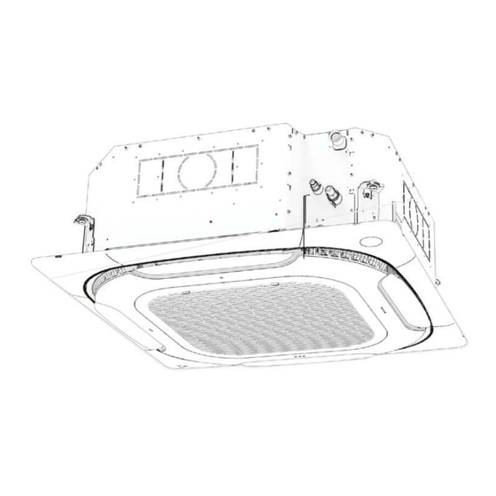
- Page 21 Piezas Descripción de piezas Panel (opcional) Salida de aire Entrada de aire fresco Tubería de desagüe Tubería de líquido *Cable de alimentación y Tubería de gas *Cable de conexión cable de tierra Controlador con cable Controlador remoto Orificio de acceso (opcional) (opcional) Comprobación del conjunto de la cubierta de agua/nivel de...
-
Page 22: Dimensiones Del Producto
Dimensiones del (Unidad: mm) producto 4-M4 (Entrada de aire fresco) 122,5 950 (con panel) Salida de aire lateral (disponible para los cuatro lados) Instalación de los (diámetro interno) suspensores Tubería de desagüe (diámetro externo) E: Conectar a las tuberías de refrigerante (lado del líquido) Tuerca hexagonal (para ajustar el nivel) - Page 23 Materiales de instalación Accesorios Lista de accesorios Tuerca de latón × 2 Brida sujetacables × Tubo de aislamiento Cartón × 1 y del Propietario × 1 térmico × 2 Se utiliza para determinar la Se utiliza para el aislamiento la IDU de la tubería de conexión manguera de desagüe a la y la anticondensación en las...
- Page 24 Accesorios adquiridos localmente Lista de accesorios Tornillo de expansión (M10) × Tubo de cobre Tubo de descarga de agua Tubo de aislamiento Perno de elevación (M10) de PVC térmico × 4 Se utiliza para conectar el Se utiliza para drenar el Se utiliza para evitar la agua condensada de la condensación en las...
-
Page 25: Preparativos Antes De La Instalación
Preparativos antes de la instalación Comprobación de desembalaje Antes de la instalación, compruebe que los materiales de embalaje están El punto rojo en buen estado, que los accesorios que acompañan al producto están sobresale completos, que el equipo de aire acondicionado está intacto y que las Sellado superficies del intercambiador de calor y otras piezas no están desgastadas. - Page 26 Determinar las posiciones de la abertura del techo, la unidad y los pernos de elevación. Corte un orificio con un tamaño de 910 mm × 910 mm (Unidad: mm) según el contorno del cartón de montaje. Corte con la forma del cartón de montaje Orificio del perno de...
- Page 27 Cuando instale el aire acondicionado en un techo nuevo, fije un trozo de cartón al cuerpo principal del aire acondicionado instalado como referencia para determinar el tamaño, la ubicación y el centro de la abertura del techo. [ Precaución ] Ajuste de manera uniforme las cuatro tuercas hexagonales para asegurarse de que el cuerpo principal del aire acondicionado esté...
- Page 28 Instalación de los pernos de elevación [ Nota ] Se utilizan pernos de acero al carbono de alta calidad (galvanizados o con otra pintura antioxidante aplicada) o pernos de acero inoxidable. La forma en que se debe tratar el techo variará con el tipo de construcción. Para medidas específicas, consulte a los ingenieros de construcción y rehabilitación.
- Page 29 Determine la ubicación de los pernos de elevación según los orificios para los pernos de elevación en las cuatro esquinas del cartón de montaje. a. Taladre cuatro orificios con un diámetro de 12 mm y una profundidad de 50–55 mm en el techado conforme a la posición especificada y, a continuación, incruste los ganchos de expansión.
- Page 30 Cuatro unidades con funciones de aire fresco, antes de instalar las IDU:1. utilice alicates diagonales para retirar el orificio ciego de la unidad de aire fresco en un lado de la unidad con anticipación. Instale una brida de aire fresco en la unidad de aire fresco y fíjela con los tornillos de conexión para la brida. 2. Utilice un cuchillo para eliminar el bloqueo de aire fresco de la espuma de la bandeja de drenaje.
- Page 31 Nuevas salas y nuevos techos Para la instalación de los pernos de elevación, se puede incrustar un gancho en la nueva sala. Asegúrese de que el gancho pueda soportar 4 veces el peso de la IDU y que no se afloje debido a la contracción del hormigón.
- Page 32 Instalación del panel Retire la rejilla de entrada de aire Presione las dos abrazaderas de la rejilla al mismo tiempo para levantarla. Hebilla auxiliar Panel de visualización (interior) Abrazadera de rejilla Panel de decoración Lama Rejilla de entrada de aire Placa de cubierta decorativa para esquina Levante la rejilla de entrada de aire aproximadamente 45°...
- Page 33 Instalación del panel Alinee el panel de decoración con la dirección de la IDU: el siguiente texto está grabado en el panel: “Lado de la tubería” y “Lado del drenaje”. Gire el panel de decoración para alinear la dirección grabada como "Lado de las tuberías" con la dirección de las tuberías de refrigerante de la IDU.
-
Page 34: Instalación Del Filtro
El techo deberá tener suficiente resistencia para garantizar que el panel se pueda ajustar firmemente en el techo sin que queden huecos. Si el techo no es lo suficientemente resistente, añada un refuerzo. (Consulte la siguiente figura) Refuerzo Techo No tire del panel de visualización ni de su cable de conexión durante la instalación; de lo contrario, podría producirse una avería. - Page 35 Preste atención a la dirección del filtro primario G3, incluyendo la dirección del flujo de aire y la dirección del soporte de montaje. El lado de la malla metálica está cerca del ventilador. El soporte debe colocarse tal como se muestra a continuación para que el filtro pueda extraerse fácilmente. Los filtros G3 y F6 necesitan soportes de montaje, que deben fijarse en la rejilla de entrada de aire con ocho tornillos de 3,9*10.
- Page 36 Instalación de la rejilla de entrada de aire Incline la rejilla de entrada de aire 45° e inserte los ganchos de suspensión en los orificios de los ganchos situados alrededor de la entrada del aire de retorno del panel de decoración. La rejilla de entrada de aire puede instalarse en cuatro direcciones alrededor de la entrada del aire de retorno.
- Page 37 Instalar la placa decorativa para las esquinas y la placa protectora de la pantalla Fije la eslinga de seguridad en la placa de cubierta decorativa para las esquinas en el panel de decoración. No sujete la eslinga de seguridad al encajar la placa de cubierta Método de instalación de la eslinga de seguridad...
- Page 38 Instalación de las tuberías de conexión de refrigerante Requisitos de longitud y diferencia de nivel para las conexiones de tuberías de la IDU y la ODU Las diferentes ODU tienen diferentes requisitos de longitud y de diferencias de nivel para las tuberías. Consulte el Manual de instalación y del Propietario que se adjunta con la ODU.
- Page 39 Pasos para la conexión de la tubería Mida la longitud necesaria de la tubería de conexión. Prepare la tubería de conexión siguiendo el siguiente método (véase "Conexión de la tubería" para más detalles). Conecte primero la IDU y, a continuación, la ODU. Antes de apretar la tuerca cónica, aplique aceite de refrigeración en la superficie interior y exterior del abocardado de la tubería (para este modelo, debe utilizar aceite de refrigeración compatible con el refrigerante) y gírela 3 ó...
- Page 40 Soldadura de tuberías Al soldar las tuberías, llénelas con nitrógeno. Caliente primero de forma uniforme los tubos interiores y luego los exteriores, y llene las juntas con material de soldadura. [ Precaución ] Cuando sea necesario llenar la tubería con nitrógeno durante la soldadura, la presión debe mantenerse a 0,02 MPa utilizando una válvula de alivio de presión.
- Page 41 La tuerca protectora es una pieza de un solo uso, no se puede reutilizar. En caso de que se retire, debe sustitu- irse por una nueva. (Sólo para la norma IEC 60335-2-40: 2018) Manilla Barra Barra Horquilla Cono Tubo de cobre Manija de la abrazadera Marca de flecha roja Tuerca protectora Tubos de la unidad interior...
-
Page 42: Detección De Fugas
Bombeo de vacío Válvula de retención Conecte la tubería de refrigerante a las tuberías de gas y de líquido de la ODU, y utilice una bomba de vacío para evacuar las tuberías de gas y de líquido de la ODU al mismo tiempo. No utilice el refrigerante que contiene la Manómetro de alta presión ODU para realizar el vacío. -
Page 43: Instalación De La Tubería De Desagüe
Instalación de la tubería de desagüe [ Precaución ] Antes de instalar la tubería de condensado, determine su dirección y elevación para evitar la intersección con otras tuberías y asegurar que la pendiente sea lisa y recta. El punto más alto de la tubería de desagüe debe estar equipado con un puerto de descarga para garantizar una descarga suave del agua de condensación, y el puerto de descarga debe estar orientado hacia abajo para evitar que entre suciedad en la tubería. - Page 44 Las tuberías de desagüe de la unidad (especialmente la parte interior) deben estar envueltas de forma uniforme con tubos de aislamiento térmico y sujetas con bridas para evitar la entrada de aire y la producción de agua condensada. Brida sujetacables Tubería de desagüe Tubo de aislamiento térmico Para evitar que el agua vuelva a entrar en el aire acondicionado cuando éste deje de funcionar, evite instalar...
- Page 45 El extremo de la tubería de desagüe debe estar a más de 50 mm del suelo o de la base de la ranura de descarga de agua. Además, no lo sumerja en agua. Para descargar el agua condensada directamente en una zanja, el tubo de descarga de agua debe doblarse hacia arriba para formar un tapón de agua en forma de U a fin de evitar que los olores entren en la sala a través del tubo de descarga de agua.
- Page 46 Prueba de descarga de agua Antes de la prueba, asegúrese de que la tubería de descarga de agua esté lisa, y verifique que cada conexión esté bien sellada. Realice la prueba de descarga de agua en una sala nueva antes de enlucir el techo.
-
Page 47: Conexiones Eléctricas
Conexiones eléctricas [Peligro] Antes de realizar cualquier trabajo eléctrico debe cortarse la alimentación eléctrica. No realice trabajos eléctricos con la alimentación conectada; de lo contrario, podrían producirse lesiones personales graves. La unidad de aire acondicionado debe estar conectada a tierra de forma fiable y debe cumplir con los requisitos del país/región local. -
Page 48: Características Eléctricas
Características eléctricas Especificaciones eléctricas de la IDU Entrada de Potencia de la unidad Frecuencia Tensión potencia (kW) (Hz) 0,51 0,41 0,51 0,41 0,59 0,47 0,59 0,47 0,94 0,75 220~240 1,05 0,84 1,09 0,87 0,95 0,76 10,0 1,18 0,94 11,2 1,41 1,13 14,0 Notas:... - Page 49 Diagrama esquemático de los principales bloques de terminales de la placa de control principal CN22 CN10 CN18 CN55 Terminales de la señal Terminales de la placa adaptadora M1 M2 D1(X) D2(Y) del interruptor remoto del módulo de funciones Terminales del cable de Terminales de la línea de comunicación Terminales del módulo Terminales de...
- Page 50 Entrada de corriente débil Entrada de corriente fuerte Línea de Cable de comunicación y alimentación y cable de tierra, cable de tierra, etc. etc.. [ Precaución ] Los cables de corriente fuerte y débil deben estar separados. La salida de la señal de alarma, la esterilización por corriente fuerte, el interruptor remoto y la tarjeta de expansión de funciones son funciones personalizadas u opcionales.
- Page 51 [ Precaución ] No una ni empalme el cable de alimentación. La unión y el empalme del cable de alimentación pueden hacer que éste se caliente, provocando un incendio. El cable de alimentación debe engarzarse de forma Si no logra crimpar el bloque de terminales circular y aislado debido a las limitaciones del lugar, conecte los cables de fiable utilizando un bloque de terminales circular alimentación del mismo diámetro a ambos lados del bloque de...
- Page 52 2. Conexión del sistema del cable de alimentación La conexión del sistema de cables de alimentación depende de las formas de comunicación entre la IDU y la ODU. Las IDU están provistas de una fuente de alimentación uniforme*, que se cablea de la siguiente manera: 2.
- Page 53 Conexión de la línea de comunicación 1. Selección del método de comunicación para las IDU Preste atención al tipo de IDU que ha adquirido antes de conectar las líneas de comunicación. Consulte la siguiente tabla para seleccionar un método de comunicación adecuado. Método de comunicación Observaciones Tipo de IDU...
- Page 54 [ Precaución ] Seleccione la línea de comunicación según los requisitos de la tabla de referencia anterior. Utilice cables blindados para la comunicación en caso de presencia de un fuerte magnetismo o interferencias. El cableado in situ debe cumplir con la normativa local pertinente del país/región y debe ser realizado por profesionales.
- Page 55 3. Comunicación de IDU y ODU Comunicación P/Q Unidad individual: utilice un cable blindado para la comunicación P/Q y conecte a tierra correctamente la capa de blindaje. Los puertos P y Q se encuentran en el bloque de terminales “CN6” de la placa de control principal.
- Page 56 Comunicación P/Q/E Si algunas de las IDU del mismo sistema de refrigeración no son de la serie JR8, es necesario conectar "P", "Q" y "E" para la comunicación P/Q/E. Unidad individual: utilice un cable blindado para la comunicación P/Q/E y conecte a tierra correctamente la capa de blindaje.
- Page 57 [ Precaución ] Cuando se utiliza la comunicación P/Q o P/Q/E, las IDU deben recibir alimentación de manera uniforme. Utilice únicamente cables blindados para la comunicación P/Q o P/Q/E. De lo contrario, la comunicación de IDU y ODU puede verse afectada. Es necesario añadir un resistor de adaptación a la última IDU en la comunicación PQ (en la bolsa de accesorios de la ODU).
- Page 58 5. Conexión de la línea de comunicación D1D2 (limitado a la configuración de ODU y del sistema) Obtener las funciones de uno a varios y de dos a varios del controlador con cable de la IDU a través de la comunicación D1D2 (un máximo de 16) La comunicación D1D2 es una comunicación 485.
- Page 59 Conexión de la placa externa (se limita a la ODU y a la configuración del sistema) La placa externa es un módulo de conexión fuera de la placa de control principal que incluye un panel de visualización, una placa adaptadora de módulos de funciones y las tarjetas de expansión de funciones 1 y 2 opcionales. 1.
- Page 60 Volver a cerrar la tapa de la caja de control eléctrico Extienda los cables de conexión y póngalos en posición horizontal; vuelva a cerrar la tapa de la caja de control eléctrico. [ Precaución ] No cubra la caja de control eléctrico durante el encendido. Cuando cubra la caja de control eléctrico, coloque los cables con cuidado y no sujete los cables de conexión en la tapa de la caja de control eléctrico.
- Page 61 Control de aplicaciones Códigos de error y definiciones En las siguientes circunstancias (se excluyen los fallos de advertencia), detenga el aire acondicionado inmediatamente, desconecte el interruptor de alimentación y póngase en contacto con el centro local de atención al cliente del aire acondicionado.
- Page 62 Error Pantalla digital Código de error Comunicación anormal entre la IDU y la ODU Comunicación anormal entre la placa de control principal de la IDU y la placa de accionamiento del ventilador Comunicación anormal entre la IDU y el controlador con cable Comunicación anormal entre la IDU y el kit Wi-Fi Comunicación anormal entre la placa de control principal de la IDU y la placa de visualización...
- Page 63 Error Código de error Pantalla digital El sensor de temperatura de la sala integrado en el controlador con cable se cortocircuita o se desconecta El sensor de temperatura inalámbrico se cortocircuita o se desconecta El sensor externo de temperatura de la sala se cortocircuita o se desconecta Tcp (sensor de temperatura del aire fresco preenfriado) se cortocircuita o se desconecta Tph (sensor de temperatura del aire fresco precalentado) se cortocircuita o se...
- Page 64 Error Pantalla digital Código de error Fallo de baja tensión del bus Fallo de alta tensión del bus Error de sesgo de muestra de corriente de fase El motor y la IDU no se corresponden El IPM y la IDU no se corresponden Fallo de arranque del motor Protección de bloqueo del motor Error de ajuste del modo de control de velocidad...
- Page 65 Descripción de la comprobación puntual Utilice el controlador con cable de comunicación bidirec- cional para activar la función de comprobación puntual en los siguientes pasos: N.º de 1. En la página principal, mantenga pulsados " " y " " comprobación durante 2seg.
- Page 66 Interfaz de configuración de parámetros Mantener pulsado Botones de Botón Tecla OK durante 3seg. para selección BACK acceder a la página Valor Nombre del Rango del parámetro Observaciones Código del parámetro predeterminado parámetro La IDU establece el valor Presión estática Presión estática externa de de presión estática externa de la...
-
Page 67: Prueba De Funcionamiento
Prueba de funcionamiento Antes de la prueba de funcionamiento, asegúrese de que: • Las IDU y la ODU están instaladas correctamente. • Las tuberías son correctas y se ha comprobado que el sistema de tuberías de refrigerante no presenta fugas. •... - Page 68 Inspección después de la instalación Para asegurar un ambiente interior confortable, por favor repase la lista para comprobar si la instalación del Resultado de la Elementos de comprobación Criterios de comprobación comprobación (aprobado/no aprobado) ¿Están las IDU y las ODU instaladas de forma El aire acondicionado no se cae ni vibra, segura? y no hace ruido.
-
Page 69: Advertencia De Seguridad
Limpieza, Mantenimiento y Servicio Posventa Advertencia de seguridad [ Advertencia ] Por razones de seguridad, apague siempre el aire acondicionado y desconecte la corriente antes de limpiarlo. No desmonte ni repare el aire acondicionado usted mismo; de lo contrario, podría provocar un incendio u otros peligros. - Page 70 Diagrama de procedimiento Retire la rejilla de entrada de aire Presione las dos abrazaderas de la rejilla al mismo tiempo para levantarla. Levante la rejilla de entrada de aire aproximadamente 45° y retire la rejilla. Hebilla auxiliar Panel de visualización (interior) 45°...
- Page 71 Limpieza de las salidas de aire y los paneles exteriores Limpie la salida de aire y el panel con un paño Si una mancha es difícil de eliminar, límpiela seco. con agua limpia o detergente neutro. [ Precaución ] No use gasolina, benceno, agentes volátiles, polvo de descontaminación o insecticidas líquidos. De lo contrario, la salida de aire o el panel podrían decolorarse o deformarse.
- Page 72 Mantenimiento de las piezas convencionales Mantenimiento de la placa principal de control electrónico y del sensor de temperatura de la sala Abrir la rejilla de entrada de aire. Presione las dos abrazaderas de la rejilla de entrada de aire hacia la izquierda y abra la rejilla hacia abajo.
- Page 73 Mantenimiento del ventilador Siga los pasos anteriores para extraer la placa de control principal y el soporte de la placa de control principal. Afloje los cuatro tornillos de la derecha y retire la Vuelva a colocar el ventilador después de quitar las tuercas del centro del ventilador y la abrazadera del chapa metálica de la caja de control eléctrico;...
- Page 74 Mantenimiento del evaporador y del sensor de temperatura Siga los pasos anteriores para extraer la rejilla de entrada de aire (recupere el refrigerante antes de reparar el evaporador). Extraiga los paneles de decoración de las cuatro Afloje los tornillos de bloqueo de las cuatro esquinas y retire esquinas.
- Page 75 En primer lugar, retire los tornillos (tres) que conectan la caja de control eléctrico y la placa de sellado y, a continuación, retire los tornillos (cuatro) de la abrazadera del cable y el tornillo (uno) de la caja de control eléctrico. Conexión entre el conjunto de la caja de control eléctrico y la placa de sellado...
- Page 76 Retire las tuberías de conexión de la IDU y la Después de quitar los tres tornillos de fijación, ODU y desatornille los dos tornillos de la placa retire la placa de fijación del evaporador. A de sellado de las tuberías para retirar la placa. continuación, retire el evaporador.
- Page 77 Mantenimiento de la bomba de agua Siga los pasos anteriores para retirar la rejilla de entrada de aire, la tapa de la caja de control eléctrico, los cables, el panel, la caja de control eléctrico, el anillo guía de aire y la bandeja de drenaje. Desconecte la tubería de desagüe.
- Page 79 Preface De a r us ers , Thank you for purchasing and using our product. Please read this manual carefully before you install, use, maintain or troubleshoot this product so that you can familiarize yourself with the product and use it correctly. For ODUs or other IDUs, please refer to the applicable installation &...
-
Page 81: Safety Warning
Please thoroughly read and ensure that you fully understand the safety precautions (including the signs and symbols) in this manual, Safety Warning and follow relevant instructions during use to prevent damage to health or property. Explanation of symbols displayed on the unit This symbol shows that this appliance used a flammable refrigerant. -
Page 82: Safety Precautions
Warning contents Ensure Proper Grounding Professional Only Prohibition signs No Flammable Materials No Open Fire No Acid or Alkali Materials No Strong Current Safety Precautions Danger During thunderstorms, disconnect the main power switch. Otherwise, lightning may damage the unit. In the event of refrigerant leakage, smoking and open flames are prohibited. Disconnect the main power switch immediately, open windows to allow ventilation, keep away from the leakage point, and contact your local dealer or technical support to request a professional repair. - Page 83 Electric Safety Requirements Warning The air conditioner shall be installed according to the local wiring specifications. Wiring work must be completed by qualified electricians. All wiring work must comply with electrical safety specifications. The air conditioner must be well grounded. Specifically, the main switch of the air conditioner must have a reliable grounding cable.
- Page 84 non-sparking, adequately sealed or intrinsically safe. If any hot work is to be conducted on the refrigeration equipment or any associated parts, appropriate fire extinguishing equipment shall be available to hand. Have a dry powder or CO2 fire extinguisher adjacent to the charging area.
- Page 85 When breaking into the refrigerant circuit to make repairs – or for any other purpose – conventional procedures shall be used. However, it is important that best practice is followed. Since flammability is a consideration. The following procedure shall be adhered to: The refrigerant charge shall be recovered into the correct recovery cylinders.
- Page 86 The recovered refrigerant shall be returned to the refrigerant supplier in the correct recovery cylinder, and the relevant Waste Transfer Note arranged. Do not mix refrigerants in recovery units and especially not in cylinders. If compressors or compressor oils are to be removed, ensure that they have been evacuated to an acceptable level to make certain that flammable refrigerant does not remain within the lubricant.
-
Page 87: Operation Precautions
Operation Operation Precautions Warning If the unit will be not used for a long time, disconnect the main power switch. Otherwise, an accident may occur. The installation height of the air conditioner shall be at least 2.5m above the ground to avoid the following risks: Running parts may cause harm to you or transmission assemblies may become damaged. -
Page 88: Optimum Operation
Disposal: Do not dispose of this product as unsorted municipal waste. Collection of such waste separately for special treatment is necessary. Do not dispose of electrical appliances as unsorted municipal waste, use separate collection facilities. If electrical appliances are disposed of in landfills or dumps, hazardous substances can leak into the groundwater and get into the food chain, damaging your health and well-being. -
Page 89: Operating Range
Operating Range To maintain good performance, operate the air conditioner under the following temperature conditions: Indoor 16~32°C temperature Cooling Indoor (When the humidity exceeds 80%, long-time operation of the IDU may cause dew humidity condensation on the surface of the IDU or generate mist-like cold air from the air outlet.) Indoor Heating 15~30°C... - Page 90 Normal Phenomena that Are Not Air Conditioner Faults The following phenomena are normal during operation of the air conditioner. They can be solved according to the instructions below or do not need to be solved. The IDU emits white mist 1.
-
Page 91: Display Panel
In winter, the outdoor temperature is low, and heating effects may be decreased 1. During the heating operation of the heat pump type air conditioner, the air conditioner absorbs heat from the outdoor air and releases it to heat the indoor air. This is the heat pump heating principle of the air conditioner. -
Page 92: Installation Precautions
Installation Carefully read this manual before installing the IDU. Installation Precautions Qualification and Safety Regulation Requirements Warning Please carry out the installation according to local standards. Ask your local dealer or professionals to install the product. This unit must be installed by professional technicians with relevant specialized knowledge. Users MAY NOT install the unit themselves;... - Page 93 Before and after installation, exposing the unit to water or moisture will cause electrical short circuit. Do not store the unit in a humid basement or expose it to rain or water. Make sure the installation base and lifting are robust and reliable; Insecure installation of the base may cause the air conditioner to fall, leading to an accident.
- Page 94 Precautions for Carrying and Lifting the Air Conditioner Before carrying the air conditioner, determine the route that will be used to move it to the installation site. Do not unseal the air conditioner until it is moved to the installation site. When unpacking and moving the air conditioner, you must hold the hanger seat and do not apply force to other parts, especially the refrigerant piping, drainage pipe and plastic accessories, so as to avoid damaging the air conditioner and causing personal injury.
- Page 95 Recommended Installation Sites It is recommended to install the air conditioner according to the design drawing of the HVAC engineer. The selection principle for the installation site is as follows: Ensure that the airflow in and out of the IDU is reasonably organized to form an air circulation in the room. Ensure IDU maintenance space.
- Page 96 Avoid installation in narrow spaces or where there are more stringent noise requirements. The IDU needs to be installed at a position greater than 2.5m and less than 4.5m from the ground. Condensate water can be discharged smoothly. The length of the piping between the indoor and ODUs is within the permitted range. Refer to the Installation &...
- Page 97 Recommended Installation Sites Crowded places such as living rooms and offices The air outlet must not face the areas where people frequently spend time, such as sofas and coffee tables. Instead, let the airflow exit from the side for enhanced comfort. Air outlets at corners can be blocked with optional accessories (which can be found in the packaging material) Air outlet blocked...
- Page 98 Parts Part Description Panel (optional) Air outlet Fresh air inlet Drainage pipe Liquid pipe Gas pipe *Power cable and ground wire *Connection wire Wired controller (optional) Remote controller (optional) Access hole *Communication line Water cover assembly/water level, water level switch check Expanded air inlet/outlet * To be purchased separately on site.
-
Page 99: Product Dimensions
Product Dimensions (Unit: mm) 4-M4 (Fresh air inlet) 122.5 950 (with panel) Side air outlet (available for four sides) Suspender installation 23 (internal diameter) Drainage pipe 25 (OD) E: Connect to refrigerant piping (liquid side) Hex nut (to adjust level) F: Connect to refrigerant piping (gas side) Ceiling... -
Page 100: Installation Materials
Installation Materials Accessories List of accessories Installation & Owner's Brass nut X 2 Cable tie X 4 Thermal insulation Cardboard X 1 Manual X 1 pipe X 2 Used to determine the IDU Installation Instructions For use in the installation of To tightly secure the drainage Used for insulation and (Make sure to hand it over to... - Page 101 Locally Purchased Accessories List of accessories Expansion screw (M10)X4 Copper pipe PVC water discharge pipe Thermal insulation pipe Lifting bolt (M10)X4 Used to connect the IDU Used to drain the Used to prevent pipe Used to install the IDU. Used to install the IDU. refrigerant system.
-
Page 102: Preparations Before Installation
Preparations Before Installation Unpacking Check Before installation, check whether the packing materials are in The red dot bulges good condition, whether the accessories that come with the product Sealing are complete, whether the air conditioner is intact, and whether the surfaces of the heat exchanger and other parts are worn. - Page 103 Determine the positions of the ceiling opening, the unit and the lifting bolts. Cut a hole with a size of 910mm x 910mm according to the (Unit: mm) outline of the mounting cardboard. Shape cutting of the mounting cardboard Lifting bolt hole 4- 12 788 (suspender distance) 798 (cardboard fixing hole) 840 (IDU size)
-
Page 104: Idu Installation
When installing the air conditioner on a new ceiling, affix a piece of cardboard to the main body of the installed air conditioner for reference to determine the size, location, and center of the ceiling opening. Caution Evenly adjust the four hex nuts to make sure that the main body of the air conditioner is level. When the air conditioner is to be fixed onto the ceiling with a frame: The horizontal distance of the overlapping part of the ceiling and decoration panel must be more than 10mm. - Page 105 Installation of Lifting Bolts Note High-quality carbon steel bolts (galvanized or with other anti-rust paint applied) or stainless steel bolts are used. How the ceiling is treated will differ with the type of building. For specific measures, please consult the building and renovation engineers.
- Page 106 Determine the location of lifting bolts according to the lifting bolt hole at the four corners of the mounting cardboard. a. Drill four holes with a diameter of 12mm and a depth of 50–55mm on the roof according to the specified position, and then embed expansion hooks.
- Page 107 For units with fresh air functions, before installing IDUs: 1. Use diagonal pliers to remove the knockout at the fresh air unit at one side of the unit in advance. Install a fresh air flange at the fresh air unit and secure it with the flange connecting screws.
- Page 108 New rooms and new ceilings For the installation of lifting bolts, a hook can be embedded in the new room. Make sure the hook can withstand 4 times the weight of the IDU and will not loosen due to the shrinkage of the concrete. After the main body is lifted, fix the mounting cardboard on the air conditioner unit with M6×16 screws to predetermine the size and position of the ceiling opening.
-
Page 109: Panel Installation
Panel Installation Remove the air inlet grille Press the two grille clamps at the same time to lift it. Auxiliary buckle Display panel (inner) Grille clamp Decoration panel Louver Air inlet grille Decorative cover plate for corner Raise the air inlet grille to about 45° and remove the grille. 45°... - Page 110 Install the panel Align the decoration panel with the IDU direction: The following text is engraved on the decoration panel: "Piping side" and "Drainage side". Rotate the decoration panel to align the direction engraved with "Piping side" with the refrigerant piping direction of the IDU. Due to product updates, the current drain side is the same as the piping side, as shown in the two serial numbers in the figure below.
- Page 111 The ceiling shall have sufficient strength to ensure that the panel and the ceiling can be tightly fitted without gap. If the ceiling is not strong enough, add a stiffener. (See the figure below) Stiffener Ceiling Do not pull the display panel and its connecting cable during installation; otherwise a fault could occur.
- Page 112 Pay attention to the direction of the G3 primary filter, including the airflow direction and mounting bracket direction. The wire mesh side is near the fan. The bracket should be placed as shown below, so that the filter can be pulled out easily. The G3 and F6 filters need mounting brackets, which are to be fixed at the air inlet grille using eight 3.9*10 screws.
- Page 113 Install the air inlet grille Tilt the air inlet grille by 45°, and insert the suspension hooks into the hook holes around the return air inlet of the decoration panel. The air inlet grille can be installed at four directions around the return air inlet. But only two directions provide structures to install the safety sling.
- Page 114 Install the decorative cover plate for the corners and the display cover plate Fix the safety sling on the decorative cover plate for corner on the decoration panel. Do not clamp the safety sling when snap-fitting the cover plate Safety sling installation method Snap-fit the decorative cover plate for corner: There are three buckles on the decorative cover plate.
- Page 115 Refrigerant Connecting Piping Installation Length and Level Difference Requirements for the Pipe Connections of IDU and ODU Different ODUs have different requirements for length and level differences for the piping. Refer to the Installation & Owner's Manual attached with the ODU. Warning During the installation of the connecting pipes, do not allow air, dust, and other debris to penetrate the piping system, and make sure the interior of the pipes is dry.
-
Page 116: Pipe Connection
Pipe Connection Steps Measure the required length of the connecting pipe. Make the connecting pipe using the following method (see "Pipe Connection" for details). Connect the IDU first, then connect the ODU. Before tightening the flare nut, apply refrigeration oil on the inner and outer surface of the pipe flare (you must use refrigeration oil compatible with the refrigerant for this model), and turn it 3 or 4 turns by hand to tighten it. - Page 117 Brazing pipes When brazing pipes, fill the pipes with nitrogen. First evenly heat the inner pipes, then the outer pipes, and fill the joints with welding material. Caution When it is necessary to fill the piping with nitrogen during welding, the pressure must be kept at 0.02MPa using a pressure relief valve.
- Page 118 The protective nut is a one-time part, it can not be reused. In case it is removed, it should be replaced with a new one.(For IEC 60335-2-40: 2018 only) Handle Yoke Cone Copper pipe Clamp handle Red arrow mark Protective nut Indoor unit tubing Flare nut Pipings...
-
Page 119: Vacuum Pumping
Vacuum Pumping Check valve Connect the refrigerant piping to the gas and liquid pipes of the ODU, and use a vacuum pump to evacuate the gas and liquid pipes of the ODU at the same time. Do not use the refrigerant enclosed High pressure gauge in the ODU for vacuuming. -
Page 120: Drainage Pipe Installation
Drainage Pipe Installation Caution Before installation of the condensate pipeline, determine its direction and elevation to avoid intersection with other pipelines to ensure that the slope is smooth and straight. The highest point of the drainage pipe should be equipped with a discharge port to ensure the smooth discharge of condensate water, and the discharge port must face downwards to prevent dirt from entering the pipe. - Page 121 The drainage pipes of the unit (especially the indoor part) must be evenly wrapped with thermal insulation pipes and fastened with cable ties to prevent air from entering and producing condensate water. Cable tie Drainage pipe Thermal insulation pipe To prevent water from flowing back into the air conditioner when it stops running, avoid installing the drainage pipe in a way that slopes upwards for a long distance.
- Page 122 The end of the drainage pipe must be more than 50mm above the ground or from the base of the water discharge slot. In addition, do not submerge it in water. To discharge the condensed water directly into a ditch, the water discharge pipe must bend upwards to form a U-shaped water plug to stop odors from entering the room via the water discharge pipe.
- Page 123 Water Discharge Test Before the test, make sure that the water discharge pipeline is smooth, and check that each connection is properly sealed. Conduct the water discharge test in a new room before the ceiling is plastered. Drainage pipe Test water outlet Master unit The drainage pipes for IDUs may use a PVC pipe Water cover...
-
Page 124: Electrical Connection
Electrical Connection Warning The power supply must be cut off before any electrical work is carried out. Do not conduct electrical work when the power is on; otherwise, it may cause serious personal injury. The air conditioning unit must be grounded reliably and must meet the requirements of the local country/region. -
Page 125: Electrical Characteristics
Electrical Characteristics Electric specifications of the IDU Unit power power Frequency Voltage (kW) input (Hz) 0.51 0.41 0.51 0.41 0.59 0.47 0.59 0.47 0.94 0.75 220~240 1.05 0.84 1.09 0.87 0.95 0.76 10.0 1.18 0.94 11.2 1.41 1.13 14.0 Notes: MCA: Min. - Page 126 Schematic diagram of the main terminal blocks of main control board CN22 CN10 CN18 CN55 Terminals of function Terminals of remote M1 M2 D1(X) D2(Y) module adapter board switch signal Power cable and earth Terminals of communication line Terminals of strong Alarm signal line terminals current sterilization...
- Page 127 Weak current inlet Strong current inlet Communication Power cable and line and ground ground wire, etc. wire, etc. Caution The strong and weak current wires must be separated. Alarm signal output, strong current sterilization, remote switch, and expansion board are custom or optional functions.
- Page 128 Caution Do not bond and connect the power cable. Bonding and connecting the power cable may cause it to heat up, resulting in a fire. The power cable must be crimped reliably using an If it fails to crimp the insulated circular terminal block due to insulated circular terminal block, and then connected on-site limitations, connect the power cables of the same to the power supply terminal of the IDU, as shown in...
- Page 129 2. Power cable system connection Power cable system connection depends on the forms of communication between the IDU and ODU. IDUs are provided with uniform power supply*, which are wired as follows: 1. P/Q communication: Power supply for IDU Communication wire ×...
- Page 130 Communication line connection 1. Selection of communication method for IDUs IDU type Optional communication method Remarks between IDUs and ODU 1. The IDUs need to be powered uniformly. Are all the 2. The communication cables must be connected RS-485 (PQ) IDUs in in serial.
- Page 131 Caution Please select the communication line according to the requirements in the above reference table. Use shielded cables for communication when strong magnetism or interference is present. On-site wiring must comply with the relevant regulations of the local country/region and must be completed by professionals.
- Page 132 System: The maximum total length of the P/Q communication cable of the IDU and ODU can be up to 1200m, and can be connected in serial, as shown in the figure below: Power supply for IDU × × Communication wire Circuit breaker Power cable Distribution box...
- Page 133 Caution When P/Q or P/Q/E communication is used, the IDUs need to be powered uniformly. Use only shielded cables for P/Q or P/Q/E communication. Otherwise, the IDU and ODU communication may be affected. A matching resistor needs to be added to the last IDU on the PQ (in the accessory bag of the ODU). 4.
- Page 134 5. D1D2 communication line connection (limited to ODU and system configuration) Achieving one-to-multiple and two-to-multiple functions of the IDU wired controller through D1D2 communication (a maximum of 16 sets) D1D2 communication is 485 communication. The one-to-more and two-to-more functions of the IDU wired controller can be achieved through D1D2 communication, as shown in the figure below: IDU 2# IDU 16#...
- Page 135 External board connection (limited to ODU and system configuration) The external board is a connection module outside the main control board, including a Switch module, and 1# and 2# Expansion boards . Display panel connection The display panel is connected to the main control board through a 4-core cable, and is connected to the "CN30"...
- Page 136 Reclose the electric control box cover Straighten out the connecting wires and lay them flat, and close the electric control box cover again. Caution Do not cover the electric control box during power-on. When covering the electric control box, arrange the cables carefully and do not clip the connecting wires on the electric control box cover.
-
Page 137: Application Control
Application Control Error Codes and Definitions In the following circumstances (warning failures excluded), please stop the air conditioner immediately, cut off the power switch and contact the local air conditioner customer service center. The error code is displayed on the display panel and the wired controller display. Error Error code Digital display... - Page 138 Error Error code Digital display Abnormal communication between the IDU and ODU Abnormal communication between the IDU main control board and fan drive board Abnormal communication between the IDU and wired controller Abnormal communication between the IDU and Wi-Fi Kit Abnormal communication between the IDU main control board and display board Abnormal communication between the AHU Kit slave unit and master unit Number of AHU Kits is not the same as the set number...
- Page 139 Error Error code Digital display The built-in room temperature sensor of the wired controller short-circuits or cuts off The wireless temperature sensor short-circuits or cuts off The external room temperature sensor short-circuits or cuts off Tcp (pre-cooled fresh air temperature sensor) short-circuits or cuts off Tph (pre-heated fresh air temperature sensor) short-circuits or cuts off TA (outlet air temperature sensor) short-circuits or cuts off Outlet air humidity sensor fault...
- Page 140 Error Error code Digital display Low bus voltage fault High bus voltage fault Phase current sample bias error Motor and IDU are unmatched The IPM and IDU are unmatched Motor startup failure Motor blocking protection Speed control mode setting error Phase lack protection of motor Operating Status Codes and Definitions (Non-Error) Definition...
- Page 141 Spot Check Description Use the bi-directional communication wired controller to activate the spot check function in the following steps: 1. On the main page, hold " " and " " for 2s to enter Check No. the query page. The ODU displays u00-u03, the IDU displays n00-n63 (the last two digits show the IDU Spot check address), and the wired controller displays CC.
- Page 142 Parameter setting interface Hold for 3s to Selection BACK OK key enter the page buttons button Parameter code Parameter name Parameter range Default value Remarks The IDU sets the Unit external Unit external static pressure: selected corresponding static pressure 00/01/02/03/04/05/~/19 static pressure value FF.
- Page 143 Test Run Before the Test Run, Make Sure That IDUs and the ODU are properly installed. The piping is correct, and the refrigerant piping system has been checked for leakage. Piping length and the amount of refrigerant charged have been recorded. The wiring is correct and firm without virtual connection issues.
-
Page 144: Inspection After Installation
Inspection After Installation To ensure a comfortable indoor environment, please run down through the list to check whether the installation Check Result Check Item Check Criteria (Pass/Fail) The air conditioner does not fall or Are the IDUs and ODUs securely installed? vibrate, and there is no noise. -
Page 145: Cleaning And Maintenance
Cleaning, Maintenance and After-Sales Service Safety Warning Warning For safety reasons, always turn off the air conditioner and turn off the power before cleaning the air conditioner. Do not disassemble or repair the air conditioner by yourself; otherwise, it may cause fire or other hazards. Only professional service personnel can carry out the maintenance. - Page 146 Procedure diagram Remove the air inlet grille. Press the two grille clamps at the same time to lift it. Raise the air inlet grille to about 45°, and remove the grille. Auxiliary buckle Display panel (inner) 45° Grille clamp Decoration panel Louver Air inlet grille Decorative cover...
-
Page 147: Maintenance
Cleaning Air Outlets and Exterior Panels Wipe the air outlet and panel with a dry cloth. If a stain is hard to remove, clean it with clean water or neutral detergent. Caution Do not use gasoline, benzene, volatile agents, decontamination powder or liquid insecticides. Otherwise, the air outlet or panel may become discolored or deformed. - Page 148 Maintenance of Conventional Parts Maintenance of Electronic Control Main Board and Room Temperature Sensor Open the air inlet grille. Press the two grille clamps of the air inlet grille to the left and open the grille downwards. Raise the air inlet grille to about 45°, and push the grille towards the unit direction to separate the grille from the panel.
- Page 149 Maintenance of Fan Follow the steps above to remove the main control board and the main control board support. Loosen the four screws on the right and remove Replace the fan after removing the nuts at the the sheet metal of the electric control box; loosen center of the fan and the fan clip.
- Page 150 Maintaining the Evaporator and Temperature Sensor Follow the steps above to remove the air inlet grille (recover refrigerant before repairing the evaporator). Loosen the locking screws at four corners and remove Remove the decoration panels at four corners. the hooks at four corners of the panel from the IDU. Take the auxiliary hooks of the panel from the air guide ring to remove the panel.
- Page 151 First remove the screws (three) connecting the electric control box and the sealing plate, and then remove the screws (four) of the wire clip and the screw (one) of the electric control box. Connection between the electric control box assembly and sealing plate Wire clip Screw (three)
- Page 152 Remove the connecting pipes of IDU and ODU After removing three fixing screws, remove the and unscrew the two screws of the sealing evaporator board. Then remove plate of the piping to remove the plate. evaporator. Connecting pipes of the IDU and ODU Screw Screw (two)
- Page 153 Maintenance of Water Pump Follow the steps above to remove the air inlet grille, electric control box cover, wires, panel, electric control box, air guide ring, and drain pan. Unplug the drainage pipe. After removing the two fixing screws, the pump can be taken out for replacement or maintenance. Remove the fixing screws of the water pump and the pump bracket, and remove the water pump and water level switch.
- Page 155 Escanee para ver este manual en otros idiomas y actualizaciones Scan for manual in other languages and further updates Manuel dans d'autres langues et mis à jour Manual em outras línguas e actualizações Toda la documentación del producto Polígono Industrial San Carlos, Complete documents about the product Camino de la Sierra S/N Parcela 11 Documentation plus complète sur le produit...
Need help?
Do you have a question about the VARI CST Series and is the answer not in the manual?
Questions and answers