
Subscribe to Our Youtube Channel
Related Manuals for Ametek JOFRA AMC910


Summary of Contents for Ametek JOFRA AMC910
- Page 1 Reference Manual Advanced Multi-Purpose Calibrator AMETEK JOFRA AMC910 Copyright 2008 AMETEK Denmark A/S...
- Page 2 12-03-2008 126782...
-
Page 3: Table Of Contents
Table of Contents Introduction ................5 1.1 Technical assistance ..............5 1.2 Standard Equipment ..............5 1.3 Options and Accessories .............. 5 1.4 Unpacking ..................6 1.5 Safety Information................. 7 Calibrator Description............10 2.1 Front Panel Overview ..............10 2.2 Primary Input/Output Terminals..........11 2.3 Primary Input/Output Display Controls ........ - Page 4 7.4 RTD Test..................47 7.5 RTD Transmitter ................. 48 7.6 Thermocouple Test..............49 7.7 Thermocouple Transmitter............50 7.8 RTD Indicator................51 7.9 I/I Isolator/Transmitter ..............52 7.10 I/I Isolator/Transmitter ..............53 7.11 Precision Temperature Measurement with STS Probe ....54 LCD and Remote Interface Setup Procedures.....55 Remote Interface ..............55 9.1 Introduction .................
-
Page 5: Introduction
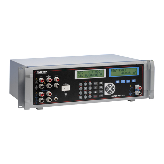
Introduction The AMETEK JOFRA series AMC910 calibrator is an accurate full-featured temperature, pressure and DC calibrator intended for R & D, manufacturing and calibration lab applications. The unit's simple design and ease of operation allow users to quickly familiarize themselves with its operations and features. -
Page 6: Unpacking
Remove the Packing List and verify that all of the listed equipment has been received. If there are any questions about the shipment, please call: Sales & Service Offices: AMETEK Mansfield & Green (North America) Tel: +1 800 527 99 • cal.info@ametek.com AMETEK Singapore Pte. -
Page 7: Safety Information
1.5 Safety Information Symbols Used The following table lists the International Electrical Symbols. Some or all of these symbols may be used on the instrument or in this manual. Symbol Description AC (Alternating Current) AC-DC Battery CE Complies with European Union Directives Double Insulated Electric Shock Fuse... - Page 8 This calibrator must be recycled or disposed of properly (2002/95/EC). The following definitions apply to the terms "Warning" and "Caution". • "Warning" identifies conditions and actions that may pose hazards to the user. • "Caution" identifies conditions and actions that may damage the instrument being used.
- Page 9 • Do not use the calibrator if it operates abnormally. Protection may be impaired. When in doubt, have the calibrator serviced. • Do not operate the calibrator around explosive gas, vapour, or dust. • When using a pressure module, make sure the process pressure line is shut off and depressurized before you connect it, or disconnect, it from the pressure module.
-
Page 10: Calibrator Description
Calibrator Description 2.1 Front Panel Overview Figure 1 shows the overall layout of the front panel. Each of the three major divisions is described in detail in the following sections. Figure 1 - Front Panel Item Name Description Primary input/output terminals See section 2.2 for details Primary input/output display and controls See section 2.3 for details... -
Page 11: Primary Input/Output Terminals
2.2 Primary Input/Output Terminals Figure 2 describes the primary input/output terminals in detail. The display and controls for these terminals are described in the next section. Figure 2 - Primary Input/Output Terminals Item Name Description DC voltage output terminals. See VOLTS notes 1 and 2 below. -
Page 12: Primary Input/Output Display Controls
Note 1: These terminal binding posts are made of a special copper alloy to reduce thermal EMF's. They support the use of either discreet wires or standard banana plugs, and the HI/LO pairs are spaced for standard dual banana plugs. Note 2: Caution. - Page 13 Item Name Description A 2 line, 16 character, display providing all Display visual user feedback for the primary output and input operations. See section 2.6 for layout details, and section 2.7 for possible error messages. Output value data entry keys. Secondary Numeric and secondary function selection per the text printed above the function keys...
- Page 14 Press to regain local control of the AMC910 after LOCAL the remote command REMOTE has been received; in this case all keys except this one are ignored. When the remote command LOCKOUT has been received, all keys are ignored including this one and the remote command LOCAL must be received to regain local control.
-
Page 15: Isolated Input Display, Controls And Terminals
Prepares for selection of a secondary function via the numeric keypad according to the text above each key. The display changes to SHIFT ENABLED until a numeric key is pressed. To cancel the selection press again. Cursor controls Press to position the cursor under the digit in an output value that is to be incremented or decremented. - Page 16 Item Name Description Display A 2 line, 16 character, display providing all visual user feedback for the isolated input operations. See section 2.6 for layout details, and section 2.7 for possible error messages. Function keys Select DC voltage and current input mode. Subsequent presses of this key cycle through the ranges: 10V, 100V, and 50mA.
-
Page 17: Rear Panel
2.5 Rear Panel Figure 5 describes the rear panel layout. igure 5 - Rear Panel Item Description RS-232 9 pin connector for remote control of the AMC910 via any computer's serial interface. GPIB IEEE 488.2 connector for remote control of the AMC910 via a GPIB bus. -
Page 18: Display Layouts
2.6 Display Layouts a) Primary Voltage and Current Display Figure 6 - Primary Voltage and Current Display Layout Item Description Operating mode: AUTO: Auto-range LOCK: Range lock remote operation Automatic stepping of preset setpoints Present range and output mode Output state: Stby Standby, terminals inactive Operating, terminals are active with output per the... - Page 19 b) Primary Thermocouple and RTD Display Figure 7 - Primary Thermocouple and RTD Display Layout Item Description Output mode selection: RTD, TC, or rem for remote operation Input or output selection RTD or thermocouple type selection Output state for RTD outputs: Stby Standby, terminals inactive Operating, terminals are active with output per the...
- Page 20 c) Primary and Isolated Pressure Display Figure 8 - Primary and Isolated Pressure Display Layout Item Description Units On the primary display, rem appears to the left during remote operation Input value 12-03-2008 126782...
- Page 21 d) Isolated Voltage and Current Display Figure 9 - Isolated Voltage and Current Display Layout Item Description Selected range and input mode:· • 10V RANGE or 100V RANGE for DC voltage· • 50mA RANGE for basic DC current· • 24mA LPWR for loop powered 2 wire transmitter· •...
-
Page 22: Error Messages
2.7 Error Messages The following error messages may appear on either display. Table 1 - Error Messages Message Description OVER RANGE The value entered on the numeric keypad exceeds the range of the output mode selected. OVER LOAD For DC voltage output mode, the current required to generate the output exceeds the AMC910 specifications. -
Page 23: Getting Started
NOTE: If a proper power up display does not occur within 30 seconds, turn the power off, wait a few seconds, and repower the unit. If the problem persists, report the problem to AMETEK Denmark A/S immediately. Warm up time is twice the time since last warmed up, to a maximum of 30 minutes. -
Page 24: Primary Inputs And Outputs
Primary Inputs and Outputs 4.1 DC Voltage Output The AMC910 can source DC voltages from 0 V to 100 V, using the following four ranges for maximum accuracy: .1 V, 1 V, 10 V, and 100 V. a) Disconnect any test leads from external devices. b) Press the key to select DC voltage and current mode, if not already selected. -
Page 25: Dc Current Output
The standby mode is also activated in the following situations: • If a fault occurs during operation, such as an overload or short circuit condition. • As a safety feature for all new outputs over 30 VDC. Refer to the product specification section of this manual for maximum drive currents. - Page 26 Figure 11 - DC Current Output Connection d) Use the numeric keypad to enter the desired output value and press key. Alternatively, use the cursor key to select a digit to modify, followed by the cursor key to ramp the digit up or down. This method offers a simple solution when small changes to an output value are required, or if specific decades need to be incremented or decremented.
-
Page 27: Resistance Temperature Detector (Rtd) And Ohms Measure
4.3 Resistance Temperature Detector (RTD) and Ohms Measure The AMC910 can measure all common RTD types, 5 custom RTD curves, and a custom SPRT in °F or °C, plus basic resistance from 0 to 4000 ohms. The following common RTD types are supported: Pt 385 100Ω, 200 Ω, 500 Ω, 1000 Ω... - Page 28 Figure 12 - RTD/ Ω Input Connection Press the keys to toggle the RTD display between °F and °C. g) For best accuracy, it is advisable to zero the RTD resistance circuit(s) daily, or if the AMC910 is being used outside of the ambient temperature range of 18 to 28 °C.
-
Page 29: Resistance Temperature Detector (Rtd) And Ohms Source
4.4 Resistance Temperature Detector (RTD) and Ohms Source The AMC910 can source all common RTD types and 5 custom RTD curves in °F or °C, plus basic resistance from 5 to 4000 ohms. The following common RTD types are supported: Pt 385 100 Ω, 200 Ω, 500 Ω, 1000 Ω... -
Page 30: Resistance Temperature Detector (Rtd) With Custom Coefficients
Figure 13 - RTD/ Ω Output Connection Press the keys to toggle the RTD display between °F and °C. g) Use the numeric keypad to enter the desired output value and press key. Alternatively, use the cursor key to select a digit to modify, followed by the cursor key to ramp the digit up or down. - Page 31 b) Press the key until the USR_DEF type is selected. c) Press the key to display the curve selection prompt "RTD CUSTOM (1-5)". d) Press the numeric key corresponding to the custom RTD curve to be entered. e) At the "SET(1)/RECALL(2)" prompt, press to select custom RTD curve data entry.
-
Page 32: Standard Platinum Resistance Thermometer (Sprt) Coefficients
To use a different custom RTD curve, press the key twice to display the USR_DEF selection prompt. The USR_DEF function of the AMC910 uses the Calendar-Van Dusen equation for sourcing and measuring custom RTD's. The C coefficient is only used for the subrange -260 to 0 degrees Celsius. Only the A and B coefficients are needed for the subrange 0 to 630 degrees. - Page 33 when the SPRT is calibrated at the triple points of argon, mercury and water. This covers the 83.8058K to 273.16K subrange. Coefficients A, B and C can represent different coefficients based on which subranges of the SPRT has been calibrated. For example, if the 273.15K to 933.473K subrange was used, A, B and C would represent A and C whereas if...
-
Page 34: Thermocouple (T/C) Measure
c) Press the key to display the action prompt "SET(1)/ RECALL(2)". d) Press to recall the custom SPRT curve coefficients. e) To use a different custom SPRT, press the key twice to display the SPRT selection prompt. 4.7 Thermocouple (T/C) Measure The AMC910 can measure all common thermocouple types in °F or °C, plus basic millivolts from -10.0 to 75.0 mV. - Page 35 Figure 14 - Thermocouple Input Connection Press the keys to toggle the thermocouple display between °F and °C. g) Press the keys to toggle the cold junction compensation between the internal temperature sensor and an external reference. h) For best accuracy, it is advisable to zero the T/C millivolt circuit daily, or if the AMC910 is being used outside of the ambient temperature range of 18 to 28 °C.
-
Page 36: Thermocouple (Tc) Source
4.8 Thermocouple (TC) Source The AMC910 can source all common thermocouple types in °F or °C, plus basic millivolts from -10.0 to 75.0 mV. The following common thermocouple types are supported: B, C, E, J, K, L, N, R, S, T, U, XK, BP a) Disconnect any test leads from external devices. -
Page 37: Pressure Measure
The AMC910 can support the following types of pressure modules: • JOFRA APM S Series • JOFRA APM H Series It may be helpful to discuss your pressure needs with AMETEK Calibration Instruments before you purchase modules. Please find a Sales & Service office near you at www.ametekcalibration.com... - Page 38 Figure 16 - Pressure Module Connection Pressure Module b) Press the key. The AMC910 automatically senses which pressure module is attached and sets its range accordingly. c) Press the key to select the desired pressure units for display. d) Before attaching the module to the pressure source, zero the module as described in the instruction sheet that came with the module.
-
Page 39: Isolated Inputs
Isolated Inputs 5.1 Voltage Input The AMC910 can measure DC voltages from 0 V to 100 V, using the following two ranges for maximum accuracy: 10 V, and 100 V. a) Disconnect any test leads from external devices. b) Press the key to select isolated DC voltage and current input mode, if not already selected. -
Page 40: Pressure Input
Figure 18 - Isolated DC Current Input Connection d) If the UUT is a 2 wire loop powered transmitter that is disconnected from the wiring, press the key to activate the AMC910 internal 24V supply in series with the current measuring circuit. The top line changes to 24mA LPWR to indicate that the supply is activated. - Page 41 Figure 19 - Isolated Pressure Module Connection Pressure Module b) Press the key. The AMC910 automatically senses which pressure module is attached and sets its range accordingly. c) If necessary, press the key again to cycle through the pressure units until the desired one is displayed. d) Before attaching the module to the pressure source, zero the module as described in the instruction sheet that came with the module.
-
Page 42: Output Setpoint
Output Setpoint Nine preset output setpoints may be stored and recalled for each of the following output modes: • Voltage • Current • each thermocouple type, including millivolts • each RTD type, including each of the five custom curves. They may be recalled on an individual basis, or as an automatic up and down cycle with a configurable dwell time between each setpoint. - Page 43 POINT", press the numeric key, 1 to 9, corresponding to the ending setpoint number for the cycle. At the dwell time prompt "DWELL TIME", "5-500?", enter the number of seconds, 5 to 500, to dwell at each setpoint value, followed by the key.
-
Page 44: Application Notes
Application Notes 7.1 P/I Transmitter Figure 20 - P/I Transmitter Application Pressure Module 1. Disconnect any test leads from external devices. 2. Select pressure input on the primary display as described in section 4.9. 3. Select current input on the isolated display as described in section 5.2. -
Page 45: I/P Transmitter
7.2 I/P Transmitter Figure 21 - I/P Transmitter Application Pressure Module 1. Disconnect any test leads from external devices. 2. Select current output on the primary display as described in section 4.2. 3. Select pressure input on the isolated display as described in section 5.3. - Page 46 7.3 V/I Transmitter Figure 22 - V/I Transmitter Application 1. Disconnect any test leads from external devices. 2. Select voltage output on the primary display as described in section 4.1. 3. Select current input on the isolated display as described in section 5.2.
-
Page 47: Rtd Test
7.4 RTD Test Figure 23 - RTD Test Application 1. Disconnect any test leads from external devices. 2. Select RTD input on the primary display as described in section 4.3. Select the RTD type which corresponds to the RTD being tested. 3. -
Page 48: Rtd Transmitter
7.5 RTD Transmitter Figure 24 - RTD Transmitter Application 1. Disconnect any test leads from external devices. 2. Select RTD output on the primary display as described in section 4.4. Select the RTD type which corresponds to the transmitter being tested. -
Page 49: Thermocouple Test
7.6 Thermocouple Test Figure 25 - Thermocouple Test Application 1. Disconnect any test leads from external devices. 2. Select thermocouple input on the primary display as described in section 4.7. Select the thermocouple type, which corresponds to the thermocouple being tested. 3. -
Page 50: Thermocouple Transmitter
7.7 Thermocouple Transmitter Figure 26 - Thermocouple Transmitter Application 1. Disconnect any test leads from external devices. 2. Select thermocouple output on the primary display as described in section 4.8. Select the thermocouple type, which corresponds to the transmitter being tested. 3. -
Page 51: Rtd Indicator
7.8 RTD Indicator Figure 27 - RTD Indicator Application 1. Disconnect any test leads from external devices. 2. Select RTD output on the primary display as described in section 4.4. Select the RTD type which corresponds to the indicator being tested. 3. -
Page 52: I/I Isolator/Transmitter
7.9 I/I Isolator/Transmitter Figure 28 - Precision Current Trip Application 1. Disconnect any test leads from external devices. 2. Select current output on the primary display as described in section 4.2. 3. Select voltage input on the isolated display as described in section 5.1. -
Page 53: I/I Isolator/Transmitter
7.10 I/I Isolator/Transmitter Figure 29 - I/I Isolator/Transmitter Application 1. Disconnect any test leads from external devices. 2. Select current output on the primary display as described in section 4.2. 3. Select current input on the isolated display as described in section 5.2. -
Page 54: Precision Temperature Measurement With Sts Probe
7.11 Precision Temperature Measurement with STS Probe Figure 30 - Precision Temperature Measurement with STS Probe STS-Probe 1. Disconnect any test leads from external devices. 2. Select RTD input on the primary display as described in section 4.3. Select the user defined curve containing the custom coefficients for the STS. -
Page 55: Lcd And Remote Interface Setup Procedures
LCD and Remote Interface Setup Procedures These procedures are accessed in sequence as follows: Press the keys to select the SETUP function. At the "LCD CONTRAST" prompt, press the key to adjust the LCD contrast level. When complete, press the key. -
Page 56: Setting Up The Rs-232 Port For Remote Control
9.2.1 Using the AMC910 on Computers with USB Ports The AMC910 can be used with a computer having only USB ports with the use of a USB to serial converter. AMETEK Denmark A/S can provide the following equipment to support this connection: •... - Page 57 Figure 31 - RS-232 Remote Connection 9.3 Setting up the IEEE-488 Port for Remote Control The AMC910 is fully programmable for use on a standard IEEE-488 interface bus. The IEEE-488 interface is also designed in compliance with supplemental standard IEEE-488.2, which describes additional IEEE-488 features.
- Page 58 Figure 32 - IEEE-488 (GPIB) Remote Connection 9.4 Changing Between Local and Remote Operation In addition to local mode (front panel operation) and remote, the AMC910 can be placed into a local lockout condition at any time by command of the controller.
- Page 59 Front panel operation is disabled except for the LOCAL (0) key. Pressing the LOCAL key, using RS-232 to send the LOCAL command, or IEEE-488 to send the GTL (Go To Local) message, returns the AMC910 to the local state. d) Remote with Lockout State When the AMC910 is placed in lockout, either via a RS-232 LOCKOUT command, or via the IEEE-488 message LLO (Local Lockout), the AMC910 front panel controls are totally locked out.
- Page 60 Several commands are used only for RS-232 serial operation because these functions must be implemented as IEEE uniline (single control line) bus management messages per the IEEE Standards. For example, the command REMOTE could be sent as data over the IEEE-488 interface to place the AMC910 into remote operating mode, but it is not because the IEEE Standards call for the remote function to be sent to the device as the uniline message REN.
- Page 61 9.6 Using Commands Communications between the controller and the AMC910 consist of commands, queries, and interface messages. Although the commands are based on the 488.2 standard, they can be used on either the IEEE-488 or RS-232 interface, except for a few specific RS-232 only commands as described in the subsection Commands for RS-232 Only below.
- Page 62 This command instructs the AMC910 to return the present DC voltage output range. d) Interface Messages (IEEE-488) Interface messages manage traffic on the IEEE-488 interface bus. Device addressing and clearing, data handshaking, and commands to place status bytes on the bus are all directed by interface messages.
- Page 63 You can also use the status commands *OPC and *OPC? to detect the completion of overlapped commands. g) Sequential Commands Commands that execute immediately are called sequential commands. The detailed command descriptions in section 10 show a check mark T beside Sequential for sequential commands. The majority of commands are sequential.
- Page 64 9.6.2 Command Syntax The following syntax rules apply to all of the remote commands. Information about the syntax of response messages is also given. a) Parameter Syntax Rules Table 7 lists the units accepted in command parameters and used in responses.
- Page 65 mbar Pressure in millibar Pressure in kilopascals Pressure in megapascals Pressure in kilograms per square centimeter kg/cm2 1 Parameter only b) General Rules The general rules for parameter usage are as follows: • Numeric parameters may have up 15 significant digits and their value can be in the range +/-1.0E+/-20.
- Page 66 Table 8 - Terminator Characters Terminator ASCII Character Control Language Function Command Command Number Program Terminator terminator Carriage Return (CR) Chr(13) <Cntl> M Line Feed (LF) Chr(10) <Cntl> J Backspace (BS) Chr(8) <Cntl> H Form Feed (FF) Chr(12) <Cntl> L Examples: RS-232 Mode, terminal: OUT 1 V <Enter>...
- Page 67 know what type of data to read in, refer to the beginning of the response description for the command. 9.7 Checking AMC910 Status Figure 33 shows the status registers, enable registers, and queues in the AMC910 which indicate various conditions in the instrument. Some registers and queues are defined by the IEEE-488.2 standard, while the rest are specific to the AMC910.
- Page 68 Table 9 lists the status registers and gives the read/write commands and associated mask registers used to access them. Table 9 - Status Register Summary Status Register Read Command Write Command Serial Poll Status Byte (STB) *STB? — Service Request Enable Register (SRE) *SRE? *SRE Event Status Register (ESR)
- Page 69 Figure 34 - Serial Poll Status Byte (STB) and Service Request Enable (SRE) Registers Requesting service. The RQS bit is set to 1 whenever bits ESB, MAV, EAV, or ISCB change from 0 to 1 and are enabled (1) in the SRE. When RQS is 1, the AMC910 asserts the SRQ control line on the IEEE-488 interface.
- Page 70 4) Programming the STB and SRE By resetting (to 0) the bits in the SRE, you can mask (disable) associated bits in the serial poll status byte. Bits set to 1 enable the associated bit in the serial poll status byte. 5) Event Status Register (ESR) The Event Status Register is a two-byte register in which the higher eight bits are always 0, and the lower eight bits represent various...
- Page 71 Figure 35 - Event Status Register (ESR) and Event Status Enable (ESE) Registers Power on. This bit is set to 1 if line power has been turned off and on since the last time the ESR was read. Command error. The IEEE-488 interface of the AMC910 encountered an incorrectly formed command and placed an error code in the error queue.
- Page 72 9) Output Queue The output queue is loaded whenever a query is processed, and holds up to 250 characters. The controller reads it with a statement such as a BASIC INPUT statement, removing what it reads from the queue. If the queue is empty, the AMC910 does not respond to the INPUT statement from the controller.
- Page 73 RS-232 interface: The AMC910 uses the RS-232-C Xon/Xoff protocol to control buffer overflow. The AMC910 sends a Xoff (Ctrl S) character when the input buffer becomes 80% full, and sends a Xon (Ctrl Q) character when it has processed enough of the input buffer so that it is less than 40% full.
-
Page 74: Remote Commands
10. Remote Commands 10.1 Introduction Remote commands duplicate actions that can be initiated from the front panel in local operating mode. Following the summary table is a complete alphabetical listing of all commands complete with protocol details. Separate headings in the alphabetical listing provide the parameters and responses, plus an example for each command. - Page 75 External Connection Commands Command Description Returns the present output, measurement, or calibration FUNC? function selected on the isolated and primary displays, in that order. Returns the HART resistor setting for the isolated milliamp HART? range, ON or OFF. Turns off the HART resistor on the isolated milliamp range. HART_OFF Turns on the HART resistor on the isolated milliamp range.
- Page 76 Output Commands Command Description OPER Activates the AMC910 output if it is in standby mode. OPER? Returns the operate/standby mode setting. Sets the output of the AMC910. OUT? Returns the present output value of the AMC910. RANGE? Returns the present output range, for voltage and current only.
-
Page 77: Error Code Listing
Status Commands Command Description FAULT? Returns the most recent error code in the AMC910 error queue, and then removes that error code from the queue. 10.3 Error Code Listing Error Number Message Class Description Error queue overflow OPER or STBY was received when the AMC910 is in measure mode or thermocouple source mode. -
Page 78: Remote Command Listing
zero offset from calibration is more than 6%. This error can also occur if the total zero offset from calibration is out of limits when zeroing the thermocouple millivolts type (maximum offset ±1 mV), or the RTD ohms type (maximum ±0.1 ohm on high range, or ±0.01 ohm on the low range). - Page 79 IEEE-488 RS-232 Sequential *ESE Overlapped Event Status Enable command. This command loads a byte into the Event Status Enable (ESE) register. See the Event Status Enable Register (ESE) description in section 9.7. Parameter: <value> where <value> is the decimal equivalent of the ESE byte, 0 to 255 Response: <None>...
- Page 80 0 (OPC) are enabled. IEEE-488 RS-232 Sequential FAULT Overlapped This command returns the most recent error code from the error queue. If the queue is empty (no errors have occurred) it returns 0. The command is normally used to verify that the previous command did what it was intended to do.
- Page 81 This example indicates that the isolated display is selected to the 10V range and the primary display is selected to pressure. HART? IEEE-488 RS-232 Sequential Overlapped This command returns the isolated DC current input HART resistor status. Parameter: <None> Response: <value>...
- Page 82 3. Serial number (always 0) 4. Firmware revision level Example: *IDN? AMETEK, AMC910,0,1.30 This example indicates the manufacturer is AMETEK Denmark A/S, the model is AMC910, the serial number is 0, and the firmware version is 1.30. IEEE-488 RS-232 Sequential...
- Page 83 Response: <None> Example: ISO_PRES_UNIT BAR This example sets the isolated pressure unit to bars. IEEE-488 RS-232 Sequential ISO_PRES_UNIT? Overlapped This command returns the isolated pressure unit. Parameter: <None> Response: <value> where <value> is one of the following: pounds per square inch INH2O4C inches of water at 4 °C INH2O20C...
- Page 84 IEEE-488 RS-232 Sequential LOCKOUT Overlapped This command puts the AMC910 into the lockout state when in remote control (see the REMOTE command). In this state, no local operation is allowed at the front panel, including the LOCAL key. To clear the lockout condition, use the LOCAL command.
- Page 85 IEEE-488 RS-232 Sequential LOOP_POWER_ON Overlapped This command enables the isolated DC current input 24V loop power. Parameter: <None> Response: <None> Example: LOOP_POWER_ON This example enables the isolated DC current input 24V loop power. IEEE-488 RS-232 Sequential *OPC Overlapped Operations Complete command. This command sets bit 0 (OPC) of the Event Status Register to 1 when all pending device operations are complete.
- Page 86 IEEE-488 RS-232 Sequential OPER Overlapped This command places the AMC910 in operate mode, activating the output at front panel terminals. This command acts the same as pressing the front panel key when in standby mode. Parameter: <None> Response: <None> Example: OPER This example connects the selected output to the AMC910 front panel terminals.
- Page 87 IEEE-488 RS-232 Sequential Overlapped This command sets the output mode and value of the AMC910. To source a temperature, select the desired mode and sensor parameters first with the TSENS_TYPE, RTD_TYPE, and TC_TYPE commands. Use the multiplier prefixes k for kilo, m for milli, and u for micro with the OUT command units, as desired.
- Page 88 IEEE-488 RS-232 Sequential OUT? Overlapped This command returns the present output value and units of the AMC910. Parameter: <None> Response: <value>,<units> where <value> is the present output value and where <units> is one of the following: DC volts DC current Resistance Temperature in Celsius Temperature in fahrenheit...
- Page 89 1. Manufacturer 2. Serial number 3. Firmware revision level (always 0) Example: PRES? AMETEK070KGSG, 50406503,0 This example indicates that the manufacturer is AMETEK Denmark A/S, the serial number is 50406503, and the firmware version is 0. IEEE-488 RS-232 Sequential PRES_MEAS Overlapped This command changes the primary display operating mode to pressure measurement.
- Page 90 IEEE-488 RS-232 Sequential PRES_UNIT Overlapped This command sets the primary display pressure units. Parameter: <value> where <value> is one of the following: pounds per square inch INH2O4C inches of water at 4 °C INH2O20C inches of water at 20 °C INH2O60F inches of water at 60 °F CMH2O4C...
- Page 91 megapascals INHG inches of mercury at 0 °C MMHG millimeters of mercury at 0 °C KG/CM2 kilograms per square centimeter Example: PRES_UNIT? This example indicates that the primary pressure display units are bars IEEE-488 RS-232 Sequential RANGE? Overlapped This command returns the present DC voltage or current output range. Parameter: <None>...
- Page 92 IEEE-488 RS-232 Sequential RANGELCK? Overlapped This command returns the DC voltage range lock status. Parameter: <None> Response: <value> where <value> is one of the following: DC voltage range lock is on DC voltage range lock is off Example: RANGELCK? This example indicates that the range lock is off. IEEE-488 RS-232 Sequential...
- Page 93 The isolated display and selections remain as they were last selected. Parameter: <None> Response: <None> Example: *RST This example resets the AMC910, invoking the commands and values shown above. IEEE-488 RS-232 Sequential RTD_MEAS Overlapped This command places the primary display in RTD measure mode. Parameter: <value>...
- Page 94 PTJIS_100 100-ohm RTD, curve a=0.003916 ohms/ohm/°C CU10 10-ohm RTD, empirical curve NI120 120-ohm RTD, empirical curve YSI_400 YSI thermistor curve OHMS_HIGH 4000 ohms range OHMS_LOW 400 ohms range SPRT standard PRT with user defined error coefficients, only available for measurement USR_DEF<x>...
- Page 95 YSI_400 YSI thermistor curve OHMS_HIGH 4000 ohms range OHMS_LOW 400 ohms range SPRT standard PRT with user defined error coefficients, only available for measurement USR_DEF<x> RTD with user defined custom coefficients, where x is the curve number and ranges from 1 to 5, i.e. USR_DEF2 for curve 2 Example: RTD_TYPE?
- Page 96 IEEE-488 RS-232 Sequential *SRE? Overlapped Service Request Enable query. This command returns the byte in the Service Request Enable Register (SRE). See the Service Request Enable Register (SRE) description in section 9.7. Parameter: <None> Response: <value> where <value> is the decimal equivalent of the SRE byte, 0 to 191 Example: *SRE?
- Page 97 IEEE-488 RS-232 Sequential STBY Overlapped This command places the AMC910 in standby mode, deactivating the output at front panel terminals. This command acts the same as pressing the front panel key when in operate mode. Parameter: <None> Response: <None> Example: STBY This example disconnects the selected output from the AMC910 front panel terminals.
- Page 98 IEEE-488 RS-232 Sequential TC_REF Overlapped This command selects the internal temperature sensor or an external reference value for cold junction compensation of thermocouple source and measurement. Parameter: <value> where <value> is one of the following: use internal temperature sensor use external reference value Response: <None>...
- Page 99 J-type thermocouple K-type thermocouple L-type thermocouple N-type thermocouple R-type thermocouple S-type thermocouple T-type thermocouple U-type thermocouple XK-type thermocouple BP-type thermocouple 1 mV/°C Response: <None> Example: TC_TYPE J This example sets the thermocouple type to J-type. IEEE-488 RS-232 Sequential TC_TYPE? Overlapped This command returns the Thermocouple (TC) sensor type being used for TC temperature source and measurement.
- Page 100 IEEE-488 RS-232 Sequential TSENS_TYPE Overlapped This command sets the temperature mode to thermocouple (TC) or Resistance Temperature Detector (RTD) for temperature source and measurement. Parameters: <value> where <value> is one of the following: Thermocouple Resistance Temperature Detector Response: <None> Example: TSENS_TYPE RTD This example sets the temperature mode to RTD.
- Page 101 passed. IEEE-488 RS-232 Sequential VAL? Overlapped This command returns the last values for the isolated and primary measurements, in that order. Parameter: <None> Response: <iso-value>,<iso-units>,<primary-value>,<primary- units> where <iso-value> is the present isolated measurement expressed in scientific notation. and where <iso-units> is one of the following: DC volts DC current OVER...
- Page 102 follow OUT with a *WAI command. The *WAI command is useful with any overlapped command, preventing the AMC910 from processing other commands until the overlapped command is completed. Parameter: <None> Response: <None> Example: OUT 1.1 V *WAI OPER FAULT? This example demonstrates setting the AMC910 output to 1.1 volts, waiting for the output to settle before activating the output and checking if the sequence of commands completed successfully.
- Page 103 Ohms DC volts (thermocouple millivolts) one of the pressure units listed with the PRES_UNIT? command Example: ZERO_MEAS? 1.060000E-01,PSI This example indicates that the pressure zero for the attached module is 0.106 psi. 126782 00 12-03-2008...
-
Page 104: Maintenance
11. Maintenance 11.1 Cleaning the Calibrator Warning To avoid personal injury and/or damage to the Calibrator, use only the specified replacement parts and do not allow water into the case. Caution To avoid damaging the case, do not use solvents or abrasive cleaners. Clean the calibrator and pressure modules with a soft cloth dampened with water, or mild soap and water. -
Page 105: Changing The Line Voltage
To check or replace a fuse: Disconnect the line power. Using the blade of a suitable flat screwdriver, pry up the tab at the base of the line fuse compartment by inserting the blade in the center slot under the tab. The compartment cover will pop part way out. -
Page 106: Specifications
12. Specifications 12.1 General Specifications Warm up time Twice the time since last warmed up, to a maximum of 30 minutes. Settling time Less than 5 seconds for all functions and ranges except as noted. Standard interfaces RS-232 IEEE-488 (GPIB) Temperature performance Operating 0 °C to 50 °C... -
Page 107: Dc Voltage Specifications, Output
12.2 DC Voltage Specifications, Output Absolute Uncertainty, Stability tcal ±5 °C ± (ppm of output +µV) 24 hours, ±1 °C Resolution Maximum ± (ppm of Ranges 90 days 1 year Burden output +µV) 0 to 100.000 mV 25 3 5 ppm +2 1 µV 10 mA 0 to 1.00000 V... -
Page 108: Dc Voltage Specifications, Isolated Input
12.3 DC Voltage Specifications, Isolated Input Absolute Uncertainty, tcal ±5 °C, ± (ppm of reading + mV) Ranges Resolution 0 to 10.0000 V 100 µV 0 to 100.000 V 1 mV 12.4 DC Current Specifications, Output Absolute Uncertainty, tcal ±5 °C ±... -
Page 109: Dc Current Specifications, Isolated Input
12.5 DC Current Specifications, Isolated Input Absolute Uncertainty, tcal ±5 °C, ± (ppm of reading + mV) Ranges Resolution 0 to 50.0000 mA 0.1 µA 1. Loop power: 24V ±10% 2. HART resistor: 250Ω ±3% 3. Maximum rated loop current: 24mA 12.6 Resistance Specifications, Output Absolute Uncertainty, tcal ±5 °C, ±... -
Page 110: Thermocouple Specification, Output And Input
12.8 Thermocouple Specification, Output and Input Absolute Uncertainty, tcal ±5 °C, ±(°C) Range (° C) Output/Input TC Type Minimum Maximum 90 days 1 year 600 °C 800 °C 0.42 °C 0.46 °C 800 °C 1000 °C 0.39 °C 0.39 °C 1000 °C 1550 °C 0.40 °C... - Page 111 Thermocouple Specification, Output and Input (continued) Absolute Uncertainty, tcal ±5 °C, ±(°C) Range (° C) Output/Input TC Type Minimum Maximum 90 days 1 year 0 °C 250 °C 0.58 °C 0.58 °C 250 °C 400 °C 0.34 °C 0.35 °C 400 °C 1000 °C 0.31 °C...
-
Page 112: Rtd And Thermistor Specification, Output
12.9 RTD and Thermistor Specification, Output Absolute Uncertainty, tcal ±5 °C, ±(°C) Range (° C) Output/Input RTD Type Minimum Maximum 90 days 1 year -200 °C -80 °C 0.03 °C 0.04 °C Pt 385, 100 Ω -80 °C 0 °C 0.04 °C 0.05 °C 0 °C... - Page 113 RTD and Thermistor Specification, Output (continued) Absolute Uncertainty, tcal ±5 °C, ±(°C) Range (° C) Output/Input RTD Type Minimum Maximum 90 days 1 year -200 °C -80 °C 0.06 °C 0.07 °C Pt 385, 1000 Ω -80 °C 0 °C 0.06 °C 0.08 °C 0 °C...
-
Page 114: Rtd And Thermistor Specification, Input
12.10 RTD and Thermistor Specification, Input Absolute Uncertainty, tcal ±5 °C, ±(°C) Range (° C) Output/Input RTD Type Minimum Maximum 90 days 1 year -200 °C -80 °C 0.011 °C 0.012 °C Pt 385, 100 Ω -80 °C 0 °C 0.018 °C 0.020 °C 0 °C... - Page 115 RTD and Thermistor Specification, Input (continued) Absolute Uncertainty, tcal ±5 °C, ±(°C) Range (° C) Output/Input RTD Type Minimum Maximum 90 days 1 year -200 °C -80 °C 0.011 °C 0.012 °C Pt 385, 1000 Ω -80 °C 0 °C 0.014 °C 0.015 °C 0 °C...
-
Page 116: Electromagnetic Compability
12.11 Electromagnetic Compability The following standards are observed according to the EMC-directive (89/336): EN61326: 1998 Electrical equipment for measurement, control and laboratory use – EMC requirements Table 1.1-1: Emmision test Test Class EN55011 Class A, Group 1 EN 61000-3-2 Class A limits EN 61000-3-3 Table 1.2-1: Immunity test... -
Page 117: Pressure Measurement Specifications
JOFRA APM Pressure Module type S • the JOFRA APM Pressure Module type H It may be helpful to discuss your pressure needs with AMETEK Calibration Instruments before you purchase modules. Please find a Sales & Service office near you at www.ametekcalibration.com... - Page 118 Range: Determined by the pressure module Accuracy and Determined by the pressure module Resolution: Units: PSI(pounds per square inch) in H O 4ºC (inches of water at 4 degrees Celsius) in H O 20°C (inches of water at 20 degrees Celsius) in H O 60°F (inches of water at 60 degrees Fahrenheit)
-
Page 119: Warranty
• non-original parts are used in any way when repairing the instrument. AMETEK Denmark’s liability is restricted to errors that originated from the factory. When returning the calibrator to the manufacturer for service, please enclose a fully completed service information form. Simply copy the form on the following page and fill in the required information. - Page 120 Special requests:_____________________________________________________ ___________________________________________________________________ Safety precautions: if the product has been exposed to any hazardous substances, it must be thoroughly decontaminated before it is returned to AMETEK. Details of the hazardous substances and any precautions to be taken must be enclosed. 12-03-2008...
Need help?
Do you have a question about the JOFRA AMC910 and is the answer not in the manual?
Questions and answers