
Related Manuals for Z GRILLS ZPG-7002C3E


Summary of Contents for Z GRILLS ZPG-7002C3E
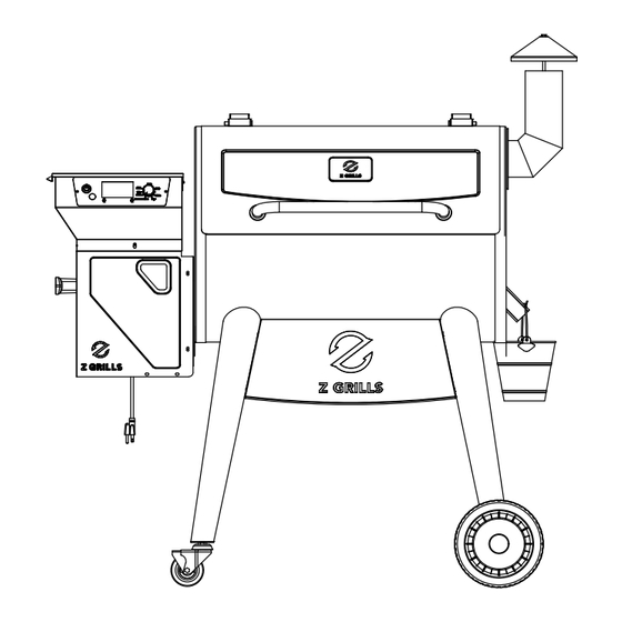
- Page 1 WOOD PELLET GRILLS ZPG-7002C3E OWNER’S MANUAL MON TO FRI, 8:00 A.M. - 5:00 P.M. PACIFIC STANDARD TIME SERVICE CONTACT: 1-833-947-4557/1-833-ZGRILLS EMAIL: support@zgrills.com WEBSITE: www.zgrills.com VN092023...
-
Page 3: Table Of Contents
CONTENTS IMPORTANT SAFETY INFO COMPONENT LIST ASSEMBLY INSTRUCTIONS INITIAL FIRING INSTRUCTIONS SUBSEQUENT START-UP OPERATING TIPS MAINTENANCE & CLEANING TROUBLESHOOTING DIGITAL THERMOSTAT CONTROL WIRING DIAGRAM Z GRILLS SUPPORT 3-Y LIMITED WARRANTY... - Page 4 SAVE THIS MANUAL FOR FUTURE REFERENCE...
-
Page 5: Important Safety Info
IMPORTANT SAFETY INFO GENERAL WARNINGS Please read this entire manual before installation and use of the pellet fuel-burning appliance. Failure to follow these instructions could result in property damage, bodily injury or even death. Contact local building or fire officials about restrictions and installation inspection requirements in your area. - Page 6 DO NOT place anything heavy on top of hopper lid. It is not a shelf and is a tip hazard. Never use gasoline, gasoline-type lantern fuel, kerosene, charcoal lighter fluid, or similar liquids to start or ‘freshen up’ a fire in this appliance. Keep all such liquids well away from the appliance when in use.
- Page 7 There is no guarantee that other brands of pellets are suitable for use in Z GRILLS. And Z GRILLS assumes no liability for any loss, damage or injury caused by the use of any other brands of pellets.
-
Page 8: Component List
COMPONENT LIST ITEM DESCRIPTION ITEM DESCRIPTION Chimney Cap Assembly Digital Control Smoke Stack Assembly Hopper Top Assembly Smoke Stack Gasket Hopper Burner Lid Grill Chamber Assembly RTD Temperature Probe Grease Bucket Lid Handle Right Rear Leg Lid Handle Guide Back Plate Side Plate Hinge Wheel Cap... - Page 9 HARDWARE PACKAGE LIST ITEM DESCRIPTION ITEM DESCRIPTION Bolt 1/4-20*5/8 Gasket OD0.94*ID0.51 Tapping Screw 1/3 Gasket OD0.79*ID0.26 Bolt 1/4-20*3/4 Bolt 8#-32*3/8 Spring Washer Hexagon Bolt 1/4-20*1/2 OD0.51*ID0.33 Bolt 1/4-20*2-3/8 Spring Washer OD0.39*ID0.26 Hexagon Nut 1/4-20 Open End Wrench Open End Wrench Hexagon Kep Nut 8#-32 Screwdriver Cap Nut 5/16-18...
-
Page 10: Assembly Instructions
ASSEMBLY INSTRUCTIONS PARTS DIAGRAM HOPPER BURNER ASSEMBLY... - Page 11 1.ASSEMBLING OF BOTTOM BASE 1. Take Left & Right Front Legs (13)(16) and use the Bolt (A) to assemble the Front Plate (10) through the holes, as shown. 2. Take Left & Right Rear Legs (6)(14) and use the Bolt (A) to assemble the Back Plate (7) through the holes, as shown.
- Page 12 3. Take Left & Right Legs (6)(13)(14)(16) and use the Bolt (A) to assemble the Side Plate (8) through the holes, as shown. Push the Axle (11) through the wheel (12), Gasket (J) and then through the hole in the legs as shown.
- Page 13 3. POSITIONING THE CHAMBER ON THE BODY FRAME Lift up the Chamber (4) on the Body Frame. Align the Chamber holes with the Frame holes and secure with Bolt (L), Spring Washer (N) and Gasket (I) in order, as shown. 4.ATTACHING THE CHAMBER LID HANDLE Use a wrench to remove the bolts that have been assembled in the lid handle.
- Page 14 5.ASSEMBLING OF HOPPER 1.Insert Hopper Top Assembly I (26) into Hopper Bottom Assembly (23), align the holes. 2. Secure the Digital Control (25) assembled on the Hopper Assembly with the Tapping Screw (B),as shown. 3. Secure the Control Wire Shield (22) assembled on the Digital Control with the Tapping Screw (B),as shown.
- Page 15 Usage of Pellet Cleanout Door Note: The Hopper is equipped on the back with a Pellet Cleanout Door to clear the hopper of unused pellets so as to replace with fresh pellets or pellets of a different smoking flavor. 1. Place a bucket or bowl below cleanout door to capture falling pellets. 2.
- Page 16 7.Installation instructions for RTD Temperature Probe 1.Remove the screws from the left plate of the grill chamber. 2.Use the screws through the RTD Temperature Probe and fix on the left plate of the grill chamber. 3.The distance between the RTD Temperature Probe and the left panel of the grill chamber should be kept about 14mm, otherwise the RTD Temperature Probe effect will be affected.
- Page 17 9.POSITIONING THE HEAT BAFFLE Position The Heat Baffle (17) on the locating brackets which is on the inside walls of the Grill. The notched legs should be facing downward. Slide Heat Baffle (17) to the right to lock in place. 10.POSITIONING THE GREASE DRAIN PAN Position The Grease Drain Pan (18) over the Heat Baffle (17) by fitting over the bracket on the left side of grill wall.
- Page 18 11.POSITIONING THE PORCELAIN GRILL Position the Porcelain Grills (19) inside the chamber. Install the Warming Rack (20) on the rack supports inside the chamber. 12.HANG ON THE GREASE BUCKET Locate the Grease Drain Tube which is on the right side of the chamber, then hang the Grease Bucket (5) on the hook.
-
Page 19: Initial Firing Instructions
Please read this manual carefully and follow it step by step before starting your Z Grills for the first time and each time the grill runs out of pellets. 1.Remove the Porcelain Grills, Warming Rack, Grease Drain Pan and Heat Baffle from the interior of the grill. -
Page 20: Subsequent Start-Up
Temperature Dial to any cooking setting desired. 5.If this step is not successful, see TROUBLESHOOTING or contact Z GRILLS Technical Support to help diagnose the problem. -
Page 21: Operating Tips
OPERATING TIPS 1.Like all grills, the actual temperature of this grill and the cooking times will be affected by external temperature, humidity, wind conditions, quality of pellets, etc. 2.It is beneficial to shelter your grill from the wind. This will aid in temperature output, heat retention and heat recovery time when the lid is open. -
Page 22: Maintenance & Cleaning
2.It is highly recommended that you use Z GRILLS Cover to protect your grill . 3.You can use a high-quality car wax on the outside surfaces of your grill to protect it’s finish. - Page 23 Clean the ash from the interior of the grill periodically. If excessive ash is in the firepot, it may cause the fire to go out. This is especially true in the SMOKE setting. A shop vac is an excellent tool to use for removing the ash. WARNING: MAKE SURE THE GRILL FIRE IS OUT, THE UNIT IS OFF, UNPLUGGED AND COLD BEFORE ATTEMPTING TO CLEAN ASH FROM THE GRILL.
-
Page 24: Troubleshooting
TROUBLESHOOTING CAUTION: Make sure the grill is completely cool and unplugged before you do any inspection, cleaning, maintenance or service work. Potential Problem Solution Cause Make sure the power cord is plugged Power in. Verify there is power at the electrical outlet. - Page 25 Pellets pellets. When contacting customer support Contact please have the following information Z GRILLS available: Your authorized Z Grills Customer dealer, your name, phone number, Get your new parts Service or your address, your Z Grill serial number and Z GRILLS part identification number.
-
Page 26: Digital Thermostat Control Wiring Diagram
DIGITAL THERMOSTAT CONTROL WIRING DIAGRAM Usage of the Meat Probe Put the plug of the Meat Probe into the control panel (PROBE1 or PROBE2) Insert the Probe into the food to measure the temperature The P1 temperature of the control panel is displayed as the temperature of PROBE1, while the P2 temp is displayed as the temp of PROBE2... -
Page 27: Z Grills Support
Thank you for purchasing a Z GRILL! If you have any question, please contact customer support or your Z GRILL dealer. Z GRILLS, INC. offers the best technical and sales support in the industry. When calling customer please be prepared to provide the following information: 1.Dealer's name and date of purchase... -
Page 28: 3-Y Limited Warranty
Z GRILLS, Inc. shall not be liable if you install, operate, clean or maintain your grill without following the owners' manual instructions. Misuse, abuse, alteration and natural disasters...
Need help?
Do you have a question about the ZPG-7002C3E and is the answer not in the manual?
Questions and answers