
Related Manuals for Denison Hydraulics PV Series


Summary of Contents for Denison Hydraulics PV Series
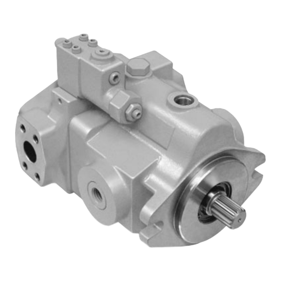
- Page 1 DENISON HYDRAULICS axial piston, variable displacement open loop pump series PV/PVT C-mod service information Publ. S1-AM009-F replaces S1-AM009 E...
-
Page 2: Table Of Contents
CONTENTS PAGE typical characteristics-------------------------------------------------------------------------------------- 3 fluid connections------------------------------------------------------------------------------------------- 3 higher speed guides---------------------------------------------------------------------------------------- 4 general information---------------------------------------------------------------------------------------- 4 operation of pump----------------------------------------------------------------------------------------- 5 mounting----------------------------------------------------------------------------------------------------- 5 shaft options------------------------------------------------------------------------------------------------- 5 shaft information------------------------------------------------------------------------------------------- 5 side load capability----------------------------------------------------------------------------------------- 5 piping-------------------------------------------------------------------------------------------------------- 5 system relief valves---------------------------------------------------------------------------------------- 5 service information----------------------------------------------------------------------------------------- 6 recommended fluids--------------------------------------------------------------------------------------- 6 viscosity----------------------------------------------------------------------------------------------------- 6 viscosity index---------------------------------------------------------------------------------------------- 6... -
Page 3: Typical Characteristics
DATA TYPICAL CHARACTERISTICS Specification Term Series Series Series Series Series PV10 PV15 PV20 PV29 PVT6 PVT10 PVT15 PVT20 PVT29 •displacement /rev. 0.88 1.26 2.09 2.62 3.78 at max angle /rev. 14.4 21.1 34.2 42.9 61.9 •pressure, continuous 3500 3500 3500 3500 3000 intermittent... -
Page 4: Higher Speed Guides
DATA HIGHER SPEED GUIDES Minimum inlet pressure maximum speed pressure gage absolute pressure case pressure in-Hg mm-Hg 1800 -3.00 -0.21 -6.12 -155 11.70 0.80 0.69 2050 -3.00 -0.21 -6.12 -155 11.70 0.80 0.48 2100 -3.00 -0.21 -6.12 -155 11.70 0.80 0.34 PVT6 2750... -
Page 5: Operation Of Pump
0.075-1.0 mm at 45° to clear radii that exist in the keyway. SIDE LOAD CAPABILITY: The PV series is designed for inline-drive and side loading on the shaft is not recom- mended. If this is unavoidable consult your nearest DENISON HYDRAULICS repre- sentative. -
Page 6: Service Information
The fluid recommended for use in these pumps has a petroleum base and contains agents which provide oxidation inhibition and anti-rust, anti-foam and de-aerating prop- erties as described in DENISON HYDRAULICS standard HF-1. Where anti-wear addi- tive fluids are specified, see DENISON HYDRAULICS standard HF-0. -
Page 7: Troubleshooting
TROUBLESHOOTING STARTUP PROCEDURE pressure readings can be made at appropriate places. • If solenoids in system, check for actuation. (continued) • Start pump drive. Make sure pump fills properly. • Bleed system of air. Recheck fluid level. • Cycle unloaded machine at low pressure and observe actuation (at low speed, if possible). - Page 8 TROUBLESHOOTING TROUBLESHOOTING effect of trouble possible cause fault which needs remedy pressure shocks cogging load mechanical considerations (continued) worn relief valve needed repairs worn compensa- needed repairs slow response in replace or relocate check valves excessive de- improve decompression control compression energy rates excessive line...
-
Page 9: Assembly Tool Drawings
ASSEMBLY TOOL DRAWINGS .039 R. (1mm) DIA. FIGURE 1 SHAFT SEAL INSTALLATION TOOL SERIES C† D&E PV6 & 1.75 2.17 .185 .078 R. PVT6 mm 44.5 55.1 (2 mm) .039 R. PV10 & in. 1.75 2.17 .185 (1 mm) PVT10 mm 44.5 55.1 PV15 &... - Page 10 ASSEMBLY TOOL DRAWINGS FIGURE 4 TRUNNION ASSEMBLY TOOL SERIES B† REF. PV6 & 1.75 .997/.996 1/2-13 x 3/4 dp. 039-91348 PVT6 mm 44.45 25.32/25.30 PV10 & in. 1.75 .997/.996 1/2-13 x 3/4 dp. 039-91348 PVT10 mm 44.45 25.32/25.30 PV15 & in. 2.00 1.247/1.246 3/4-10 x 1.00 dp.
-
Page 11: Disassembly Procedure
UNIT DISASSEMBLY DISASSEMBLY PROCEDURE Disassemble the pump according to the instructions in this section. Please refer to the explod- ed view (Fig. 6). Pump disassembly for inspection should be limited to the following cases: a) Malfunction or oil leakage resulting from damage or wear and tear. b) Trouble-shooting procedures described herein do not solve the problem. -
Page 12: Trunnion Removal
UNIT DISASSEMBLY DISASSEMBLY PROCEDURE bearing 36. Guide sleeve must be placed upward. Cover the block with a dust-proof plastic film. continued c) Place PC valve 28 with the machined face that attaches to port block 2 upward. Cover the PC valve with dust-proof plastic film. If unit contains a torque limiter, place torque limiter in a plastic bag. -
Page 13: Rework Limits Of Wear Parts
UNIT DISASSEMBLY COMPENSATOR DISASSEMBLY 23. Loosen hex. nut 28-12 and remove adjusting screw 28-11 from cap 28-3. 24. Remove cap 28-3. 25. Remove spring 28-6 and spring seat 28-5. 26. Remove spool 28-2. ‘F’ AND ‘L’ COMPENSATOR 27. If control is F or L compensator, loosen hex. nut 28-12 and remove adjusting screw 28-18 from body 28-1 . -
Page 14: Parts Inspection
PARTS INSPECTION part inspection procedure corrective action housing Check for cracks around tapped holes. Replace if cracked. Check for cracks around retainer ring groove. Replace if cracked Perform dye color check over entire housing when oil leakage Replace if cracked. is observed port block Defect can be observed. - Page 15 PARTS INSPECTION part inspection procedure corrective action piston assembly seizure, scoring or discoloring. Replace both piston ass’y. 5 and cylinder barrel 3. Check hydraulic fluid type, temperature rise, exces- sive pressure and correct as required. drive shaft Visual check of shaft end’s outer surface. Remove with emery paper.
- Page 16 PARTS INSPECTION part inspection procedure corrective action spring (continued) PV-20 1.97 in., or 50 mm Replace when height is decreased PV-29 2.05 in,. or 52 mm more than 5% from the given heights. spring Measure free heights. PV-6 2.44 in., or 62 mm Replace when height is decreased PV-10 2.60 in., or 66 mm more than 3% from the given...
- Page 17 ITEM 28 (‘J’ OR ‘K’ TORQUE LIMITER) FIGURE 6 PV/PVT EXPLODED VIEW...
-
Page 18: Parts List
PARTS LIST item description PV6/PVT6 PV10/PVT10 PV15/PVT15 PV20/PVT20 PV29/PVT29 housing, UNF 039-91366 039-91367 039-91368 039-91369 039-91370 housing, BSPP 039-91371 039-91372 039-91373 039-91374 039-91375 housing, UNF for ‘J’ or ‘K’ torque limiter 039-92157 039-92158 039-92159 039-92160 039-92161 housing, BSPP for ‘J’ or ‘K’ torque limiter 039-92177 039-92178 039-92179... -
Page 19: Seal Kit
PARTS LIST item description PV6/PVT6 PV10/PVT10 PV15/PVT15 PV20/PVT20 PV29/PVT29 PVT rear adapter kit, SAE-A S29-15433 S29-15430 S29-15430 S29-15430 S29-15430 PVT rear adapter kit, SAE-B N.A. S29-15431 S29-15431 S29-15431 S29-15431 PVT rear adapter kit, SAE-C N.A. N.A. N.A. S29-15432 S29-15432 69-1 rear mount adapter, PVT6/SAE 82-2 (SAE-A) 039-91974 rear mount adapter, PVT/SAE 101-2 (SAE-B) - Page 20 PARTS LIST ITEM 28, ‘J’ AND ‘K’ TORQUE LIMITER VALVE (USE WITH ‘F’ OR ‘L’ COMPENSATOR VALVE) item description PV6/PVT6 PV10/PVT10 PV15/PVT15 PV20/PVT20 PV29/PVT29 assembly no. ‘J’ torque limiter S29-15581 S29-15581 S29-15580 S29-15579 S29-15579 assembly no. ‘K’ torque limiter S29-15526 S29-15525 S29-15524 S29-15523...
-
Page 21: Assembly Procedure
ASSEMBLY PROCEDURE CLEANING AND INSPECTION The assembly operation must be performed more carefully than the disassembly oper- ation and should be performed in a clean environment using parts that have been ade- quately cleaned. Check the disassembled parts with the exploded view given in Fig. 6 for any missing parts or irregularities. -
Page 22: Barrel, Piston/Shoe/Retainer
ASSEMBLY PROCEDURE Place cylinder barrel 3 on a clean sheet of paper or cloth and insert the three dowels 56 into the holes located outside of the spline hole. Place the holddown ball 14 on top. Compress manually and ascertain spring 18 force. BARREL, Hold the shoe retainer 15 horizontally with one hand, insert the 9 piston assemblies 5 into the bores of the shoe retainer, in order of disassembly. -
Page 23: Torque On Housing Bolts
ASSEMBLY PROCEDURE TORQUE ON HOUSING BOLTS The final tightening torque should be as follows: lb.-ft series min. max. min. PV/PVT6 12.0 15.0 16.3 20.3 PV/PVT10 35.8 40.0 48.5 54.2 PV/PVT15 60.0 65.0 81.3 88.0 PV/PVT20 70.1 82.7 95.0 112.0 PV/PVT29 113.2 132.1 152.9... -
Page 24: J' & 'K' Torque Limiter
ASSEMBLY PROCEDURE Carefully clean the valve body 28-1 and spool 28-2 and soak in clean hydraulic fluid. Check O-Rings 28-8 and 28-9 for deformation and wear (as given in no. 28 of "INSPECTION") and when determined to be in good condition, assemble 28-8 to cap, 28-3, and 28-9 to spring seat 28-4. -
Page 25: T' Power Limiter
ASSEMBLY PROCEDURE T’ POWER LIMITER ‘T’ power limiter valve 28 is assembled as follows: See figure 11. Carefully clean the valve body 28-1 and spool 28-2 and soak in clean hydraulic fluid. Install orifice 28-30 in body as shown. To install seat 28-15, insert open end into bore and press in place, beyond the thread- ed hole for fitting, 28-27. -
Page 26: Final Assembly
ASSEMBLY PROCEDURE FINAL ASSEMBLY Assemble compensator or power limiter valve 28 on the mounting pad of port block. The tightening torque is as follows: 8.3 to 9.7 Ibs.-ft., 11 .3 to 13.2 Nm. If the pump contains the ‘J’ or ‘K’ torque limiter, place the control on its mounting pad with the feedback arm on the barrel side of the hanger, with the adjustment facing the same way. -
Page 27: Pump Test
TEST PROCEDURE 1770 ±. 30 RPM TEST CONDITIONS Operating speed: ± 10 ± 5.5 Oil temperature F., 49 Case pressure 3 to 10 PSI, .21 to .69 bar With the operating speed at 1770 ±30 RPM, record delivery flow rate, drain flow rate PUMP TEST and fluid temperature at minimum outlet pressure and maximum rated continuous pressure. -
Page 28: J' & 'K' Torque Limiter Test
TEST PROCEDURE ‘J’ AND ‘K’ TORQUE LIMITER 1. Note: on all pump adjustment screws, CW rotation increases the setting, and CCW decreases the setting. 2. On the “F” (or “L”) control, back out the maximum pressure adjustment until there is no resistance, and set the differential spool to 250 psi, 17,2 bar. -
Page 29: T' Power Limiter Test
TEST PROCEDURE ‘T’ POWER LIMITER TEST Power limiter setting consists of first adjusting the flow (1) at the high pressure com- pensator setting for the required horsepower, then adjusting the high flow pressure adjustment (3) to the required horsepower at full volume. Before plumbing the pres- sure line to the pump, check for the presence of the orifice 28-28 in the pressure port. -
Page 30: Compensator Section Drawings
COMPENSATOR SECTION DRAWINGS PRESSURE COMPENSATOR ADJUSTMENT SCREW "C" COMPENSATOR "V" VENT PORT PRESSURE COMPENSATOR ADJUSTMENT SCREW 250-400 PSI DIFFERENTIAL PRESSURE ADJUSTING SCREW (17-28 BAR) "F" COMPENSATOR "V" VENT PORT PRESSURE COMPENSATOR ADJUSTMENT SCREW 250-400 PSI DIFFERENTIAL PRESSURE ADJUSTING SCREW "L" COMPENSATOR (17-28 BAR) -
Page 31: Pv6 Installation
"V" COMPENSATOR VENT PORT SAE - 4 7/16-20 UNF-2B (BSPP-1/4" THREADS - OPTIONAL) 1.54 FOR CW FOR CCW 1.79 4.11 (39,1) (45,5) (104,4) .1884 4.56 .1874 (115,8) SQUARE KEY (4,785) 1.46 3.78 (4,760) (37,1) (96,0) 2.79 (70,9) 1.00 (25,4) .832 (21,13) 6.71 (170,4) -
Page 32: Pv10 Installation
COMPENSATOR VENT PORT "V" SAE - 4 7/16-20 UNF-2B 1.61 2.33 4.31 (BSPP-1/4" THREADS - OPTIONAL) FOR CCW FOR CW (59,2) (40,9) (109,5) 1.88 (47,8) 1.25 (31,8) .2510 4.84 .2500 SQUARE KEY (122,9) (6,375) (6,350) 4.06 (103,1) 3.07 (78,0) .987 (25,07) 7.20 (182,9) -
Page 33: Pv15 Installation
COMPENSATOR VENT PORT "V" SAE - 4 7/16-20 UNF-2B (BSPP-1/4" THREADS - OPTIONAL) 2.29 1.89 5.00 FOR CCW FOR CW (48,0) (58,2) (127,0) 1.88 (47,8) 1.25 .2510 .2500 (31,8) SQUARE KEY 5.23 4.45 (6,375) (113,0) (132,8) (6,350) 3.46 (87,9) 7.95 (201,9) .987 (25,07) -
Page 34: Pv20 Installation
COMPENSATOR VENT PORT "V" SAE - 4 7/16-20 UNF-2B (BSPP-1/4" THREADS - OPTIONAL) 1.93 11.47 (49,0) (291,3) 2.30 5.53 (58,4) (140,5) FOR CW FOR CCW 1.87 (47,5) 1.25 .3136 (31,8) .3126 SQUARE KEY 5.43 (7,965) 4.65 (137,9) (7,940) (118,1) 3.66 (93,0) 1.391 (35,33) -
Page 35: Pv29 Installation
COMPENSATOR VENT PORT "V" SAE - 4 7/16-20 UNF-2B (BSPP-1/4" THREADS - OPTIONAL) 12.05 (306,1) FOR CCW FOR CW 2.36 2.32 6.18 (59,9) (58,9) (157,0) 5.90 5.12 .3136 (149,9) .3126 (130,0) SQUARE KEY 4.13 (7,965) 1.87 (104,9) (7,940) (47,5) 1.25 (31,8) 9.24 (234,7) -
Page 36: Pvt6 Installation
COMPENSATOR VENT PORT SAE - 4 7/16-20 UNF-2B (BSPP-1/4" THREADS - OPTIONAL) 10.01 MAXIMUM (254,3) 9.41 1.54 (239,0) FOR CCW FOR CW (39,1) 1.79 4.11 (45,5) (104,4) 1.46 (37,1) 1.00 .1884 4.56 .1874 (25,4) SQUARE KEY (115,8) (4,785) 3.78 (4,760) (96,0) 2.79 (70,9) -
Page 37: Pvt10 Installation
COMPENSATOR VENT PORT 11.58 SAE - 4 7/16-20 UNF-2B MAXIMUM 1.61 (294.1) (BSPP-1/4" THREADS - OPTIONAL) 10.21 FOR CW (40,9) (259,3) FOR CCW 2.33 4.31 (59,2) (109,5) 1.88 .2510 .2500 (47,8) SQUARE KEY (6,375) 1.25 4.84 (6,350) (31,8) (122,9) 1.25 DIA. (REF.) 4.06 (103,1) -
Page 38: Pvt15 Installation
12.41 COMPENSATOR VENT PORT MAXIMUM SAE-4 7/16-20 UNF-2B (315.2) 10.85 (BSPP-1/4" THREADS - OPTIONAL) 1.89 (275,6) FOR CCW FOR CW (48,0) 2.29 5.00 (58,2) (127,0) SAE 22-1 (SAE B) 1.88 .2510 (47,8) .2500 SQUARE KEY 1.25 (6,375) (31,8) (6,350) 4.45 5.23 1.50 DIA. -
Page 39: Pvt20 Installation
13.32 MAXIMUM (338,3) COMPENSATOR VENT PORT 11.47 1.93 SAE - 4 7/16-20 UNF-2B (49,0) (291,3) (BSPP-1/4" THREADS - OPTIONAL) 2.30 5.53 (58,4) (140,5) FOR CW FOR CCW 1.87 (47,5) 1.25 (31,8) SAE 32-1 (SAE C) 5.43 4.65 (137,9) .3136 (118,1) 1.50 DIA. -
Page 40: Pvt29 Installation
COMPENSATOR VENT PORT MAXIMUM 14.14 SAE - 4 7/16-20 UNF-2B (359,2) 12.05 (BSPP-1/4" THREADS - OPTIONAL) (306,1) 2.36 FOR CCW FOR CW 2.32 6.18 (59,9) (58,9) (157,0) 1.87 (47,5) 2.00 DIA. 5.90 .3136 (REF.) 1.25 5.12 (149,9) .3126 (31,8) (130,0) 4.13 SQUARE KEY (7,965) -
Page 41: J' & 'K' Torque Limiter Installation
COMPENSATOR VENT CONNECTION COMPENSATOR OVERRIDE ADJUSTMENT 7/16-20 JIC 37° (MAXIMUM PRESSURE) 1.50 TYP. DIFFERENTIAL SPOOL ADJUSTMENT "A" CCW ROTATION: TUBE AND "F" COMPENSATOR ON THIS SIDE TORQUE LIMIT 1.88 CW ROTATION: ADJUSTMENT TYP. TUBE AND "F" COMPENSATOR ON THIS SIDE "J"... -
Page 43: Ordering Code
ORDERING CODE C -C 0 -A Pump series PV -variable volume pump - no rear drive PVT -variable volume pump - side ported or rear drive Flow at 1800 rpm 6 -6.8 gpm, 25,7 Lpm 10 -10.0 gpm, 37,9 Lpm 15 -16.3 gpm, 61,7 Lpm 20 -20.4 gpm, 77,2 Lpm 29 -29.5 gpm, 111,7 Lpm... -
Page 44: Conversions & Formulas
CONVERSIONS & FORMULAS DEFINITION & UNIT /rev x 16.387 = cm /rev /rev x 0.06102 = in /rev displacement U.S.gpm x 3.78 = L/min L/min x 0.264 =U.S. gpm flow hp x 0.7457 = kW kW x 1.341 = hp power torque lb-ft x 1.3558 = Nm... -
Page 45: Notes
NOTES... - Page 46 NOTES...
- Page 47 NOTES...
- Page 48 SALES & SERVICE WORLDWIDE International Distributors Australia France Mexico, Central America, South In Europe: DENISON HYDRAULICS Pty. Ltd. DENISON HYDRAULICS America and Caribbean Cyprus 41-43 St. Hillers Road FRANCE SA Countries Contact Eastern Europe P.O. Box 192 14, route du Bois Blanc DENISON HYDRAULICS Inc.
Need help?
Do you have a question about the PV Series and is the answer not in the manual?
Questions and answers