
Related Manuals for Denison Hydraulics P11S Series


Summary of Contents for Denison Hydraulics P11S Series
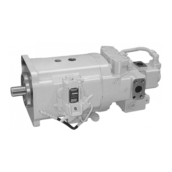
- Page 1 DENISON HYDRAULICS axial piston variable displacement with auxiliary package external replenishing pump Goldcup series P11S & P14S C mod service information Publ. S1-AM023-C Revised 6/04 www.comoso.com...
-
Page 2: Table Of Contents
CONTENTS PAGE seal kits - - - - - - - - - - - - - - - - - - - - - - - - - - - - - - - - - - - - - - - - - - - - - - - - - - - - -2 typical characteristics - - - - - - - - - - - - - - - - - - - - - - - - - - - - - - - - - - - - - - - - - - - -3 fluid connections - - - - - - - - - - - - - - - - - - - - - - - - - - - - - - - - - - - - - - - - - - - - - - -3 installation - - - - - - - - - - - - - - - - - - - - - - - - - - - - - - - - - - - - - - - - - - - - - - - - - - -4... -
Page 3: Typical Characteristics
INSTALLATION TYPICAL CHARACTERISTICS Specification Term Goldcup 11 Goldcup 14 • displacement at max. angle /rev. 11.00 14.00 /rev. (180) (229) • pressure continuous 5000 5000 (345) (345) • pressure intermittent 6000 6000 (414) (414) • speed, max. continuous-full stroke 2400 2400 •... -
Page 4: Installation
INSTALLATION INTRODUCTION The DENISON HYDRAULICS Goldcup 11 and Goldcup 14 axial piston pumps feature advance design concepts which are time proven and provide for advance pumping and control concepts. The instructions contained in this manual cover complete disassem- bly and re-assembly of the unit. Before proceeding with the disassembly or re-assem- bly of any unit, this manual should be studied in order to become familiar with proper order and parts nomenclature. -
Page 5: Maintenance
Water glycol solutions HF-4 Phosphate esters HF-5 Consult DENISON HYDRAULICS for design requirements and warranty limitations for service with this class of fluids. See DENISON HYDRAULICS bulletin SPO-AM305 for more information. MAINTENANCE This pump is self-lubricating and preventative maintenance is limited to keeping sys- tem fluid clean by changing filters frequently. -
Page 6: Troubleshooting
TROUBLESHOOTING START UP PROCEDURES FOR • Bleed system of air. Recheck fluid level. • Cycle unloaded machine at low pressure and observe actuation (at low speed, if NEW INSTALLATION possible). (continued) • Increase pressure settings gradually in steps. Check for leaks in all lines especially in pump and motor inlet lines. - Page 7 TROUBLESHOOTING effect of trouble possible cause fault which needs remedy pressure shocks cogging load mechanical considerations worn relief valve needed repairs worn compensa- needed repairs slow response in replace or relocate check valves servo pressure increase pressure and check pressure drop too low to through servo filter maintain firm...
-
Page 8: Disassembly
UNIT DISASSEMBLY INTRODUCTION The instructions contained in this section cover a complete teardown of the subject pump. Disassemble only as far as necessary to replace or repair any worn parts. DISASSEMBLY Position pump unit so that valve block assembly is on top. A bench or similar suitable surface capable of supporting unit should be used. -
Page 9: Rework Of Wear Part
UNIT DISASSEMBLY DRIVE SHAFT See figure 16. Remove bearing pre-load spring (27). Remove the four screws (8) and gaskets (7). Remove seal retainer (6), and shaft assembly (1) from pump. Note: Version “A” pumps contain a mechanical shaft seal. Replacement kits S23-15218 (CW rotation) or S23-15349 (CCW rotation) contain all the parts to modify earlier models to the version C design. -
Page 10: Assembly
ASSEMBLY PROCEDURES CLEANING AND INSPECTION All parts must be inspected and be free of material defects, dirt, scratches or any for- eign material. All parts must be cleaned with a suitable cleaning solvent and all holes and passages blown out with dry, clean, compressed air. After cleaning and inspection, all parts must be covered with a light film of oil and protected from dirt and moisture. - Page 11 ASSEMBLY PROCEDURES PARTS LIST FOR FIGURE 3 item description part no. qty. rocker cam, pistons and retainer retaining ring (yellow) .107”-.109” (2.72-2.77mm) 033-71556 retaining ring (green) .105”-.107” (2.67-2.72 mm) 033-71557 retaining ring (red) .103”-.105” (2.62-2.67 mm) 033-71558 retaining ring (blue) . 101”-.103” (2.56-02.62 mm) 033-71559 retaining ring (white) .098”-.100”...
-
Page 12: Rocker Cam Assembly
ASSEMBLY PROCEDURES FIGURE 3 rocker cam assembly ROCKER CAM ASSEMBLY See figure 3. Position the cradle (19) on a clean flat surface with the large flat area down. Position the rocker cam (22) on the cradle (19). Note marks made earlier to indicate top of rocker cam &... -
Page 13: Piston/Shoe/Retainer Assembly
ASSEMBLY PROCEDURES place with a plastic mallet. Install two orifice screws (7) in the servo stem (6). Position the stem on the rocker cam input side at 9 o’clock position on “B” suffix, or 3 o’clock for “A” suffix models. Install servo stem on rocker cam using screws (8). -
Page 14: Housing Assembly
ASSEMBLY PROCEDURES HOUSING ASSEMBLY See figure 5: Wash and dry all parts. During assembly, lapped and ground surfaces should be kept lubricated with clean oil and protected from nicks or surface damage. NOTCH Position housing (1) on a clean flat surface with the large open end up. Clean housing (1) and barrel bearing (2). -
Page 15: Port Block Assembly
ASSEMBLY PROCEDURES PORT BLOCK ASSEMBLY See Figure 7: Position the port block (1) on a clean flat surface with the two open ports up. THE OPPOSITE FACE MUST NOT BE SCRATCHED OR DAMAGED. Position needle bearing (2) on tool (figure T-1) with the marked end of the bearing against the shoulder on the tool and press the bearing (2) into the port block. -
Page 16: Gerotor & Barrel Holddown
ASSEMBLY PROCEDURES PARTS LIST FOR FIGURE 8 item description part no. qty. port block/housing assembly hex head cap screw 306-40172 port block assembly (figure 7) S13-44138 port plate pins 324-21610 RH port plate 11 in3 033-71915 LH port plate 11 in3 033-71914 RH port plate 14 in3 033-71617... - Page 17 ASSEMBLY PROCEDURES PARTS LIST FOR FIGURE 9 item description part no. qty. side plate 033-71619 gerotor and barrel holddown square key 1/8 x 9/16 211-22034 gerotor and eccentric ring assy, replenishing. S13-43334 center port plate S13-43963 square key 1/8 x 9/16 211-22034 gerotor and eccentric ring assy, servo.
-
Page 18: Valve Block Assembly(After 7-93)
ASSEMBLY PROCEDURES FIGURE 10 valve block assembly(after 7-93) VALVE BLOCK ASSEMBLY (after 7-93) Note: Do not use impact tools or over-tighten threaded parts. Wash and dry all parts. During assembly, lapped and ground surfaces should be kept lubricated with clean oil and protected from nicks or surface damage. See figure 10: Place valve block (1) with the six poppet valve bores up in order to press two spring pins (26) in position. - Page 19 ASSEMBLY PROCEDURES Place springs (35), 1.09” (27.7 mm) into bores next to the sequence poppet valves. Place dual relief poppet (31) over these springs. Position seats (28) with the groove side facing up, over poppets. Place spring (32) 1.56” (39.6 mm) long, into bore next to compensator valve side of block.
-
Page 20: Valve Block Assembly For Special Mounting Of Servovalve (After 7-93)
ASSEMBLY PROCEDURES FIGURE 11 valve block assembly for special mounting of servovalve (after 7-93) VALVE BLOCK ASSEMBLY Note: Do not use impact tools or over tighten threaded parts. FOR SPECIAL MOUNTING OF SERVOVALVE See figure 11: Wash and dry all parts. During assembly, lapped and ground surfaces (after 7-93) should be kept lubricated with clean oil and protected from nicks or surface damage. - Page 21 ASSEMBLY PROCEDURES Place springs (33), 1.43” (36.3 mm) into outermost bores at each end of the valve block. Place sequence poppets (30) over these springs. Position seats (27) small shoulder side first over poppets. Place springs (35), 1.09” (27.7 mm) into bores next to the sequence poppet valves. Place dual relief poppet (31) over these springs.
- Page 22 ASSEMBLY PROCEDURES PARTS LIST FOR FIGURE 11 item description part no. qty. valve block 033-91335 valve block assembly for special check valve assembly S13-40266 mounting of servovalve orifice plug .047” (1.2 mm) 033-91249 (after 7-93) O-ring 90 S-1 ARP 903 691-00903 seat 033-70508...
-
Page 23: Adapter Assembly
ASSEMBLY PROCEDURES FIGURE 12 adapter assembly ADAPTER ASSEMBLY See figure 12: Place wave spring, (8) over isolation tube (4). Lube O-ring (7) and assemble to isolation tube. Place isolation tube against pressure plate. Lube O-ring (5) and assemble to adapter (1). Lube tetraseals (10). -
Page 24: Pilot Valve Assembly
ASSEMBLY PROCEDURES FIGURE 14 shuttle valve SHUTTLE VALVE ASSEMBLY See figure 14: Lube spool (3) and insert it into valve body (1). When the spool is full- S23-11966 (external drain) ly engaged, move the spool back and forth a few times to check for smooth operation. Spool must move freely in body bore. - Page 25 ASSEMBLY PROCEDURES PARTS LIST FOR FIGURE 15 item description part no. qty. orifice 036-25528 pilot valve assembly O-ring, 90 S-5 ARP 013 695-00013 S23-12007 (external drain) 036-38910 setscrew 312-35051 spacer 036-27548 piston 036-11694 block 036-11710 seat 036-11692 cone 036-12288 spring 036-32465 spring 036-85514...
-
Page 26: Shaft & Seal Installation
ASSEMBLY PROCEDURES INPUT CONTROLS DESCRIPTION part no. 1O* screw adjustment CW “B” mtg, CCW “A” mtg. S23-12327 CW “A” mtg, CCW “B” mtg. S23-12328 2H (three position cylinder control) S23-12358 4O* (spring centered rotary servo) S23-12344 4A* (spring centered rotary servo with adjustable stops) S23-12325 4B* (spring centered rotary servo with automatic brake valve) S23-12343... -
Page 27: A Mod Shaft Seal Replacement
ASSEMBLY PROCEDURES Tool T-3 Tool T-4 C - MOD SHAFT SEAL INSTALLATION TOOLS shaft A diameter item material splined 1.723/1.722 (43.76/43.74 mm) ABS cap for 2” sch. 40 pipe keyed 1.752/1.751 (44.50/44.48 mm ABS 2” sch. 40 pipe ABS coupling for 2” sch. 40 pipe Note: Seal installation must be completed quickly to avoid the rubber friction ring seiz- A - MOD SHAFT SEAL ing on the shaft. -
Page 28: Control Cover Installation
80 - 120 in.-lb. (9.04 - 13.56 Nm) torque. The adapter block must be removed to install the isolation plug. CAUTION: the filter must have bypass and bypass indicator. Denison Hydraulics rec- ommends it be sized to four times the expected flow. -
Page 29: Gage Pressure Ranges
CONVERSION OF DESIGN A OR DESIGN B TO DESIGN C GAGE PRESSURE RANGES AG, BG & V: 6000 PSI (68.9 bar) gage for A or B port DG: 200 PSI (13.7 bar) gage for case port KG: 500 PSI (35 bar) gage for replenishment port G, G2: 1000 PSI (68.9 bar) gage for servo port. -
Page 30: Test Procedure
TEST PROCEDURE GENERAL REQUIREMENTS 1. Maximum runout between pump shaft and electric motor shaft .003 T.I.R. (.076 mm). 2. Electric motor speed - 1800 RPM. 3. Inlet temperature - 130 ± 10 F. (54 ± 4 4. Inlet condition Main pump 100 to 150 PSI. - Page 31 TEST PROCEDURE Note: There is no servo relief valve adjustment. Increasing or decreasing repl. pres- sure will cause both servo and repl. pressure to change by the same amount. 9. Set pump to compensate at 5000 PSI (345 bar). Record repl. and servo pressure. Servo pressure-minus case pressure 660 to 770 PSI (45.5 to 53.1 bar) Repl.
-
Page 32: Installation Drawing
INSTALLATION DRAWING www.comoso.com... - Page 33 INSTALLATION DRAWING www.comoso.com...
-
Page 34: Hydraulic Circuit
HYDRAULIC CIRCUIT www.comoso.com... - Page 35 HYDRAULIC CIRCUIT www.comoso.com...
-
Page 36: Pump Key Sheet
PUMP KEY SHEET P 11 S - 2R1C - 4A2 - A - 00 - 0B1 - M2 - XXXXX Designates special Pump Series External mounting Displacements, max. 0 - pump not mounted 11 - ll.0 in /rev., 98 cc/rev. 1 - pump mounted 14 - 14.0 in /rev., 119 cc/rev. -
Page 37: Conversion Formulas
CONVERSIONS AND FORMULAS DEFINITION & UNIT /rev x 16.387 = cm /rev /rev x 0.06102 = in /rev displacement gpm x 3.78 = L/min L/min x 0.2642 = gpm flow hp x 0.7457 = kW kW x 1.341 = hp power torque lb-ft x 1.3567 = Nm... - Page 38 NOTES www.comoso.com...
- Page 39 NOTES www.comoso.com...
- Page 40 Contact your local distributor or call toll-free for the distributor nearest you at 800-551-5956 http://www.denisonhydraulics.com Printed in USA HP 06-01 www.comoso.com...
Need help?
Do you have a question about the P11S Series and is the answer not in the manual?
Questions and answers