Denison Hydraulics Premier Series Service Information
Open loop pump control
Hide thumbs
Also See for Premier Series:
- Service information (80 pages) ,
- Service information (48 pages) ,
- Service information (80 pages)

Related Manuals for Denison Hydraulics Premier Series


Summary of Contents for Denison Hydraulics Premier Series
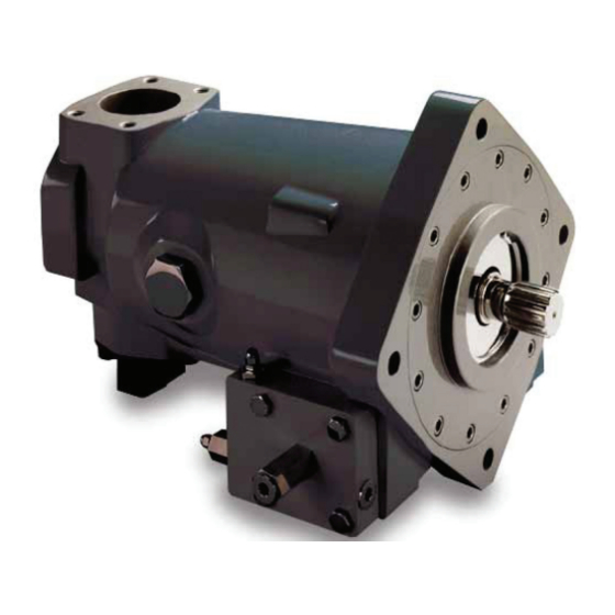
- Page 1 DENISON HYDRAULICS Premier Series open loop pump controls series P080 service information Publ. S1-AM027 Internet: http://www.denisonhydraulics.com E-mail: denison@ denisonhydraulics.com www.comoso.com...
-
Page 2: Table Of Contents
CONTENTS PAGE typical characteristics------------------------------------------------------------------------------- fluid connections------------------------------------------------------------------------------------- introduction------------------------------------------------------------------------------------------ general--------------------------------------------------------------------------------------------- description----------------------------------------------------------------------------------------- pressure compensator---------------------------------------------------------------------------- remote compensator control--------------------------------------------------------------------- load sensing control------------------------------------------------------------------------------ torque limiter-------------------------------------------------------------------------------------- rotary servo control------------------------------------------------------------------------------- hydraulic stroker---------------------------------------------------------------------------------- electric stroker------------------------------------------------------------------------------------- pressure compensator override and torque limiter override-------------------------------- troubleshooting chart------------------------------------------------------------------------------- pressure compensator parts list------------------------------------------------------------------- figure 1 & parts list, maximum volume stop-------------------------------------------------- figure 2 &... -
Page 3: Typical Characteristics
• electric stroker control amps (12V) 0 disp. full disp. pulse width modulation frequency: 100-150 Denison Hydraulics electric stroker accessories mating connector: Din 43650 type AF part no. 167-10008-8 (provided) Jupiter driver S20-14078 Jupiter power supply S20-11715 Options card S20-ll716 Venus controller 020-14103 •... -
Page 4: Introduction
INTRODUCTION GENERAL The instructions contained in this manual cover complete disassembly and reassembly of the con- trols. Before proceeding with the disassembly or reassembly of any unit, this manual should be studied in order to become familiar with proper order and parts nomenclature. DESCRIPTION OF OPERATION A piloted three-way valve spool and sleeve combination is the nucleus of the control function. -
Page 5: Electric Stroker
INTRODUCTION ELECTRIC STROKER By mounting an electrically modulated pressure control valve on the hydraulic stroker to establish the control pressure, pump stroke is controlled by an electrical signal. At approximately 125 mA electrical signal, the pump commences to stroke, and at approximately 290 mA, the pump will be at full stroke. -
Page 6: Pressure Compensator Parts List
PRESSURE COMPENSATOR CCW ROTATION CW ROTATION ITEMS NOT SHOWN P080 QTY. PRESSURE COMPENSATOR ITEM DESCRIPTION PART NO. Max. Vol. Stop (Fig. 1) S22-15467 — parts list Max Vol. Handwheel (Fig. 2) S22-15448 — Compensator Control (Fig. 3) S22-15623 — Compensator Control S22-15633 —... - Page 7 PRESSURE COMPENSATOR PARTS LIST FOR FIGURE 1, MAX. VOL. STOP S22-15467 ITEM DESCRIPTION PART NO. QTY. Plug 8HP5N-S 488-35018 O-Ring, 90 S-1 ARP 908 691-00908 Nut, M16 Hex 032-91822 Screw, Soc. Set 311-50001 O-Ring,70 S -1 ARP 115 671- 00115 FIGURE 1 MAXIMUM VOLUME STOP MAXIMUM VOLUME HANDWHEEL...
-
Page 8: Compensator Disassembly, Assembly, Test
PRESSURE COMPENSATOR COMPENSATOR DISASSEMBLY 1. See Figure 3. Back off max. volume screw or handwheel to full displacement. Remove max. volume screw or handwheel assembly. 2. Remove bolts holding cap to pump. 3. Remove plug (15) and attached parts. Remove spring (11) and spool (18). 4. - Page 9 PRESSURE COMPENSATOR COMPENSATOR ADJUSTMENT DIFFERENTIAL ADJUSTMENT COMPENSATOR FIGURE 3 VENT 3/8 BSPP COMPENSATOR TORQUE 35 Nm CONTROL PRESS. PORT 1/4 BSPP TORQUE 30 Nm SYSTEM PRESSURE 1/2 BSPP TORQUE 60 Nm PARTS LIST FOR FIGURE 3 ITEM DESCRIPTION PART NO. QTY.
-
Page 10: Buck-Up Cap Disassembly, Assembly
PRESSURE COMPENSATOR FIGURE 4 BUCK-UP CAP TORQUE 190 Nm BUCK-UP CAP DISASSEMBLY 1. See Figure 4 Set maximum volume stop to full stroke. Remove 4 screws holding cap to pump. Caution! Spring load could cause injury! 2. Remove cap assembly from pump. 3. -
Page 11: Electric Stroker Parts List
ELECTRIC STROKER NOT SHOWN CCW ROTATION NOT SHOWN E1J, E1K CW ROTATION NOT SHOWN ELECTRIC STROKER P080 QUANTITY ITEM DESCRIPTION PART NO. E10 E1J E1K E1P parts list Electric Stroker (Fig. 5) S22-15610 Control Cap (Fig. 7) S22-15613 — — —... -
Page 12: Electric Stroker Disassembly, Assembly, Test
ELECTRIC STROKER ELECTRIC STROKER 1. See Figure 5. Remove 3 screws (37) holding block (36) to body (16). DISASSEMBLY 2. Remove 2 screws holding body (16) to cap assembly (1). 3. Remove all parts from body (16) except pin (30) and arm assembly (28). It is not necessary to remove these parts unless broken or worn. - Page 13 ELECTRIC STROKER zero stroke position. Lock both adjustments in place. 6. Increase amperage to 290 mA. Pump should go to full stroke. Set max. volume screw on opposite control cap for full stroke. Gage in proportional valve gage port should read approximately 14,5 bar. If pump fails to go towards full stroke, or fails to go towards zero stroke, differen- tial pressure may be improperly adjusted.
-
Page 14: Parts Lists For Figure 5 And Figure
ELECTRIC STROKER PARTS LIST FOR FIGURE 5 ITEM DESCRIPTION PART NO. QTY. electric stroker S22-15610 Cap (Figure 6) S22-15619 Screw 032-91461 Clevis pin 321-40000 Spring, Compression 032-92100 Plug, Avseal 447-00026 Nut, 5/16-24 335-13100 Soc. Setscrew, 5/16-24 x 1-1/4 312-13180 Seal Piston 032-91918 O-Ring, 90 S-1 ARP 012 691-00012... -
Page 15: Control Cap Disassembly, Assembly
ELECTRIC STROKER CONTROL CAP DISASSEMBLY 1. See Figure 7. Remove cover (5) and Max. volume screw (4). 2. Remove 4 screws holding cap to pump. 3. Remove cap assembly from pump. ASSEMBLY 1. Install O-rings on interface between cap and pump control pad. Install cap on pump housing as indicated on the applicable view, guiding the control piston into the bore. -
Page 16: Torque Limiter Override Disassembly & Assembly
TORQUE LIMITER OVERRIDE TORQUE LIMITER OVERRIDE 1. See figure 8. Remove 2 screws holding torque limiter body (16) to cap assembly DISASSEMBLY (1). 2. Remove all parts from torque limiter body (16) except pin (30) and arm assembly (28). It is not necessary to remove these parts unless broken or worn. Examine parts for wear or damage. - Page 17 TORQUE LIMITER OVERRIDE HIGH PRESSURE FLOW HIGH FLOW ADJUSTMENT PRESSURE ADJUSTMENT TORQUE 68 Nm LOCTITE HYD. SEALANT LOCTITE 242 TORQUE 6,8 Nm FIGURE 8 TORQUE LIMITER OVERRIDE P080 QTY. PARTS LIST FOR FIGURE 8 ITEM DESCRIPTION PART NO. torque limiter override Cap (Figure 9) S22-15617 code J S22-15615...
- Page 18 TORQUE LIMITER OVERRIDE COMPENSATOR ADJUSTMENT DIFFERENTIAL ADJUSTMENT CYLINDER PRESSURE PORT 1/4 BSPP TORQUE 30 Nm SYSTEM PRESSURE 1/2 BSPP TORQUE 60 Nm FIGURE 9 TORQUE LIMITER OVERRIDE CAP PARTS LIST FOR FIGURE 9, ITEM DESCRIPTION PART NO. QTY. torque limiter override cap S22-15617 Cap-Sleeve Assembly S22-15618 Adj.
-
Page 19: Torque Limiter Override Test And Adjustment
TORQUE LIMITER OVERRIDE TORQUE LIMITER OVERRIDE 1. Install gages on system pressure and on compensator vent ports. TEST AND ADJUSTMENT 2. Turn compensator adjustment screw out to remove spring load, then 1/2 turn in. 3. Turn differential adjustment screw out to remove spring load, then 1/2 turn in. 4. -
Page 20: Compensator Override Disassembly, Assembly, Test
COMPENSATOR OVERRIDE COMPENSATOR OVERRIDE 1. See Figure 10. Remove tube line to cap. DISASSEMBLY 2. Remove maximum volume stop assembly (items 20, 21, 22, 23, 24). 3. Remove cap assembly. 4. Remove plug (15) and attached parts. Remove spring (11) and spool (18). 5. - Page 21 COMPENSATOR OVERRIDE compensator differential adjustment Adjustment vent conn. 3/8 BSPP torque 35 Nm torque 68 Nm cylinder pressure 1/4 BSPP torque 30 Nm system pressure FIGURE 10 1/2 BSPP TORQUE 60 Nm COMPENSATOR OVERRIDE CONTROL PARTS LIST FOR FIGURE 10 ITEM DESCRIPTION PART NO.
-
Page 22: Hydraulic Stroker Parts List
HYDRAULIC STROKER NOT SHOWN CCW ROTATION NOT SHOWN H1J, H1K CW ROTATION NOT SHOWN HYDRAULIC STROKER P080 QUANTITY parts list ITEM DESCRIPTION PART NO. H10 H1J H1K H1P Hydraulic Stroker (Fig. 11) S22-15611 Control Cap (Fig. 7) S22-15613 — — —... -
Page 23: Hydraulic Stroker Disassembly, Assembly, Test
HYDRAULIC STROKER HYDRAULIC STROKER 1. See figure 11. Remove 2 screws holding body (16) to cap assembly (1). DISASSEMBLY 2. Remove all parts from body (16) except pin (30) and arm assembly (28). It is not necessary to remove these parts unless broken or worn. Examine parts for wear or damage. - Page 24 HYDRAULIC STROKER CONTROL SIGNAL INLET 1/4 BSPP LOCTITE 242 TORQUE 6,8 TORQUE 102 Nm LOCTITE CYL. PRESS. 1/4 BSPP TORQUE 68 Nm TORQUE 102 Nm FIGURE 11 SERVO SUPPLY 3/8 BSPP HYDRAULIC STROKER PARTS LIST FOR FIGURE 11 ITEM DESCRIPTION PART NO.
-
Page 25: Torque Limiter Parts List
TORQUE LIMITER NOT SHOWN CCW ROTATION CW ROTATION NOT SHOWN J/K10 J/K20 ITEMS NOT SHOWN TORQUE LIMITER P080 QUANTITY PARTS LIST ITEM DESCRIPTION PART NO. J10 torque limiter Max. Vol. Stop (Fig. 1) S22-15467 — — Max Vol. Handwheel (Fig. 2) S22-15448 —... -
Page 26: Torque Limiter Disassembly & Assembly
TORQUE LIMITER TORQUE LIMITER 1. See Figure 12. Remove 2 screws holding torque limiter body (16) to cap assembly (1). DISASSEMBLY 2. Remove all parts from torque limiter body (16) except pin (30) and arm assembly (28). It is not necessary to remove these parts unless broken or worn. Examine parts for wear or damage. - Page 27 TORQUE LIMITER high pressure flow adjustment Loctite 242 torque 6,8 Nm high flow pressure adjustment loctite hydraulic sealant torque 102 Nm FIGURE 12 – TORQUE LIMITER ASSEMBLY compensator adjustment differential adjustment vent connection 3/8 BSPP torque 35 Nm cylinder pressure connection 1/4 BSPP torque 30 Nm system pressure...
-
Page 28: Parts Lists For Figure 12 And Figure
TORQUE LIMITER PARTS LIST FOR FIG. 12 P080 QTY. code J10, S22-15624 ITEM DESCRIPTION PART NO. code K10, S22-15631 Cap (Figure 13) S22-15607 code J20, S22-15634 Screw 032-91461 Clevis pin 321-40000 code K20, S22-15636 Spring, Compression 032-92100 Plug, Avseal 447-00026 Screw 032-91445 Nut, Hex Jam 1/4-20 UNC... -
Page 29: Torque Limiter Test And Adjustment
TORQUE LIMITER TORQUE LIMITER TEST AND 1. Install gages on system pressure and on compensator vent ports. ADJUSTMENT 2. Turn compensator adjustment screw out to remove spring load, then 1/2 turn in. 3. Turn differential adjustment screw out to remove spring load, then 1/2 turn in. 4. -
Page 30: Rotary Servo Parts List
ROTARY SERVO NOT SHOWN CCW ROTATION NOT SHOWN R1H, R1J CW ROTATION NOT SHOWN PARTS LIST P080 QUANTITY rotary servo ITEM DESCRIPTION PART NO. R10 R1J R1K R1P Rotary Servo (Fig. 14) S22-15612 Control Cap (Fig. 7) S22-15613 — — —... -
Page 31: Rotary Servo Disassembly, Assembly, Test
ROTARY SERVO ROTARY SERVO 1. See Figure 14. Remove 2 screws holding body (16) to cap assembly (1). DISASSEMBLY 2. Remove all parts from body (16) except pin (30) and arm assembly (28). It is not necessary to remove these parts unless broken or worn. Examine parts for wear or damage. - Page 32 ROTARY SERVO Loctite 242 torque 6,8 Nm Loctite hydraulic sealant max. stroke adjust. cylinder press. 1/4 BSPP torque torque 30 Nm 102 Nm torque 68 Nm servo connection 3/8 BSPP FIGURE 14 ROTARY SERVO PARTS LIST FOR FIGURE 14 ITEM DESCRIPTION PART NO.
-
Page 33: Load Sensing Control Parts List
LOAD SENSING CONTROL CCW ROTATION CW ROTATION ITEMS NOT SHOWN P080 QTY. ITEM DESCRIPTION PART NO. LOAD SENSING CONTROL Max. Vol. Stop (Fig. 1) S22-15467 — parts list Max Vol. Handwheel (Fig. 2) S22-15448 — Load Sensing Control (Fig. 15) *S22-15625 —... -
Page 34: Load Sensing Control Disassembly, Assembly, Test
LOAD SENSING CONTROL LOAD SENSING CONTROL 1. See Figure 15 Back off max. volume screw to full displacement. Remove max. vol- ume screw assembly. DISASSEMBLY 2. Remove bolts holding cap to pump. 3. Remove isolation valve (29) from block (28). Remove plug (15) and attached parts. Remove spring (11) and spool (18). - Page 35 LOAD SENSING CONTROL compensator adjustment differential adjust. torque 102 Nm FIGURE 15 LOAD SENSING CONTROL PARTS LIST FOR FIGURE 15 ITEM DESCRIPTION PART NO. QTY. Code L10, S22-15625 Cap-Sleeve Assembly S22-15609 Code L20, S22-15637 Adj. Plug 032-91814 Soc. Setscrew 312-13160 Nut, 5 /16 -24 335-13100 Seal Piston...
-
Page 36: Hydraulic Circuits
HYDRAULIC CIRCUITS HYDRAULIC CIRCUIT PRESSURE COMPENSATOR (C1O) HYDRAULIC CIRCUIT PRESSURE COMPENSATOR, LOAD SENSING CONFIGURA- TION (C10) HYDRAULIC CIRCUIT TORQUE LIMITER (J10 & K10) www.comoso.com... -
Page 37: Manual Rotary Servo
HYDRAULIC CIRCUITS HYDRAULIC CIRCUIT ROTARY SERVO (R10) HYDRAULIC CIRCUIT ROTARY SERVO WITH COMPENSATOR OVERRIDE (R1P) HYDRAULIC CIRCUIT ROTARY SERVO WITH TORQUE LIMITER OVERRIDE (R1J & R1K) www.comoso.com... -
Page 38: Electric Stroker
HYDRAULIC CIRCUITS HYDRAULIC CIRCUIT ELECTRIC STROKER (E10) HYDRAULIC CIRCUIT ELECTRIC STROKER WITH COMPENSATOR OVERRIDE (E1P) HYDRAULIC CIRCUIT ELECTRIC STROKER WITH TORQUE LIMITER OVERRIDE (E1J & E1K) www.comoso.com... -
Page 39: Hydraulic Stroker
HYDRAULIC CIRCUITS HYDRAULIC CIRCUIT HYDRAULIC STROKER (H10) HYDRAULIC CIRCUIT HYDRAULIC STROKER WITH COMPENSATOR OVERRIDE (H1P) HYDRAULIC CIRCUIT HYDRAULIC STROKER WITH TORQUE LIMITER OVERRIDE (H1J & H1K) www.comoso.com... -
Page 40: Load Sensing Control
HYDRAULIC CIRCUITS, STROKER PERFORMANCE CURVES HYDRAULIC CIRCUIT LOAD SENSING CONTROL (L10) HYDRAULIC STROKER PERFORMANCE 10 12 14 16 CONTROL PRESSURE, BAR ELECTRIC STROKER PERFORMANCE, 24 V. COIL 125 150 175 200 225 250 275 300 325 350 CONTROL SIGNAL, mA ELECTRIC STROKER PERFORMANCE, 12 V. -
Page 41: Installation Drawings
INSTALLATION DRAWINGS • COMPENSATOR WITH ADJ. MAX. VOLUME SCREW STOP-C1* OR COMPENSATOR WITH HANDWHEEL ADJ. MAX. VOLUME STOP-C2* COMPENSATOR VENT CONNECTION CASE DRAIN "D1" SAE-8 STRAIGHT THREAD SAE-12 STR. THD. CONTROL CYL. GAGE PORT SAE-4 STRAIGHT THREAD INLET GAGE CONNECTION .4375 SAE-4 STRAIGHT THREAD .4355... - Page 42 INSTALLATION DRAWINGS PRIMARY SERVO CONTROLS PRIMARY SERVO CONTROLS SERVO PRESSURE INLET (CCW ROTATION SHOWN) (CW ROTATION SHOWN) • ELECTRO-HYDRAULIC STROKER - E1* • ELECTRO-HYDRAULIC STROKER - E1* FULL ADJUSTMENT CONTROL CYL. GAUGE PORT SERVO PRESSURE INLET 5.81 SEE CONTROL LOC. FOR 5.13 1.92 SAE-4 FAR SIDE...
- Page 43 INSTALLATION DRAWINGS PRIMARY SERVO CONTROLS PRIMARY SERVO CONTROLS (CCW ROTATION SHOWN) (CW ROTATION SHOWN) • TORQUE LIMITER WITH MAX. VOLUME SCREW ADJ. "J10" AND TORQUE LIMITER WITH HANDWHEEL MAX. VOLUME ADJ. "J20" • TORQUE LIMITER WITH MAX. VOLUME SCREW ADJ. "J10" AND TORQUE LIMITER WITH HANDWHEEL MAX.
- Page 44 SECONDARY SERVO CONTROLS SECONDARY SERVO CONTROLS FOR "E", "H", & "R" PRIMARY CONTROLS FOR "E", "H", & "R" PRIMARY CONTROLS (CCW ROT A TION SHOWN) (CW ROT A TION SHOWN) • BUCKDOWN CONTROL CAP "**O" FOR "E1", "H1", & "R1" CONTROLS •...
-
Page 45: Controls Key Sheet
CONTROLS KEY SHEET P080 - * * * * - C 1 0 - * Secondary control options Pre-tested control assembly O-None S22-15613 J-Low Torque Limiter Override (90 - 170 Nm) S22-15615 K-High Torque Limiter Override (over 170 Nm) S22-15632 P-Compensator Override S22-15614 Primary control options... -
Page 46: Technical Data Conversions
CONVERSIONS & FORMULAS DEFINITION & UNIT /rev x 16,387 = cm /rev /rev x 0,06102 = in /rev displacement gpm x 3,78 = l/min l/min x 0,2642 = gpm flow hp x 0,7457 = kW kW x 1,341 = hp power lb-ft x 1,3567 = Nm Nm x 0,7376 = lb-ft... - Page 47 SALES & SERVICE WORLDWIDE International Distributors Australia Germany Singapore In Europe: DENISON HYDRAULICS Pty. Ltd. DENISON HYDRAULIK GmbH DENISON HYDRAULICS S.E.A. Pte. Cyprus 41-43 St. Hillers Road Herderstrasse 26 Ltd. Eastern Europe P.O. Box 192 D-40721 Hilden No. 11 Lorong Tukang Dua The Faroe Islands Auburn, N.S.W.
Need help?
Do you have a question about the Premier Series and is the answer not in the manual?
Questions and answers