Denison Hydraulics Premier Series Service Information
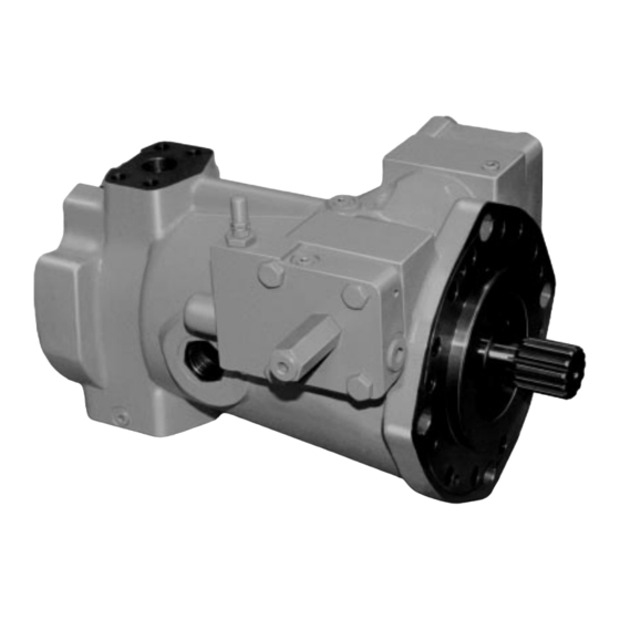
Open circuit piston pump
Hide thumbs
Also See for Premier Series:
- Service information (80 pages) ,
- Service information (50 pages) ,
- Service information (48 pages)
Table of Contents

Related Manuals for Denison Hydraulics Premier Series


Summary of Contents for Denison Hydraulics Premier Series
- Page 1 DENISON HYDRAULICS open circuit piston pumps Premier series P07 & 110 C-mod. service information Publ. LT2-00038-2 replaces S1-AM0018 Revised 5/03 Internet http://www.denisonhydraulics.com E-mail: denison@denisonhydraulics.com www.comoso.com...
-
Page 2: Table Of Contents
"O" rings necessary for total seal replacement may be obtained by ordering Seal Kit . These seals are suitable for petroleum base fluids. For fire resis- tant fluids contact DENISON HYDRAULICS, Inc. or their authorized distributors to obtain the appropriate seal kit number. -
Page 3: Port Identification
IDENTIFICATION OF PORTS AND ADJUSTMENTS “DG” “XG” “AG” with Compensator Override CCW ROTATION SHOWN “C2” FLUID CONNECTIONS ......DESCRIPTION..................P07 ... . .P110 PORT A ..INLET ..................3” SAE CODE 61 . . .3” SAE CODE 61 5/8-11 SCREWS M16-2 SCREWS PORT B ..SYSTEM ................1-1/4”... - Page 4 IDENTIFICATION OF PORTS AND ADJUSTMENTS PRIMARY CONTROLS CLOCKWISE COUNTERCLOCKWISE ROTATION ROTATION "D1" "B" "BG" "LS" ( P110) "LS" (P07) "V1/W1", "V2/W2" LOAD SENSING TORQUE LIMITER "DG" "D" Differential adjustment "V" High pressure Compensator Maximum "C1" flow adjustment volume stop adjustment (far side) High flow Maximum...
- Page 5 IDENTIFICATION OF PORTS AND ADJUSTMENTS PRIMARY CONTROLS CLOCKWISE COUNTERCLOCKWISE ROTATION ROTATION Maximum stroke Secondary adjustment control "D1" "BG" "B" "R" ROTARY SERVO "DG" "C2" far side "D" "X" Range Differential adjustment adjustment "V1" far side (P07) "H" "E" "E" Range (P110) (P110) (P07)
- Page 6 IDENTIFICATION OF PORTS AND ADJUSTMENTS SECONDARY CONTROLS CLOCKWISE COUNTERCLOCKWISE ROTATION ROTATION Differential adjustment Minimum Primary volume stop "C1" "V" control far side "X" Differential adjustment "D1" "B" Compensator "BG" adjustment "*1P" COMPENSATOR OVERRIDE WITH MAXIMUM VOLUME STOP "DG" "D" Maximum High pressure volume stop flow adjustment...
-
Page 7: Start Up Procedure
START UP START UP PROCEDURE FOR NEW INSTALLATION • Read and understand the instruction manual. Identify components and their function. • Visually inspect components and lines for possible damage. • Check reservoir for cleanliness. Drain and clean as required • Check fluid level and fill as required with filtered fluid at least as clean as that recommended. Fill pump case with clean oil prior to starting. -
Page 8: Trouble Shooting Charts
TROUBLESHOOTING Component problems and circuit problems are often interrelated. An improper circuit may operate with apparent success but will cause failure of a particular component within it. The component failure is the effect, not the cause of the problem. This general guide is offered to help in locating and eliminating the cause of problems by studying their effects. - Page 9 TROUBLESHOOTING Effect of Trouble Possible Cause Fault Which Needs Remedy Compensator, Compensator Override Low system pressure Compensator malfunction Dirt in spool orifice Damaged cone or seat Broken differential spring Improperly adjusted differential spring Failure to compensate Differential adjustment Differential set too high Sluggish response Differential adjustment Differential set too low...
-
Page 10: Disassembly
DISASSEMBLY INSTRUCTIONS thread locking com- pound Figure 2 Volume indicator assembly item 52 Figure 1 Exploded view of pump with pressure compensator control www.comoso.com... -
Page 11: Rework Limits
DISASSEMBLY INSTRUCTIONS Disassembly Disassemble only as far as necessary to replace or repair worn parts. If the pump has a rear drive, the mounting adapter and coupling must be removed prior to pump disassembly Refer to figure 3 page 16. Clean outside surface of the pump before disassembly. - Page 12 PUMP PARTS LISTS Ref. Figure 1 Exploded view of pump with pressure compensator control www.comoso.com...
- Page 13 PUMP PARTS LISTS item description part no. part no. qty. P07-SAE P110-ISO shaft assembly keyed, no rear drive S22-15337 S22-15598 a (shaft) 032-91829 032-92197 b (bearing) 230-82216 230-82216 c (seal) 620-82080 230-82080 d (key) 033-71514 032-91429 e (seal retainer) 032-91835 032-91835 keyed, with rear drive S22-16027...
-
Page 14: Parts List
PUMP PARTS LISTS Ref. Figure 1 Exploded view of pump with pressure compensator control PARTS LIST FOR INDICATOR ASSEMBLY item description part no. qty. Pivot nut 032-92491 Indicator 033-70624 fork 032-92653 pivot shaft 032-92492 glyd ring 679-00030 Soc. setscrew, 10-32 x 3/16 312-09030 O-ring, 70 S-1 ARP 114 671-00114... - Page 15 PUMP PARTS LISTS item description part no. part no. qty. P07-SAE P110-ISO dowel pin 324-21610 324-21610 pistons, shoes,retainer assembly S22-16039 S22-16039 (17-1) retainer plate (1 req’d) 032-92453 032-92453 (17-2) pistons and shoes (7 req’d) S22-16031 S22-16031 Belleville washer 032-91827 032-91827 stop 032-91824 032-91824...
-
Page 16: Rear Drive Adapters
REAR DRIVE PARTS LISTS Figure 3 SAE REAR DRIVES code flange SAE 82-2 SAE 82-2 SAE101-2/4 SAE101-2/4 SAE127-2/4 SAE127-2/4 SAE152-4 coupling 16-4 22-4 22-4 25-4 32-4 38-4 44-4 item part (“A”) (modified “A”) (“B”) (“B-B”) (“C”) (“C-C”) (“D”) adapter 032-91900 032-91900 032-91309 032-91309... -
Page 17: Conversion
CONVERSION ROTATION CONVERSION The following parts and assembly are required for changing shaft rotation: • A different barrel and port plate assembly is required. The barrel and port plate are matched assemblies, and should not be ordered separately. The reference part numbers are: CW - Barrel and Port Plate Assembly S22- 16145 CCW - Barrel and Port Plate Assembly... -
Page 18: Reassembly
PUMP REASSEMBLY INSTRUCTIONS SHAFT SEAL REPLACEMENT See illustration Remove worn or damaged seal from retainer. Clean gasket sealant from retainer. Install new seal by applying gasket sealant to retainer and pressing seal in retainer. SEAL KITS ........P07 S22-15646-0 . - Page 19 PUMP REASSEMBLY INSTRUCTIONS Ref. Figure 1 Exploded view of pump with pressure compensator control www.comoso.com...
- Page 20 PUMP REASSEMBLY INSTRUCTIONS 4. Press bearing outer race (11) into housing (7). BARREL AND INNER RACE ASSEMBLY Thread seven M8-1,25 studs into bearing inner race. Lower barrel (14) over studs and seat. If the inner race is heated to 150 F, 65 C, barrel will slide into position without force.
- Page 21 PUMP REASSEMBLY INSTRUCTIONS Ref. Figure 1 Exploded view of pump with pressure compensator control www.comoso.com...
- Page 22 PUMP REASSEMBLY INSTRUCTIONS - Continued - Rocker cradle assembly 20.Apply thread locking compound to two screws (47) and assemble two cam bearings (42) to cradle (6). Torque to 33 lbs-in., 3,8 Nm. THREAD LOCK- ING COMPOUND 33 IN-LB, 3,8 Nm 21.
- Page 23 PUMP REASSEMBLY INSTRUCTIONS Ref. Figure 1 Exploded view of pump with pressure compensator control www.comoso.com...
- Page 24 PUMP REASSEMBLY INSTRUCTIONS CONTROLS ASSEMBLY Install control cap assemblies (50) and (31). The control caps must be positioned on the housing for either CW or CCW pump rotation. See figures 4 & 5 for correct orientation. The control piston (44) was assembled previously for the cor- rect pump rotation.
-
Page 25: Controls
CONTROLS GENERAL The instructions contained in this manual cover complete disassembly and reassembly of the controls. Before pro- ceeding with the disassembly or reassembly of any unit, this manual should be studied in order to become familiar with proper order and parts nomenclature DESCRIPTION OF OPERATION A pilot operated valve spool and sleeve combination is the core of the control function. - Page 26 CONTROLS HYDRAULIC STROKER In the hydraulic stroker, a spring loaded piston is attached to the pin. A control pressure of 50 psi, 3,45 bar causes the piston to commence to move against the spring, to position the pin in proportion to the control pressure, and thus cause the pump to stroke in proportion to control pressure.
-
Page 27: Pressure Compensator
PRESSURE COMPENSATOR CONTROL CCW ROTATION CW ROTATION C10, C50 C20, C80 ITEMS NOT SHOWN PRESSURE COMPENSATOR P110 QTY. ITEM DESCRIPTION PART NO. PART NO. C10/50C20/80 parts list Maximum Stop (Fig. 7) S22-15467 S22-15467 — Maximum Handwheel (Fig. 8) S22-15448 S22-15448 —... - Page 28 PRESSURE COMPENSATOR CONTROL COMPENSATOR DISASSEMBLY 1. See Figure 6. Back off maximum volume screw or handwheel to full displacement. Remove maximum volume screw or handwheel assembly. 2. Remove bolts holding cap to pump. 3. Remove plug (15) and attached parts. Remove spring (11) and spool (18). 4.
- Page 29 PRESSURE COMPENSATOR CONTROL DIFFERENTIAL ADJUSTMENT COMPENSATOR ADJUSTMENT VENT PORT “V” PORT C1 SYSTEM PRESSURE FIGURE 6 P110 ITEM DESCRIPTION PART NO. QTY. PART NO. QTY. PARTS LIST FOR FIGURE 6 Cap-Sleeve Assembly S22-15321 S22-15604 P07 C10 compensator S22-15394 Adjusting Plug 032-91814 032-91814 P110 C10 compensator S22-15623...
-
Page 30: Maximum Volume Stop; Handwheel
MAXIMUM VOLUME STOP PARTS LIST FOR FIGURE 7 maximum volume stop S22-15467 ITEM DESCRIPTION PART NO. QTY. Plug 8HP5N-S 488-35018 O-Ring, 90 S-1 ARP 908 691-00908 Nut, M16 Hex 032-91822 Screw, Soc. Set 311-50001 O-Ring,70 S -1 ARP 115 671- 00115 Figure 7 maximum volume stop PARTS LIST FOR FIGURE 8... -
Page 31: Buck-Up Cap Assembly
BUCK-UP CAP FIGURE 9 Buck-up cap assembly PARTS LIST FOR FIGURE 9 buck-up cap S22-15447 ITEM DESCRIPTION PART NO. QTY. Piston 032-92202 Spring 032-92205 Sleeve 032-92203 Control Cap 032-91832 O-Ring 691-00920 Plug 032-92204 Avseal Plug 447-00026 BUCK-UP CAP DISASSEMBLY 1. See Figure 9. Set maximum volume stop to full displacement. Remove 4 screws holding cap to pump. Caution! Spring load could cause injury! 2. -
Page 32: Torque Limiter
TORQUE LIMITER CONTROL NOT SHOWN CCW ROTATION CW ROTATION NOT SHOWN J/K10, 50 J/K20, 80 ITEMS TORQUE LIMITER NOT SHOWN P110 QUANTITY PARTS LIST ITEM DESCRIPTION PART NO PART NO. J10 K10 J20 K20 torque limiter Maximum Stop (Fig. 7) S22-15467 S22-15467 —... - Page 33 TORQUE LIMITER CONTROL DIFFERENTIAL ADJUSTMENT COMPENSATOR ADJUSTMENT VENT PORT “V” PORT C1 SYSTEM PRESSURE FIGURE 10 TORQUE LIMITER CAP P110 PARTS LIST FOR FIGURE 10 ITEM DESCRIPTION PART NO. QTY. PART NO. QTY P07 torque limiter cap S22-15407 P110 torque limiter cap S22-15607 Cap-Sleeve Assembly S22-15408 S22-15608...
- Page 34 TORQUE LIMITER CONTROL FIGURE 11 Torque Limiter PARTS LIST FOR FIGURE 11 P110 QTY. P07 code J10,J50 S22-15401 ITEM DESCRIPTION PART NO. PART NO. P07 code J20,J80 S22-15627 Cap (Figure 10) S22-15407 S22-15607 P07 code K10K50, S22-15629 Screw 032-91461 032-91461 P07 code K20K80, S22-15635 Clevis pin 321-40000 321-40000...
- Page 35 TORQUE LIMITER CONTROL DISASSEMBLY 1. See Figure 11. Remove 2 screws holding torque limiter body (16) to cap assembly (1). 2. Remove all parts from torque limiter body (16) except pin (30) and arm assembly (28). It is not necessary to remove these parts unless broken or worn.
-
Page 36: Load Sensing Control
LOAD SENSING PRESSURE COMPENSATOR CONTROL CCW ROTATION CW ROTATION L20, L80 L10, L50 ITEMS LOAD SENSING CONTROL NOT SHOWN parts list P110 QTY. ITEM DESCRIPTION PART NO. PART NO. L10, L50 L20, L80 Maximum Volume Stop (Fig. 7) S22-15467 S22-15467 —... - Page 37 LOAD SENSING PRESSURE COMPENSATOR CONTROL FIGURE 12 load sensing compensator control PARTS LIST FOR FIGURE 12 P110 LOAD SENSING COMPENSATOR ITEM DESCRIPTION PART NO. QTY PART NO. QTY P07 L1* S22-15402 Cap-Sleeve Assembly S22-15143 S22-15176 P07 L2* S22-15628 Adjusting Plug 032-91814 032-91814 P110 L1* S22-15625...
- Page 38 LOAD SENSING PRESSURE COMPENSATOR CONTROL DISASSEMBLY 1. See Figure 12 Back off maximum volume screw or handwheel to full displacement. Remove maximum volume assembly. 2. Remove bolts holding cap to pump. 3. Remove isolation valve (29) from block (28). Remove plug (15) and attached parts. Remove spring (11) and spool (18). 4.
-
Page 39: Load Sensing Torque Limiter
LOAD SENSING TORQUE LIMITER CONTROL NOT SHOWN CCW ROTATION CW ROTATION NOT SHOWN V/W10, 50 V/W20, 80 ITEMS PARTS LIST load sensing torque limiter NOT SHOWN P110 QUANTITY ITEM DESCRIPTION PART NO PART NO. V10* W10* V20** W20** Maximum Volume Stop (Fig. 7) S22-15467 S22-15467 —... - Page 40 LOAD SENSING TORQUE LIMITER CONTROL TORQUE 75 FT-LBS 103 Nm THREAD LOCKING COMPOUND FIGURE 13 Load Sensing Torque Limiter PARTS LIST FOR FIGURE 13 P110 QTY. ITEM DESCRIPTION PART NO. PART NO. P07 code V10, V50, S22-16186 Cap (Figure 14) S22-16177 S22-16179 P07 code W10, W50, S22-16187 Adapter...
- Page 41 LOAD SENSING TORQUE LIMITER CONTROL DISASSEMBLY 1. See Figure 13. Remove 2 screws holding torque limiter body (16) to cap assembly (1). 2. Remove all parts from torque limiter body (16) except pin (30) and arm assembly (28). It is not necessary to remove these parts unless broken or worn.
- Page 42 LOAD SENSING TORQUE LIMITER CONTROL differential adjustment vent connection “V” compensator adjustment port C1 system pressure Ref. Figure 14 Load Sensing Torque limiter cap P110 PARTS LIST FOR FIGURE 14 ITEM DESCRIPTION PART NO. QTY. PART NO. QTY P07 load sensing torque limiter cap S22-16177 Cap-Sleeve Assembly S22-16178...
-
Page 43: Rotary Servo
ROTARY SERVO CONTROL NOT SHOWN CCW ROTATION NOT SHOWN R10* R1J, R1K** R1P*** CW ROTATION NOT SHOWN PARTS LIST rotary servo P110 QUANTITY ITEM DESCRIPTION PART NO. PART NO. R10* R1J** R1K**R1P*** #Rotary Servo (Fig. 15) S22-16200 S22-16199 #Control Cap (Fig.26) S22-15325 S22-15613 —... - Page 44 ROTARY SERVO CONTROL HYDRAULIC SEALANT TORQUE 5 FT-LB, 6,8 Nm USE THREAD LOCKING COMPOUND FIGURE 15 TORQUE rotary servo 75 LB • FT 102 Nm PARTS LIST FOR FIGURE 15 P110 ROTARY SERVO ITEM DESCRIPTION PART NO. QTY. PART NO. QTY. P07 S22-16200 Cap (Figure 16) S22-16063...
- Page 45 ROTARY SERVO CONTROL DISASSEMBLY 1. See Figure 15. Remove 2 screws holding body (16) to cap assembly (1). 2. Remove all parts from body (16) except pin (30) and arm assembly (28). It is not necessary to remove these parts unless broken or worn.
- Page 46 ROTARY SERVO CONTROL PORT “C2” DIFFERENTIAL ADJUSTMENT Ref. Figure 16 Servo cap P110 PARTS LIST FOR FIGURE 16 ITEM DESCRIPTION PART NO. PART NO. QTY. P07 servo cap S22-16063 Cap /Sleeve S22-16065 S22-16066 P110 servo cap S22-16064 Plug, SAE-4, 1/4 BSPP 488-35061 447-01004 O-ring, 90 S-1 ARP 904...
-
Page 47: Hydraulic Stroker
HYDRAULIC STROKER CONTROL NOT SHOWN CCW ROTATION NOT SHOWN H10* H1P*** H1J, H1K** CW ROTATION NOT SHOWN PARTS LIST hydraulic stroker P110 QUANTITY ITEM DESCRIPTION PART NO. PART NO. H10* H1J** H1K**H1P*** #Hydraulic Stroker (Fig. 17) S22-16202 S22-16201 #Control Cap (Fig.26) S22-15325 S22-15613 —... - Page 48 HYDRAULIC STROKER CONTROL FIGURE 17 hydraulic stroker PARTS LIST FOR FIG. 17 P110 P07 hydraulic stroker S22-16202 ITEM DESCRIPTION PART NO. QTY. PART NO. QTY P110 hydraulic stroker S22-16201 Cap (Figure 16) S22-16063 S22-16064 Screw 032-91461 032-91461 Clevis pin 321-40000 321-40000 Spring, Compression 032-92100...
- Page 49 HYDRAULIC STROKER CONTROL DISASSEMBLY 1. See figure 17. Remove 2 screws holding body (16) to cap assembly (1). 2. Remove all parts from body (16) except pin (30) and arm assembly (28). It is not necessary to remove these parts unless broken or worn.
-
Page 50: Electrohydraulic Stroker
ELECTROHYDRAULIC STROKER CONTROL NOT SHOWN CCW ROTATION NOT SHOWN E10* E1J, E1K** E1P*** CW ROTATION NOT SHOWN PARTS LIST electrohydraulic stroker P110 QUANTITY ITEM DESCRIPTION PART NO. PART NO. E10* E1J** E1K** E1P*** #Electrohydraulic Stroker (Fig. 18) S22-16057 S22-16060 #Control Cap (Fig.26) S22-15325 S22-15613 —... - Page 51 ELECTROHYDRAULIC STROKER CONTROL FIGURE 18 Electrohydraulic Stroker P110 PARTS LIST FOR FIGURE 18 P07 electrohydraulic stroker ITEM DESCRIPTION PART NO. QTY. PART NO. QTY. Cap (Figure 16) S22-16063 S22-16064 S22-16204 Screw 032-91461 032-91461 P110 electrohydraulic stroker Clevis pin 321-40000 321-40000 S22-16203 Spring, Compression 032-92100...
- Page 52 ELECTROHYDRAULIC STROKER CONTROL DISASSEMBLY 1. See Figure 18. Remove 3 screws (37) holding block (36) to body (16). 2. Remove 2 screws holding body (16) to cap assembly (1). 3. Remove all parts from body (16) except pin (30) and arm assembly (28). It is not necessary to remove these parts unless broken or worn.
- Page 53 ADJUST FOR ZERO FLOW AT 175 MA ELECTRICAL COMMAND PORT “E”, P07 PORT “E”, P110 PORT “X” SERVO INLET PROPORTIONAL VALVE GAGE PORT “H” www.comoso.com...
-
Page 54: Pq Control (Pending)
PQ HIGH RESPONSE CONTROL PQ CONTROL IN PROCESS OF DEVELOPMENT www.comoso.com... - Page 55 PQ HIGH RESPONSE CONTROL PQ CONTROL IN PROCESS OF DEVELOPMENT www.comoso.com...
- Page 56 PQ HIGH RESPONSE CONTROL PQ CONTROL IN PROCESS OF DEVELOPMENT www.comoso.com...
- Page 57 PQ HIGH RESPONSE CONTROL PQ CONTROL IN PROCESS OF DEVELOPMENT www.comoso.com...
-
Page 58: Control Tubing; Control Cap
SECONDARY CONTROLS Figure 24 cw rotation control tubing PARTS LIST FOR FIGURE 24 cw rotation control tubing S22-16035 (P07) S22-16037 (P110) ITEM DESCRIPTION PO7 PART NO. P110 PART NO. QTY. Servo tube w/nut & sleeve S22-16032 S22-16077 O-ring, 90 S-1 691-00906 691-00113 Elbow fitting... -
Page 59: Compensator Override Control
COMPENSATOR OVERRIDE CONTROL differential adjustment compensator adjustment vent port “V” port “C1” Figure 27 system Compensator override control pressure PARTS LIST FOR FIGURE 27 P110 compensator override control ITEM DESCRIPTION PART NO. QTY. PART NO. QTY P07 compensator override S22-16205 Cap-Sleeve Assembly S22-16043 S22-16044... - Page 60 COMPENSATOR OVERRIDE CONTROL DISASSEMBLY 1. See Figure 27. Remove tube line to cap. 2. Remove maximum volume stop assembly (items 20, 21, 22, 23, 24). 3. Remove cap assembly. 4. Remove plug (15) and attached parts. Remove spring (11) and spool (18). 5.
-
Page 61: Torque Limiter Override Control
TORQUE LIMITER OVERRIDE COMPENSATOR ADJUSTMENT VENT PORT “V” PORT C1 SYSTEM PRESSURE FIGURE 28 torque limiter override cap P110 PARTS LIST FOR FIGURE 28 ITEM DESCRIPTION PART NO. QTY. PART NO. QTY torque limiter override cap Cap-Sleeve Assembly S22-16045 S22-16046 P07 cap S22-16049 Adjustment. - Page 62 TORQUE LIMITER OVERRIDE FIGURE 29 TORQUE LIMITER OVERRIDE P110 QTY. PARTS LIST FOR FIGURE 29 ITEM DESCRIPTION PART NO. PART NO. torque limiter override Cap (Figure 28) S22-16049 S22-16050 P07 code J, S22-16207 Screw 032-91461 032-91461 P07 code K, S22-16209 Clevis pin 321-40000 321-40000...
- Page 63 TORQUE LIMITER OVERRIDE Disassembly 1. See figure 29. Remove 2 screws holding torque limiter body (16) to cap assembly (1). 2. Remove all parts from torque limiter body (16) except pin (30) and arm assembly (28). It is not necessary to remove these parts unless broken or worn.
-
Page 64: Testing
TEST PROCEDURE Test Conditions: (If using service facility test stand) Fluid: Mobil 4259 DE (ISO V6-32 or equivalent) RPM: 1450 or 1750 ± 50 RPM Inlet Temperature: 120 F ± 10 F., 49 C ± 4 Inlet Condition: Atmospheric to + 5 psi, 0,345 bar Case Pressure: 25 psi ±5 psi, 1,72 bar ±... - Page 65 TEST PROCEDURE minimum displacement adjustment, under plug cylinder gage port “C2” servo input shaft differential adjustment under cover set maximum displacement servo port “X” gage port “V1” gage port “XG” ROTARY SERVO CONTROL CAP TEST CIRCUIT ROTARY SERVO WITH COMPENSATOR OVERRIDE ROTARY SERVO TEST (continued) Plumb servo supply (5 gpm, 19 lpm minimum at 1500 psi, 103 bar maximum) to control port “X”.
-
Page 66: Compensator Test
TEST PROCEDURE compensator adjustment port “C1” differential adjustment vent “V” TEST CIRCUIT COMPENSATOR OVERRIDE CAP COMPENSATOR OVERRIDE ROTARY SERVO INPUT COMPENSATOR TEST Outlet relief valve should be set to minimum pressure. If the pump contains a servo, hydraulic or electrohydraulic stroker control, test that control first, (pg. 64, 68 or 69) then set the control to give full displacement on the pump. -
Page 67: Load Sensing Test
TEST PROCEDURE Raise compensator from minimum to maximum outlet pressure. At each condition, increase the outlet pressure until the pump fully de-strokes. At no time should the outlet pressure vary over 150 psi, 10,3 bar from the compensator set- ting. The control should be steady and stable at all conditions. Calculate compensator leakage by subtracting leakage flow at full flow from leakage flow fully compensated. -
Page 68: Hydraulic Stroker Test
TEST PROCEDURE servo pressure gage port “XG” minimum displacement adjustment, under plug zero flow adjustment differential adjustment under cover control port “H” control port “H” cylinder gage port “C2” “V1” P110 servo pressure HYDRAULIC STROKER CAP port “X” TEST CIRCUIT HYDRAULIC STROKER COMPENSATOR OVERRIDE HYDRAULIC STROKER,... -
Page 69: Electrohydraulic Stroker Test
TEST PROCEDURE minimum displacement adjustment, under plug port “E”, P07 port “E”, P110 port “X” zero adjustment differential adjustment under cover port “C2” port “H” port “V1” port “XG” TEST CIRCUIT ELECTROHYDRAULIC STROKER CAP ELECTROHYDRAULIC STROKER COMPENSATOR OVERRIDE ELECTROHYDRAULIC STROKER TEST Before testing electrohydraulic stroker, disable the compensator or torque limiter override, if applicable, by turning the compensator differential adjustment fully in. -
Page 70: Torque Limiter And Torque Limiter Override Test
TEST PROCEDURE TORQUE LIMITER AND TORQUE LIMITER OVERRIDE TEST The torque limiter design is a compensator with a means of vary- ing pump displacement with pressure in this manner: The com- pensator vent port applies pressure to a pin. The pin moves against two independently adjustable springs. - Page 71 TEST PROCEDURE Set the compensator to 3000 psi, 207 bar, 6000 psi, 414 bar, and 7250 psi, 500 bar. (One turn approximately equals 2000 psi, 138 bar) At each condition, increase the outlet pressure until the pump fully de-strokes. At no time should the outlet pressure vary more than 150 psi, 10,3 bar from the compensator setting.
-
Page 72: Load Sensing Torque Limiter Test
TEST PROCEDURE LOAD SENSING TORQUE LIMITER Caution: Load sensing control is limited to 5000 psi, 345 bar maximum pressure. Pump should be connected to speed control valve, load sensing line and load valve as shown. Install gages on outlet pressure and “V” capable of measuring pressure difference to 10 psi, 0,69 bar. - Page 73 TEST PROCEDURE Open load valve slowly, to drop outlet pressure toward minimum. Flow shall remain constant within 2 gpm, 7,6 lpm at all pressures. Adjust the speed control valve till flow is at a low value. Note flow. Raise and lower outlet pressure by closing and opening the load valve.
-
Page 74: Pq Control Test (Pending)
TEST PROCEDURE PQ CONTROL IN PROCESS OF DEVELOPMENT www.comoso.com... -
Page 75: Pump Test
TEST PROCEDURE FINAL PUMP TEST Operate the pump with the following outlet pressures for the times indicated. 3000 psi ± 100 psi, 207 bar ± 6,9 bar 2 minutes minimum 5000 psi ± 100 psi, 345 bar ± 6,9 bar 1 minute minimum 6000 psi ±... -
Page 76: Tools
ASSEMBLY TOOLS 7.25 1.761 (184,1) (44,74) (9,65) 3.25 slot each side (82,55) (19,05) .12 (3,05) for M6 socket 1.00 3.00 head cap screw (25,4) (76,2) Press fit for 1/2” 1.50 (12,7mm) dowel pin x (38,1) 4” (101,6mm) long (Lifting tool) barrel &... -
Page 77: Characteristics
TYPICAL CHARACTERISTICS Specification Term P110 • displacement at maximum angle................../rev. /rev 109,8 109,8 • pressure continuous ......................6000 6000 • pressure intermittent (not to exceed 6 sec./minute) ............7250 7250 • speed, @ atmospheric inlet ....................2450 2450 maximum with boost 3000 3000 •... - Page 78 INSTALLATION PROCEDURES, AND TECHNICAL SPECIFICATIONS AND LIMITS GENERAL The DENISON HYDRAULICS P07/P110 Series is a variable displacement open circuit axial piston pump with advance pumping and control concepts. MOUNTING This pump is designed to operate in any position. The pump shaft must be in alignment with the shaft of the prime mover and should be checked with a dial indicator.
-
Page 79: Ordering Code
(available on C, J, K, L, V & W primary controls only) 3-Maximum volume screw with cam position potentiometer * Minimum torque values to maintain 5000 psi, 345 bar at (pending) 1800 rpm. Consult DENISON Hydraulics for minimums 4-Maximum volume screw with cam position LVDT at lesser pressures and speeds. (pending) - Page 80 SALES & SERVICE WORLDWIDE International Distributors Australia Germany Singapore In Europe: DENISON HYDRAULICS Pty. Ltd. DENISON HYDRAULIK GmbH DENISON HYDRAULICS S.E.A. Pte. Cyprus 41-43 St. Hillers Road Herderstrasse 26 Ltd. Czech Republic P.O. Box 192 D-40721 Hilden No. 11 Lorong Tukang Dua Eastern Europe Auburn, N.S.W.
Need help?
Do you have a question about the Premier Series and is the answer not in the manual?
Questions and answers