Denison Hydraulics Goldcup Series Service Information
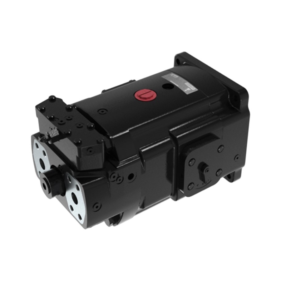
Axial piston pump
Hide thumbs
Also See for Goldcup Series:
- Service information (24 pages) ,
- Installation & overhaul instructions (24 pages) ,
- Service information (48 pages)

Related Manuals for Denison Hydraulics Goldcup Series


Summary of Contents for Denison Hydraulics Goldcup Series
- Page 1 DENISON HYDRAULICS axial piston pump goldcup series P24P/S E-mod., P30P/S B-mod. service information Publ. LT3-00032-2-A 8/03 www.comoso.com...
- Page 2 The product information, specifications, and descriptions contained in this publication have been compiled for the use and convenience of our customers from information furnished by the man- ufacturer; and we can not, and do not, accept any responsibility for the accuracy or correctness of any description, calculation, specification, or information contained herein.
-
Page 3: Table Of Contents
CONTENTS PAGE technical characteristics fluid connections seal kits introduction description mounting rear pump mounting shaft information piping recommended fluids viscosity viscosity index temperature alternate fluids fluid cleanliness comparison of solid contamination classification system filling case service information maintenance start up procedures for new installations trouble shooting assembly tool drawings T1,T2,T3, and T4 disassembly procedures... -
Page 4: Technical Characteristics
/rev. 501,4 •pressure, continuous 5000 5000 •speed max. continuous at full stroke rpm 2100 1800 consult DENISON HYDRAULICS for higher speeds •flow, ports A or B at 1500 r pm 159.7 198.7 theo. at max. displ. 604,6 752,1 at 1800 rpm 191.7... -
Page 5: Fluid Connections
SEAL KITS FLUID CONNECTIONS Refer to page 40 for specifications SEAL KITS seal kit, P24/30 complete (includes control seals) see chart below valve block seal kit (all) S23-17338-⊕Κ shaft seal kit see chart below shaft seal 623-00015-5K controls seal kit (all – input & output) S23-17000-⊕Κ... -
Page 6: Introduction
INSTALLATION INTRODUCTION The DENISON HYDRAULICS Goldcup 24 and 30 axial piston pumps f eature advance design concepts which are time proven and provide for advanced pumping and control concepts. The instructions contained in this manual cover complete disassembly and re-assembly of the unit. Before proceeding with the disassembly or reassembly of any unit, this manual should be studied in ordered to become f amiliar with proper order and parts nomenclature. -
Page 7: Recommended Fluids
The fluid recommended for use in these pumps has a petroleum base and contains agents which provide oxidation inhibition and anti-rust, anti-foam and de-aerating properties as described in DENISON HYDRAULICS standard HF-1. Where anti-wear additive fluids are specified, see DENISON HYDRAULICS standard HF-0. -
Page 8: Filling Case
INSTALLATION FILLING CASE It is essential to make certain that the case (pump housing) is as full of fluid as possi- ble and remains full during operation and at rest. Always fill to the highest available point. Remove a plug or screw and allow the oil to escape through this point. -
Page 9: Trouble Shooting
TROUBLE SHOOTING TROUBLESHOOTING Component problems and circuit problems are often interrelated. An improper circuit may operate with apparent success but will cause failure of a particular component within it. The component failure is the effect, not the cause of the prob lem. This general guide is offered to help in locating and eliminating the cause of the problems by studying their effects. - Page 10 TROUBLESHOOTING TROUBLESHOOTING effect of trouble possible cause fault which needs remedy pressure shocks cogging load mechanical considerations (continued) worn relief valve needed repairs worn compen- needed repairs sator slow response in replace or relocate check valves servo pressure increase pressure and check pressure drop too low to through servo filter maintain firm...
- Page 11 ASSEMBLY / DISASSEMBLY TOOLS Barrel H.D. adjustment tool No longer used. T2 Material - cold roll steel Replenishing and servo pump removal tool Shaft seal installation tool - rear adapter www.comoso.com...
-
Page 12: Disassembly Procedures
UNIT DISASSEMBLY INTRODUCTION The instructions contained in this section cover a complete teardown of the subject pump. Disassemble only as far as necessary to replace or repair any worn parts. DISASSEMBLY CAUTION: On 24 series units relax barrel holddown prior to removal of shaft seal or main shaft. - Page 13 UNIT DISASSEMBLY SERVO/REPLENISH PUMP NOTE: This is a complete vane cartridge assembly and removed in one step. A puller tool T3 is recommended. AND BARREL HOLDDOWN (continued) Remove sealing washer (1). (24 series barrel holddown) See figure 4. Remove holddown lock retainer ring (8). (Use internal snap ring pliers.) See figure 9.
-
Page 14: Rework Limits Of Wear Parts
UNIT DISASSEMBLY (30 series barrel holddown See figure 3. Push tubes (4) out of housing slots and to ward barrel, do not bend or damage them. continued) See figure 6. Lift housing (4) over tubes and barrel assembly and remove. Mounting flange must be driven from the housing due to tight fit. - Page 15 UNIT DISASSEMBLY REWORK LIMITS OF WEAR IMPORTANT: The port plate finish must be 8 microinches, .0203 micrometer both faces, flat within PARTS 0.00006”, 0,0015 mm and parallel within 0.001”, 0,0254 mm total indicator reading. (continued) The creep plate wear face finish must be 5 microinches, .0127 micrometer, flat within 0.0005”, 0,0127 mm and parallel to the backside within 0.001”, 0,0254 mm total indica- tor reading.
-
Page 16: Assembly Procedures
ASSEMBLY PROCEDURE CLEANING AND INSPECTION All parts must be inspected and be free of mater ial defects, dirt, scratches or any foreign material. All parts must be cleaned with a suitable cleaning solvent and all holes and passages blown out with dry, clean, compressed air. After cleaning and inspection, all par ts must be covered with a light film of oil and pro- tected from dirt and moisture. -
Page 17: Cam And Cradle Assemblies
ASSEMBLY PROCEDURE CAM-CRADLE ASSEMBLIES S23-12478 is for RH CW rotation pumps with “B” suffix input control on right side. items 6 through (less item 24) 25, S23-12479 is for LH CCW rotation pumps with “B” suffix input control on right side. figure 2 S23-12476 is for RH CW rotation pumps with “A”... -
Page 18: Rocker Cam
ASSEMBLY PROCEDURE ROCKER CAM ASSEMBLY See figure 2. Position the cradle (18) on a clean surface with the large flat side do wn. Lightly oil curved surface of cradle. Position rocker cam (21) on the cradle, aligning match marks made during disassembly. Place o-ring (23c) on vane spacer (23d) and inser t in the vane seal (23b). -
Page 19: Piston And Shoe
ASSEMBLY PROCEDURE ROCKER CAM ASSEMBLY Install servo plate (10) to stem (6) with tw o #10-24 button head screws (8). Torque (continued) to 30 lbs-in., 3,4 Nm. Install two set screws (25) in servo plate. Torque to 25 lbs-in., 2,8 NOTE: The balance plate cannot be assembled to the rocker cam until after the housing assembly installation has been completed See figure 7. - Page 20 MOUNTING FLANGE, PARTS LIST FOR FIGURE 3 item description part no. quantity CAM & CRADLE, BARREL & AUXILIARY SHAFT ASSEMBLY barrel & aux. shaft assembly see fig.4 or 4.1 (continued) override tubes item 24 see fig. 2 male elbow 473-15041 tube assembly P24 S13-44469 tube assembly P30...
- Page 21 ASSEMBLY PROCEDURE BARREL AND AUXILIARY See figure 4.1. Install auxiliary shaft (2) large spline end first into counterbore in f ace of barrel and engage barrel spline. DRIVE SHAFT 30 SERIES Slide holddown spring assembly (3) onto shaft (2). Install spring retainer (4) into counterbore.
-
Page 22: Mechanical Shaft Seal
ASSEMBLY PROCEDURE HOUSING, END CAP, CAM AND See figure 6. Install new gasket (3) over the dowel pin in the mounting flange. Do not use gasket compound. BARREL ASSEMBLY Insert two socket hd. cap screws (6) through holes in balance stem (7). Attach balance stem to stroking control assembly. - Page 23 ASSEMBLY PROCEDURE SEAL ASSEMBLY See figure 7. NOTE: 24 series only - to replace shaft seal only: Remove unit for disassembly. Some units require removing an adapter housing and external pump. Follow steps removing the internal auxiliary pump and seal plate see figure 10. Remove retaining ring (8), figure 4.
-
Page 24: Counterbalance Plate
ASSEMBLY PROCEDURE PARTS LIST FOR FIGURE 7 item description part no. quantity No. 3 splined shaft assy. S23-12474 see figure 1 No. 2 keyed shaft assy. S23-12475 see figure 1 seal retainer 033-57472 shaft seal 623-00015 seal retainer o-ring 671-00246 hex. -
Page 25: Port Block Installation
ASSEMBLY PROCEDURE CONTROL COVER ASSEMBLY Install the cover assemblies (14) & (15) over the dowel pins on the housing pads and (Continued) secure with seal (12) and screws (13). Torque to 30 lbs-ft., 40,8 Nm. PORT BLOCK ASSEMBLY See figure 8. Position the port block (1) on a clean flat surf ace with two open ports up. The finished faces must not be scratched or damaged. - Page 26 ASSEMBLY PROCEDURE PARTS LIST FOR FIGURE 9 item description part no. quantity hex. hd. cap screw P24P 306-40221 hex. hd. cap screw P30P 306-40230 port block assy. S23-15105 port block assy. w/shuttle (S) S23-15127 port plate pin 324-21610 R.H. port plate 24 033-71752 R.H.
-
Page 27: Barrel Holddown And Auxiliary Pump 30 Series
ASSEMBLY PROCEDURE BARREL HOLDDOWN AND See figure 4.1 & 10. Use special tool T2 and slip over auxiliary shaft and engage dow- els into holddown screw assembly (5), figure 4.1. Carefully tighten clockwise until hold- AUXILIARY PUMP 30 SERIES down screw assembly bottoms out. NOTE: The main drive shaft must be held to prevent barrel assembly from turning. - Page 28 ASSEMBLY PROCEDURE Valve block ass’y. See fig. 12, 13 use item 12, for mounting fig. 12 See figure 13 for its mtg. screws Torque to 30 lbs-ft. (40,8 Nm) 20 & 21 20 & 21 FIGURE 10 PARTS LIST FOR FIGURE 10 item description part no.
-
Page 29: Rear Drive Adapter
ASSEMBLY PROCEDURE PARTS LIST FOR FIGURE 10 (continued) item description part no. screw 1/2-13 x 2-1/2 358-20280 shuttle valve assembly S23-11966 plug, str. thd. 488-35041 o-ring 691-00906 o-ring SAE-B 671-00155 o-ring SAE-C 671-00159 rear drive adapter See figure 10. A special tool T4 refer assembly tools is required to press shaft seal (13) into SAE-B adapter. - Page 30 ASSEMBLY PROCEDURE shuttle valve assembly (continued) PARTS LIST FOR FIGURE 11, S23-11966 item description part no. quantity shuttle block 033-57752 pilot valve external drain S26-22865 spool 033-57180 spring stop washer 033-57182 sleeve 036-27549 piston 036-32902 spring 036-27547 spring 033-57181 o-ring 691-00125 o-ring 691-00026...
-
Page 31: Shuttle Valve Adapter
ASSEMBLY PROCEDURE shuttle valve adapter See figure 10. Lubricate tetraseals (15) and o-ring (16) and place in c’bores on shuttle valve adapter’s (17) mounting surface. Carefully attach shuttle adapter to por t block using soc. hd. cap screws (18). Torque to 75 lbs-ft., 102 Nm. - Page 32 ASSEMBLY PROCEDURE VALVE BLOCK ASSEMBLY Using a small bladed screw driver, thread the pilot replenishing relief v alve assembly (36) into valve block and lightly tighten in place. Do not over tighten. Over tightening Figure 12 can cause sides of slot to break no w or at next removal. (continued) Lubricate o-ring (4) and install on plug (25) and tighten plug in place .
- Page 33 ASSEMBLY PROCEDURE VALVE BLOCK ASSEMBLY Figure 12 (continued) Assembly No: S23-12742 P24P S23-12794 P30P S23-12770 P24S S23-12795 P30S S23-12796 P24/30P w/9A control FIGURE 12 www.comoso.com...
-
Page 34: Valve Block For Servo Valve
ASSEMBLY PROCEDURE VALVE BLOCK ASSEMBLY FOR NOTE: Prior to assembly of reconditioned parts, check finish of gasket surface on valve block and retainer. Must have 60 rms finish with no grinding marks SERVO VALVE MOUNTING which might carry oil to outside surface. If lapping is necessary, check depth Figure 13 of pockets for valve seats after lapping. - Page 35 ASSEMBLY PROCEDURE VALVE BLOCK ASSEMBLY FOR Lubricate o-ring (19) and install on plug (20) and tighten plug in place . SERVO VALVE MOUNTING Lubricate o-rings (22) and install on plugs (23) and tighten plug in place . Figure 13 (continued) Lubricate o-rings (4) and install on plugs (25) and tighten plug in place .
- Page 36 ASSEMBLY PROCEDURE VALVE BLOCK ASSEMBLY FOR PARTS LIST FOR FIGURE 13 item description part no. quantity SERVO VALVE MOUNTING valve block 033-91335 Figure 13 check valve assembly S13-40266 (continued) orifice plug 033-91249 o-ring 691-00903 seat 033-70508 soc. hd.screw 5/16-24 x 1” lg. 312-13160 hex.
- Page 37 ASSEMBLY PROCEDURE VALVE BLOCK ASSEMBLY FOR SERVO VALVE MOUNTING Figure 13 (continued) closed loop w/servovalve adapter & on/off compensator control Assembly No: S23-12776 P24P/P30P & P24S/P30S Assembly No. S23-12798 P24P/P30P & P24S/P30S w/servovalve adapter & on/off compensator control FIGURE 13 www.comoso.com...
-
Page 38: Test Procedure
TEST PROCEDURE GENERAL REQUIREMENTS Maximum runout between pump shaft and electric motor shaft .003”, .076 mm total indicator reading. Electric motor speed - 1800 r pm. Inlet temperature - 120 -140 F, 500-580C. Inlet condition - main pump 24 series 150 psi min., 10,3 bar min. 30 series 225 psi min., 15,5 bar min. -
Page 39: Alternate Test Procedure
TEST PROCEDURE BASIC PUMP TEST Set pump to compensate at minim um psi. Check and record replenishing and ser vo (continued) pressure. Servo pressure - minus replenish pressure: 30/24 series: 160 to 220 psi, 11 to 15 bar *Replenish pressure - minus case pressure: Std –... -
Page 40: Control Test - Refer To Control Service Manual S1-Am030
TEST PROCEDURE BASIC PUMP TEST Mount pump on test stand. Connect system lines and inter nal vane pump inlet to pump. Fill pump case with clean oil. Dry all oil from pump to per mit checking for external leaks. Start electric motor. Jog several times before continuous running. Rotate pump input control shaft. - Page 41 FLUID CONNECTION NOMENCLATURE item description (For ISO circuits Figures 14 & 15) piston pump vane chambers rotary servo auxiliary pump servo pressure relief valve (modulated by operating pressure) replenish pressure relief valve sequence valve compensator pilot valve override pressure valve or servo pressure sequence valve replenish ring check valve external auxiliary boost pump...
-
Page 42: Hydraulic Circuit P24/30P
CIRCUITS Figure 14 P24/30P www.comoso.com... -
Page 43: Hydraulic Circuit P24/30S
CIRCUITS Figure 15 P24/30S www.comoso.com... -
Page 44: Installation Drawings
INSTALLATION DRAWING "AG1" REF. 1.06 "H2" SAE-6 STR THD - ALT. SERVO INLET -13UNC x DEEP 2-PLACES (26,9) 4-PLACES "VA" REF. 16.34 5.53 18.80 AIR BLEED PORT FOR FILLING CASE (414,9) (140,3) "V" SAE-4 STR THD - COMPENSATOR VENT REF. ON VERTICAL MTD. - Page 45 INSTALLATION DRAWING 1.06 "AG1" REF. -13UNC x DEEP "H2" SAE-6 STR THD - ALT. SERVO INLET (26,9) 4-PLACES 2-PLACES 17.34 5.53 "VA" REF. AIR BLEED PORT FOR FILLING CASE (440,3) (140,3) 19.80 REF. "V" SAE-4 STR THD - COMPENSATOR VENT OPTIONAL KEYED SHAFT (502,8) ON VERTICAL MTD.
- Page 46 INSTALLATION DRAWING 23.83 1.00 -11 UNC x DEEP 605.3 2.23 (25,4) 2.15 EQUALLY SPACED, AS SHOWN, "G" SAE-12 STR THD COUPLING DEPTH 56,5 7.13 AUX. PUMP (SERVO & REPLEN.) BOLT CIRCLE, 4-PLACES 54,5 (181,0) OUTLET TO EXTERNAL FILTER SAE-C INVOLUTE SPLINE DATA J498-B 1969 FLAT ROOT SIDE FIT EXTERNAL CLASS-1 12/24 PITCH 1.85...
- Page 47 INSTALLATION DRAWING 8.14 (206,7) 19° 19° "Y" VOLUME ADJ. SEE CHART -A- CONTROL MTG. POSITION MAX. MAX. CONTROL PUMP FIND PUMP ROTARY SERVO INPUT PORT PORT "X" VOL. ADJ. "Y" VOL. ADJ. OPTION PACKAGE FIGURE ROT. "A" "B" SPRG. OFF-SET TO FULL P24P CCW ROT.
- Page 48 INSTALLATION DRAWING 8.14 (206,8) "Y" CONTROL PORT 1.00 -27 DRYSEAL N.P.T.F. (25,4) "X" CONTROL PORT 1.00 NOTES: -27 DRYSEAL N.P.T.F. (25,4) 1. FOR DIMENSIONS & PORT IDENTIFICATIONS NOT SHOWN SEE THE APPROPRIATE BASIC PUMP INSTALLATION: P24P BASIC INSTALLATION (LESS CONTROLS) 23-9922-D P30P BASIC INSTALLATION (LESS CONTROLS) 23-9913-D 2.
- Page 49 INSTALLATION DRAWING 8.14 (206,7) 19° 19° NOTES: MAX. MAX. 1. FOR DIMENSIONS & PORT IDENTIFICATIONS NOT SHOWN SEE THE APPROPRIATE BASIC PUMP INSTALLATION: P24P BASIC INSTALLATION (LESS CONTROLS) 23-9922-D P30P BASIC INSTALLATION (LESS CONTROLS) 23-9913-D 2. REFERENCE TO PUMP ROTATION, R-CW & L-CCW, IS AS VIEWED FROM SHAFT END.
- Page 50 INSTALLATION DRAWING 8.14 (206,8) 1.00 (25,4) 1.00 TRIMMER ADJ. (25,4) NOTES: 1. FOR DIMENSIONS & PORT IDENTIFICATIONS NOT SHOWN SEE THE APPROPRIATE BASIC PUMP INSTALLATION: P24P BASIC INSTALLATION (LESS CONTROLS) 23-9922-D P30P BASIC INSTALLATION (LESS CONTROLS) 23-9913-D 2. REFERENCE TO PUMP ROTATION, R-CW & L-CCW, IS AS VIEWED FROM SHAFT END.
- Page 51 INSTALLATION DRAWING 8.14 (206,7) 19° 19° NOTES: MAX. MAX. 1. FOR DIMENSIONS & PORT IDENTIFICATIONS NOT SHOWN SEE THE APPROPRIATE BASIC PUMP INSTALLATION: P24P BASIC INSTALLATION (LESS CONTROLS) 23-9922-D P30P BASIC INSTALLATION (LESS CONTROLS) 23-9913-D 2. REFERENCE TO PUMP ROTATION, R-CW & L-CCW, IS AS VIEWED FROM SHAFT END.
- Page 52 INSTALLATION DRAWING 8.14 (206,7) 19° 19° -A- CONTROL MTG. POSITION FIGURE - 2 MAX. MAX. TRIMMER ADJUSTMENT CONTROL PUMP FIND PUMP ROTARY SERVO INPUT PORT PORT OPTION PACKAGE FIGURE ROT. SHAFT ROTATION "A" "B" INLET OUTLET P24P INLET OUTLET "4A2" &...
- Page 53 INSTALLATION DRAWING 8.14 (206,7) 19° 19° FIGURE - 2 -A- CONTROL MTG. POSITION MAX. MAX. TRIMMER ADJUSTMENT CONTROL PUMP FIND PUMP ROTARY SERVO INPUT PORT PORT OPTION PACKAGE FIGURE ROT. SHAFT ROTATION "A" "B" OUTLET INLET P24P INLET OUTLET "5A2" &...
- Page 54 INSTALLATION DRAWING 8.14 -A- CONTROL MTG. POSITION (206,7) TRIMMER ADJUSTMENT 19° 19° MAX. MAX. CONTROL PUMP FIND PUMP ROTARY SERVO INPUT PORT PORT FIGURE - 2 OPTION PACKAGE FIGURE ROT. SHAFT ROTATION "A" "B" MAX. VOLUME STOP INLET OUTLET P24P OUTLET INLET "5C2"...
- Page 55 INSTALLATION DRAWING 1" "H1" 1 -12 UNF 37° FLARED TYPE SAE ELBOW MATING CONN.ECTOR AUX. PUMP (SERVO & REPLEN.) INLET FROM DENISON #721-30018 REF. EXTERNAL FILTER SERVOVALVE ELECTRIC CONNECTOR BENDIX #PC02H-8-4P (REF) 10.91 AS SHOWN 4MA/DC/NOM. 277,1 4MA/DC/NOM. SERVOVALVE WIRING SCHEMATIC 7.44 188,9 DENISON #099-13142...
- Page 56 INSTALLATION DRAWING 1" MATING CONN.ECTOR "H1" 1 -12 UNF 37° FLARED TYPE SAE ELBOW DENISON #721-30018 REF. AUX. PUMP (SERVO & REPLEN.) INLET FROM EXTERNAL FILTER SERVOVALVE ELECTRIC CONNECTOR BENDIX #PC02H-8-4P (REF) AS SHOWN 4MA/DC/NOM. 11.29 286,8 4MA/DC/NOM. SERVOVALVE WIRING SCHEMATIC 7.44 DENISON #099-13142 188,9...
- Page 57 INSTALLATION DRAWING 8.14 "P2" CONTROL PORT (206,8) SAE-4 STR. THD. 1.00 (25,4) NOTES: 1.00 "P1" CONTROL PORT (25,4) SAE-4 STR. THD. 1. FOR DIMENSIONS & PORT IDENTIFICATIONS NOT SHOWN SEE THE APPROPRIATE BASIC PUMP INSTALLATION: P24P BASIC INSTALLATION (LESS CONTROLS) 23-9922-D P30P BASIC INSTALLATION (LESS CONTROLS) 23-9913-D 2.
- Page 58 INSTALLATION DRAWING 8.14 (206,7) NOTES: 19° 19° MAX. MAX. 1. FOR DIMENSIONS & PORT IDENTIFICATIONS NOT SHOWN SEE THE APPROPRIATE BASIC PUMP INSTALLATION: P24P BASIC INSTALLATION (LESS CONTROLS) 23-9922-D P30P BASIC INSTALLATION (LESS CONTROLS) 23-9913-D 2. REFERENCE TO PUMP ROTATION, R-CW & L-CCW, IS AS VIEWED FROM SHAFT END.
- Page 59 INSTALLATION DRAWING 19° 19° MAX. MAX. NOTES: 1. FOR DIMENSIONS & PORT IDENTIFICATIONS NOT SHOWN SEE THE APPROPRIATE BASIC PUMP INSTALLATION: P24P BASIC INSTALLATION (LESS CONTROLS) 23-9922-D 1/2-13 UNC-2B X .88 DEEP P30P BASIC INSTALLATION (LESS CONTROLS) 23-9913-D 4-PLACES (22,4) 2.
- Page 60 INSTALLATION DRAWING MATING CONNECTOR DIN 43650 TYPE AF TWO (2) SUPPLIED WITH CONTROL 8.14 SOLENOID VALVE "B" (206,7) NOTES: SOLENOID VALVE "A" 1. FOR DIMENSIONS & PORT IDENTIFICATIONS NOT SHOWN SEE THE APPROPRIATE BASIC PUMP INSTALLATION: P24P BASIC INSTALLATION (LESS CONTROLS) 23-9922-D P30P BASIC INSTALLATION (LESS CONTROLS) 23-9913-D 2.
- Page 61 INSTALLATION DRAWING 8.14 (206,7) NOTES: 19° 19° MAX. MAX. 1. FOR DIMENSIONS & PORT IDENTIFICATIONS NOT SHOWN SEE THE APPROPRIATE BASIC PUMP INSTALLATION: P24P BASIC INSTALLATION (LESS CONTROLS) 23-9922-D P30P BASIC INSTALLATION (LESS CONTROLS) 23-9913-D 2. REFERENCE TO PUMP ROTATION, R-CW & L-CCW, IS AS VIEWED FROM SHAFT END.
- Page 62 INSTALLATION DRAWING "E" TORQUE ADJ. SEE CHART 8.14 (206,7) NOTES: 19° 19° 1. FOR DIMENSIONS & PORT IDENTIFICATIONS NOT SHOWN MAX. MAX. SEE THE APPROPRIATE BASIC PUMP INSTALLATION: P24P BASIC INSTALLATION (LESS CONTROLS) 23-9922-D P30P BASIC INSTALLATION (LESS CONTROLS) 23-9913-D 2.
-
Page 63: Ordering Code
ORDERING CODE www.comoso.com... - Page 64 ORDERING CODE www.comoso.com...
- Page 65 AVAILABLE CONTROL COMBINATIONS GOLD CUP PUMP CONTROL COMBINATIONS 2M2 *00 2N2 *00 5A2 *00 7D6 *00 8A2 *00 8C2 *00 9A2 *00 2M2 *01 2N2 *01 5A2 *01 7D6 *01 8A2 *01 8C2 *01 9A2 *01 2M2 *02 2N2 *02 8A2 *02 8C2 *02 2M2 *03...
-
Page 66: Conversions & Formulas
CONVERSIONS & FORMULAS DEFINITION & UNIT /rev x 16.387 = cm /rev /rev x 0.06102 = in /rev displacement gpm x 3.78 = L/min L/min x 0.2642 = gpm flow hp x 0.7457 = kW kW x 1.341 = hp power torque lb-ft x 1.3567 = Nm... - Page 67 : / / w w w . d e n i s o n h y d r a u l i c s . c o m © Copyright 2002 Denison Hydraulics Inc. All rights reserved. 4-30-02 www.comoso.com...
Need help?
Do you have a question about the Goldcup Series and is the answer not in the manual?
Questions and answers