
Related Manuals for Austa AU4KETH


Summary of Contents for Austa AU4KETH
- Page 1 Three Phase Hybrid Inverter High Voltage User Manual 4/5/6/8/10/12/15KW NINGBO AUSTA SOLAR TECH CO.,LTD...
-
Page 2: Table Of Contents
6.4.1 PV Side Requirements 6.4.2 Installing PV terminals 6.5 Communication connection 6.5.1 communication port 6.5.2 Communication line end connector 7. Fan Maintenance 8. Operation method 8.1 Control panel 8.2 LCD function 8.3 LCD operation Austa High Voltage Hybrid Inverter User Manual... - Page 3 CONTENTS 9. Troubleshooting 9.1 General fault table 10. Decommissioning 10.1 Dismantling the inverter 10.2 Packaging 10.3 Storage Austa High Voltage Hybrid Inverter User Manual...
-
Page 4: About This Manual
The products, services or features purchased are subject to the commercial contracts and terms of NINGBO AUSTA SOLAR TECH CO., LTD All or part of the products, services or features described in this document may not be within the scope of purchase. -
Page 5: Symbols Used
NOTE! Indicates additional information, emphasized contents or tips that may be helpful, e.g, to help you solve problems or save time. Austa High Voltage Hybrid Inverter User Manual... -
Page 6: Safety Instructions
2.2 Statement NINGBO AUSTA SOLAR TECH CO., LTD. has the right not to assume quality assurance under any of the following circumstances: ① Damage caused by improper transportation;... -
Page 7: Important Safety Instructions
Operating a damaged inverter can lead to a dangerous situation that can result in death or serious injury from electric shock. Batteries provide power, which can cause burns or fire hazards when they short circuit or are incorrectly installed. Austa High Voltage Hybrid Inverter User Manual... - Page 8 Do not touch any heating parts (such as radiators) during operation, the surface temperature of the inverter may exceed 60 ℃ during operation. NOTICE! Electrical installation and maintenace must be carried out by competing electricians in accordance with local regulations. Austa High Voltage Hybrid Inverter User Manual...
- Page 9 2.Safety Instructions Do not open the inverter cover or replace any components without the authorization of AUSTA Power, otherwise the warranty of the inverter will be void. The use and operation of the inverter must follow the instructions in this user manual, otherwise the protection design may be invalid, and the warranty of the inverter will be void.
-
Page 10: Explanation Of Symbol
10 min for 10 minutes. CE marking, inverter meets the requirements of applicable CE guide rails. Danger. Risk of electric shock! The surface is heated during operation, do not touch it. Additional grounding point. Austa High Voltage Hybrid Inverter User Manual... -
Page 11: Product Description
This product manual is suitable for the following models:AU4KETH; AU5KETH;AU6KETH;AU8KETH;AU10KETH;AU12KETH;AU15KETH. 3.3 Operation Modes Austa hybrid inverter has the following basic operation mode, you can configure according to your needs in the App to select the operation mode. Austa High Voltage Hybrid Inverter User Manual... - Page 12 4) Feed the excess solar energy into the grid PV Self-consumption of renewable energy is a top priority. The excess PV is used to charge the battery and then fed back to the grid. Austa High Voltage Hybrid Inverter User Manual...
- Page 13 The model is suitable for areas with high feed-in tariffs and export controls. The electricity generated by PV will first be used to supply the load and then fed into the grid. The excess electricity will charge the battery. Austa High Voltage Hybrid Inverter User Manual...
- Page 14 3.Product Description Work mode: Force time use battery>load>grid (when charging) Priority: 1) Generated solar energy 2) Storage in battery 3) Load consumption 4) Grid supply power when the battery capacity is not enough Austa High Voltage Hybrid Inverter User Manual...
- Page 15 Users can use off-peak power to charge the battery. The charging and discharging time can be set flexibly , and it is also possible to choose whether to charge from the grid. Austa High Voltage Hybrid Inverter User Manual...
- Page 16 EPS output range, and then turn on the inverter. For nonlinearity loads, pay attention to the surge power and make sure it is within the EPS output range. Austa High Voltage Hybrid Inverter User Manual...
-
Page 17: Product Overview
3.Product Description 3.4 Product overview Description Description Number Number DC switch BMS communication port PV connectors METER Communication Port Battery connectors Communication interface module WIFI collector port AC Output Port (On-Grid&Back-Up) 3.5 Dimension Austa High Voltage Hybrid Inverter User Manual... -
Page 18: Technical Data
400/380 400/380 400/380 400/380 400/380 voltage[V] Rated output 50/60 50/60 50/60 50/60 50/60 50/60 50/60 frequency[Hz] Rated output 4000VA 5000VA 6000VA 8000VA 10000VA 12000VA 15000VA power[VA] Max. output current[A] 12.1 15.2 18.2 22.7 Austa High Voltage Hybrid Inverter User Manual... - Page 19 WIFI/RS485/ WIFI/RS485/ Communication CAN(BMS) CAN(BMS) CAN(BMS) CAN(BMS) CAN(BMS) CAN(BMS) CAN(BMS) Display Cooling method Natural Natural Natural Natural Natural Size[mm] 520*400*230 520*400*230 520*400*230 520*400*230 520*400*230 520*400*230 520*400*230 Weight[kg] VDE AR N 4105, CEI0-21 Standard Austa High Voltage Hybrid Inverter User Manual...
-
Page 20: Installation
5.Installation 5.1 Unpacking Check the integrity of the equipment and accessories. If you have any ques- tions, please contact us. Austa High Voltage Hybrid Inverter User Manual... -
Page 21: Location
⑭ Communication line end connector 5.2 Location The Austa series products have an IP66 shell, suitable for indoor and outdoor use. When selecting the installation location of the inverter, the following points should be noted: ① The inverter should be installed in a well-ventilated environment. -
Page 22: Installation Spacing
To ensure sufficient heat dissipation space, it is essential to reserve sufficient space around the inverter. 5.4 Installation Angle The inverter must be installed vertically. Do not install the inverter horizontally, or tilt it forward or backward or upside down. Austa High Voltage Hybrid Inverter User Manual... - Page 23 5.Installation Austa High Voltage Hybrid Inverter User Manual...
-
Page 24: Mounting The Inverter
5.Installation 5.5 Mounting the Inverter 5.5.1 install the wall bracket Dimensions of wall bracket (mm) Austa High Voltage Hybrid Inverter User Manual... - Page 25 2.Use an electrical driller with 10mm diameter bit to drill 5 holes in the wall with 55mm depth. 3.Insert the expansion tubes into the holes and tighten them, then fix the bracket onto the wall with expansion screws by using a cross screwdriver. Austa High Voltage Hybrid Inverter User Manual...
- Page 26 5.Installation 5.5.3 Mounting the Inverter Lift the inverter and carefully hang the rear card slot on the fixed wall bracket, using M5 screws to secure it. Austa High Voltage Hybrid Inverter User Manual...
-
Page 27: External Ground Connection
① The external grounding terminal is located in on the lower right side of the inverter. ② Fix the grounding terminal to the PE wire with a proper tool and lock the grounding terminal to the grounding hole in the lower right side of the inverter. Austa High Voltage Hybrid Inverter User Manual... - Page 28 5.Installation Austa High Voltage Hybrid Inverter User Manual...
-
Page 29: Electrical Connection
Anti static measures should be taken during installation and maintenance. NOTICE! Do not use terminals other than those in the accessory packaging. Austa has the right to refuse any damage caused by mixed use of all terminals. NOTICE! Moisture and dust can damage the inverter, ensuring that the cable gland is securely tightened during installation. -
Page 30: System Electrical Wiring Diagram
6.Electrical Connection 6.1 System Electrical Wiring Diagram This is the wiring structure and composition of the Austa inverter, and the actual installation and wiring of the project must comply with local standards. 6.2 AC Output Connection 6.2.1 AC Side Requirements NOTICE!... -
Page 31: Residual Current Monitoring Device
300 mA (recommended), or it can be set to other values according to local regulations. For example, in Australia, the inverter can use an additional 30mA (type A) RCD in installations. Austa High Voltage Hybrid Inverter User Manual... -
Page 32: Ac Terminal Installation Instructions
6.2.3 AC terminal installation instructions DANGER! High voltage may be present in inverter! Ensure all cables are voltage-free before electrical connection. ① Dimension of stripping line The dimensions of wire stripping are as follows: Austa High Voltage Hybrid Inverter User Manual... - Page 33 ② Press the unlocking position with the built-in wrench, hold the main body and pull it back to complete the disassembly. WARNING! The terminals must be locked tightly, and make sure it won’t be loose after a long period of use. Austa High Voltage Hybrid Inverter User Manual...
-
Page 34: Battery Connection
Ensure all cables are voltage-free before electrical connection. 6.3.2.Installing battery terminals 1.Prepare the tin-plated cables with a conductor cross section of 4 to 6 mm² (AWG10). 2.Strip 15mm off the conductor. 3.Open the spring using a screwdriver. Austa High Voltage Hybrid Inverter User Manual... -
Page 35: Pv Wiring Connection
DC side of the PV system. The DC switch must be able to safely disconnect the PV. Install a DC switch on each photovoltaic panel to isolate the DC side of the inverter. Austa High Voltage Hybrid Inverter User Manual... -
Page 36: Installing Pv Terminals
When the card slot is stuck, it indicates that the connection is correct. ⑦ Tight the DC connector. a.Slide the cable nut towards the back shell. b.Rotate the cable nut to secure the cable. Austa High Voltage Hybrid Inverter User Manual... -
Page 37: Communication Connection
6.Electrical Connection 6.5 Communication connection Austa series hybrid inverter also has a series of communication interfaces, dry contacts, and expansion ports, which can be used for human machine communication and can be transmitted to PC or other monitoring devices through these interfaces. - Page 38 ③ Use a wrench to lock the main body onto the RJ45 board end connector. ④ Install the sealing plug into the main body. ⑤ Use a wrench to lock the locking nut onto the main body. Austa High Voltage Hybrid Inverter User Manual...
- Page 39 One end of the network cable is connected to the BMS interface at the bottom of the inverter, and the other end is connected to the IN/PCS interface of the battery. Battery connection diagram: Austa High Voltage Hybrid Inverter User Manual...
- Page 40 6.Electrical Connection 3.DRM DRM PINS definition: Function DRM1/5 DRM2/6 DRM3/7 DRM4/8 3.3V COM/DRM0 4. METER Meter port PINS definition: Function 485A 485B Austa High Voltage Hybrid Inverter User Manual...
-
Page 41: Communication Line End Connector
24 and 25 interfac- es. 485A is connected to the 24 port, and 485B is connected to the 25port. Meter network Meter 6.5.2 Communication line end connector Austa High Voltage Hybrid Inverter User Manual... - Page 42 � � � � � � �� �� �� � �� ��.�� R�.�� Function Definition DRYCONTACT_C Generator Relay DRYCONTACT_D interface 3.3V BMS_485B Backup interface with 120 resistors BMS_485A DRM1/5 DRM4/8 DRM interface DRM2/6 Austa High Voltage Hybrid Inverter User Manual...
- Page 43 � � Resistor (���Ω) RJ�� Terminating Link Port Link Port Resistor (���Ω) � � Function Definition COM/DRM0 interface DRM3/7 DRYCONTACT_B Parallel dry contact relay DRYCONTACT_A PARALLEL_CANH Parallel CAN interface with 120 resistors PARALLEL_CANL Austa High Voltage Hybrid Inverter User Manual...
- Page 44 ② Arrange the wire cores properly, and there should be no wire riding in the rubber core area. The rubber core should be installed in the main body and accompanied by a "click" sound, indicating that the installation position is correct. Austa High Voltage Hybrid Inverter User Manual...
-
Page 45: Fan Maintenance
① Turn off all power and wait for at least five minutes. ② Remove the screws from the fan module. ③ Disconnect the fan cable and then unplug the fan module for cleaning or replacement. ④ Reinstall the fan in reverse order. Austa High Voltage Hybrid Inverter User Manual... -
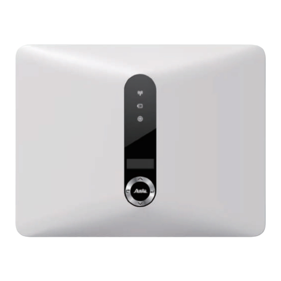
Page 46: Operation Method
Down button: Move cursor to downside or decrease value. ⑧ OK button: Confirm the selection. Breathing light: Normal working status. Rapid flashing: Self-checking status. Status Indicator Red And Green flashing:Update Status. ⑨ Light Slow blinking: Other status. Red light: Fault. Austa High Voltage Hybrid Inverter User Manual... -
Page 47: Lcd Function
8.Operation method 8.2 LCD function Menu structure : Austa High Voltage Hybrid Inverter User Manual... -
Page 48: Lcd Operation
The main screen as below. To access more information, please Press 'OK' to enter the menu. 2. Running Press 'OK' to enter the menu, check the current running status, including Battery, solar, grid, backup. Austa High Voltage Hybrid Inverter User Manual... - Page 49 Backup will only have data when the inverter is working in Backup mode, it will show the real time data of the Backup output. As voltage , current , power, frequency. Press 'ESC' to return to the menu. Austa High Voltage Hybrid Inverter User Manual...
- Page 50 4.1)Date Time Press up or down button to change date and time. Press ‘OK’ to confirm. 4.2)Work Mode Press up or down button to select different work modes. Press ‘OK’ to confirm. Austa High Voltage Hybrid Inverter User Manual...
- Page 51 When the system is connected to a three-phase unbalanced load or a single phase load, customers can disable the balance load. The inverter can detect and identify the three-phase current imbalance in the system through the meter and output unbalanced power to different phases. Austa High Voltage Hybrid Inverter User Manual...
- Page 52 Press the up and down keys to set battery parameters. You can set the maximum and minimum charging and discharging currents of the battery, as well as the maximum and minimum battery capacity limits. Austa High Voltage Hybrid Inverter User Manual...
- Page 53 The inverter can be set to Free Mode or Master Mode. Free Mode: single operation, disabling the Parallel function; Master Mode: the inverter is the Master, and other parallel inverters automatically switch to Slave.Press 'OK' to confirm. Austa High Voltage Hybrid Inverter User Manual...
- Page 54 4.10) Reset Press up or down button to reset energy, reset errors or factory reset. Press ‘OK’ to confirm. 4.11) Language Press up or down button to change language. Press 'OK' to confirm. Austa High Voltage Hybrid Inverter User Manual...
- Page 55 fires caused by arc faults.Press 'OK' to confirm. 5. Device Info This interface shows the information of the inverter, such as series number and software version.Press 'ESC' to return to the menu. Austa High Voltage Hybrid Inverter User Manual...
- Page 56 2. If it frequently occurs, please check whether the grid voltage and frequency are within the allowable range according to local specifications. • If the grid voltage and frequency exceed the allowable range, please contact your local power operator. Austa High Voltage Hybrid Inverter User Manual...
- Page 57 1. Please disconnect the battery, check if the battery connection is correct, reconnect it, and wait for the inverter to return to normal. 2. If it cannot restore to normal, please contact your distributor or after-sales service center. Austa High Voltage Hybrid Inverter User Manual...
- Page 58 EPS OCP The backup side load current is too high. 1. Please disconnect the PV, grid, and battery, then reconnect them, and wait for the inverter to return to normal. Austa High Voltage Hybrid Inverter User Manual...
- Page 59 1. Please disconnect the PV, grid, and battery, then reconnect them, and wait for the inverter to return to normal. 2. If it cannot restore to normal, please contact your distributor or after sales service center. Austa High Voltage Hybrid Inverter User Manual...
- Page 60 1. Please disconnect the PV, grid, and battery, then reconnect them, and wait for the inverter to return to normal. 2. If it cannot restore to normal, please contact your distributor or after sales service center. Austa High Voltage Hybrid Inverter User Manual...
- Page 61 1. Please disconnect the PV, grid, and battery, then reconnect them, and wait for the inverter to return to normal. 2. If it cannot restore to normal, please contact your distributor or after sales service center. Austa High Voltage Hybrid Inverter User Manual...
- Page 62 ·Are the configuration settings correct for your particular installation? ·Are the display panel and the communications cable properly connected and undamaged? Contact Austa Customer Service for further assistance. Please be prepared to describe details of your system installation and provide the model and serial number of the unit.
- Page 63 Scan Here for Austa Solar App Android service tel:400-607-3668 Search "Austa Solar" www.austasolar.net on Google Play and App Store marketing@osdasol.com NINGBO AUSTA SOLAR TECH CO.,LTD...
Need help?
Do you have a question about the AU4KETH and is the answer not in the manual?
Questions and answers