Austa AU Series User Manual
Grid-tied pv inverter
Hide thumbs
Also See for AU Series:
- User manual (50 pages) ,
- User manual (46 pages) ,
- User manual (44 pages)

Related Manuals for Austa AU Series


Summary of Contents for Austa AU Series
- Page 1 AU Series Grid-tied PV Inverter user manual AU 36~50K3P NINGBO AUSTA SOLAR TECH CO.,LTD.
-
Page 3: Table Of Contents
Contents Thank you for choosing AUSTA on-grid PV inverter. In order to ensure your safety and proper use, please Contents read the manual in details before using. Thanks for your cooperation! 1.Overview ..........................1 1.2 Symbols ........................1 2. Description .......................... 2 2.1. -
Page 4: Overview
Contents 1.Overview Overview 1.1 Use of this manual This manual mainly introduces installation, operating and maintenance of inverter and related technical parameters. It is suitable for people who install the inverters and do other related jobs. Readers need to have some knowledge of electric, electrical wiring and mechanics. -
Page 5: Description
Contents 2. Description Description 2.1. Brief Introductions 述 On-grid PV power generation system usually is composed of solar panels, junction box, inverter, ammeter and power grid. The core of the system is PV grid-connected inverter. The sunshine irradiates on the surface of the solar panels, solar panels output DC, converted by inverter, then output AC of the same frequency and phase with the grid, and then feed into the grid. -
Page 6: General Introduction
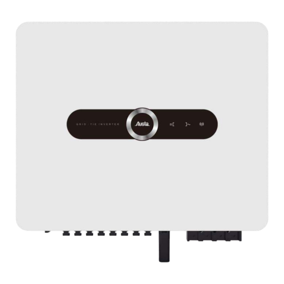
Comprehensive protection, higher reliability. IP66 Outdoor design, suitable for harsh environment . RS485 communication. Optional GPRS/WIFI communication function. 2.2 General introduction Appearance and interface Fig 2-2 Appearance Figure 2-2 shows the product appearance. The picture is for reference only. The external interface is located at the bottom of the product, including PV+ input port, PV - input port,WIFI/GPRS/RS485communication port, AC output port, and DC switch (side). -
Page 7: Inverter Dimension
Name Description Inverter’s DC input port, connect with + PV input port + port of PV arrays Inverter’s DC input port, connect with – PV input port - port of PV arrays Electric cut off between inverter and PV DC switch arrays Connect inverter with PC through this WIFI/GPRS/RS485... -
Page 8: Installation
Contents Installation 3. Installation The following are the installation instructions for this product. Please read these instructions carefully to help you install it correctly. 3.1 Installation Procedure Before installing and operating this product, please strictly abide by the installation sequence and warning symbols. -
Page 9: Installation Preparation
3.2 Installation Preparation Check whether there is damage during transport Although we have carefully tested and inspected the inverter before shipping, there might be damage during transport. So please check them before installation. If there is any damage, please contact the shipping company or directly contact us. -
Page 10: Installation Environment Requirements
3.3 Installation environment requirements The selection of the inverter installation environment plays an important role in its safe operation, performance guarantee, and life guarantee. Here are some basic requirements: The inverter protection level reaches IP65 and can be used for indoor or outdoor installation. ... - Page 11 The inverter should be installed in a location where electrical connections, operation and maintenance are easy. The installation height is preferably such that the LCD screen is at eye level for easy operation of the LCD display panel. ...
- Page 12 The installation environment requires cleanliness. The inverter needs to be installed uprightly, and cannot be placed horizontally or upside down, or tilted. If multiple inverters are installed horizontally side by side, it is best to keep the distance between them at least 50cm, and no objects should be placed on the top of the inverter.
-
Page 13: Mechanical Installation
DANGEROUS Do not place the inverter with inflammable and explosive objects. CAUTION During the operation of the inverter, the temperature is high, please do not touch it! Do not install the inverter in the living area to avoid noise affecting daily life. 3.4 Mechanical Installation 3.4.1 Setting tool ... - Page 14 Fig 3-3 Drawing of fixed plate dimensions If the chassis is to be installed on a concrete wall, drill holes on the wall based on the specifications of the fixing plate, secure the fixing plate to the wall using expansion bolts, and hang the chassis on the fixing plate.
-
Page 15: Electrical Connection
Mounted panel Full thread bolt Metal support fixing plate Accessory Fig 3-6 After hanging the inverter on the fixing plate, use screws to fix the inverter on the fixing plate. Note: In the process of installing the inverter, please pay attention to keep the balance, so as not to hit the wall or other obstacles and damage the machine shell. - Page 16 3.5.2 Wiring requirements After the inverter is firmly installed to the installation site, it can be connected to the PV system. Electrical connections must comply with local laws and regulations. The following are the wiring requirements of the inverter. PV arrays The open circuit voltage of the photovoltaic array should not exceed 1000V.
- Page 17 voltage range of the AC circuit breaker should be greater than 450V, and the current range should be 80-100A (optional according to the model). NOTE Multiple inverters cannot share one circuit breaker. Load cannot be connected between the inverter and the circuit breaker. ...
- Page 18 NOTE:S2 (insulation stripping length) is 2mm-3mm longer than S1 (OT cable terminal crimping area). 3) Remove the insulation layer of the cable through the cable crimping area of the OT terminal, and then crimp the terminal using a hydraulic crimping tool. The crimped portion of the terminal must be insulated with heat shrink or insulating tape.
- Page 19 The inverter has ten PV arrays input regions DC1~DC4. The inverter is configured with an MPPT tracker for each input region. Dangerous High voltage! Electrical shock! Pay attention to safety before electrical connection. Exposure of PV arrays to sunlight will generate dangerous voltage.
- Page 20 1. Remove 7mm of insulation layer from all DC cables. 2. Use crimping pliers to bundle cable ends at wiring terminals. a.female terminal b.male terminal 3. Route the cable through the cable sealing sleeve. 4. Insert the wiring terminal into the insulation sleeve until it is fastened. Gently pull the cable to ensure that it is firmly connected.
- Page 21 7. Off DC switch. 8. Check whether the polarity of the connecting cables of the PV string is correct, and ensure that the open circuit voltage does not exceed the upper limit of the inverter input, 1000V, even at the lowest operating temperature.
- Page 22 8. Repeat the preceding steps to connect other PV arrays. 9. Seal the vacant DC terminal with a terminal cover. ● Grounding WARNING Since the inverter is a transformerless type, it is required that the positive and negative poles of the PV array cannot be grounded, otherwise the inverter will not operate normally. ...
- Page 23 Grounding diagram Secondary protection grounding There is a secondary protection grounding terminal at the bottom of the inverter, which must be grounded. WARNING The grounding connection of the secondary protection grounding terminal cannot replace that of the PE terminal in the AC cable. Ensure that both terminals are reliably grounded. Otherwise, manufacturers and suppliers does not assume any responsibility for possible consequences.
-
Page 24: Monitoring
Figure 5-1 RS485 (standard MODBUS protocol) communication system mode Smart device Figure 4-2 WIFI/GPRS communication system mode After installing the GPRS or Wi-Fi data collector module, you can monitor the operation of the PV system through the AUSTA App program “Ausat Solar”. - Page 25 Collector description ●...
-
Page 26: Austa Pv Wizard App -Solarlnfo
4.2 AUSTA PV Wizard App -Solarlnfo Austa Web/Austa Solar APP is rich in functions, covering the entire life cycle of the power station, it perfectly meets the needs of one-stop management.Austa rovides installers, operation and maintenance providers, and investors with various tools covering the development period, construction period, and operation and maintenance period of the power station.At the same time, it also provides practical... -
Page 27: Trial Run
Contents 5. Trial run Trial run 5.1 Inspection before trial run Trial run is an important step for PV system installation. Proper trial run can prevent fire and other accidents. Correctly connect the PV arrays, inverter and ac power grid according to the installation process described above, and check the content before starting the inverter. -
Page 28: Shut Down
Close the AC side circuit breaker; When the conditions required for normal operation of the machine are met, the inverter will automatically start and connect to the grid for power generation; Grid-connected PV inverter does not need manual control after normal operation, and has automatic shut down and start function after failure. -
Page 29: Shut Down & Dismantle
hut down 6. Shut down & Dismantle Contents & Dismantle 6.1 Stop the inverter It is not necessary to shut down the inverter manually under normal circumstances, but it is necessary to shut down the inverter for maintenance or operation. To disconnect the inverter from the AC/DC power supply, follow the following steps. -
Page 30: Operating
LED indicator and a voice switch are set on the panel, as shown in Figure 7-1. LCD panel LED indicator Voice switch Fig 7-1 AU series LCD control panel LED display status LED indicator Description Grid-connected operation indicator (normal operation,... -
Page 31: Startup Mode
LED indicator Fig 7-2 AU series indicator panel ● LED display status Function Status Description Grid-connected and power generation DC is normal, AC is not powered on Running DC is normal, grid-connected standby Equipment failure DC switch is not powered on... - Page 32 from the startup mode to the running mode, otherwise, it switches to the standby mode. The screen display sequence of the startup mode is shown in Figure 7-3(take AU100K3P as an example). Start Thanks For Using inverter model AU100K3P Inverter SN 17Y1M1Dl POWER 100000W 3~ 400V...
- Page 33 Today's power generation Total power generation 30.5kwh 40.5kwh Fig 7-4 Default interface of running mode In running mode, the screen display content is shown in Table5-3 (take AU60K3P as an example) B phase voltage: 240V IP address B phase current 3: 0.0A C phase voltage: 240V Grid-connected runtime C phase current 3: 0.0A...
- Page 34 NOTE If the DC side is powered off, it will be a new day for the inverter when it is powered on again, and the total energy generated on that day will be recalculated. ● Standby mode The DC start and the grid connection condition is not met is the standby mode. In the standby mode, the inverter continuously detects whether the grid-connected power generation conditions are met.
-
Page 35: Power Generation Process
seconds, the background light will be off, and the LCD screen will return to the default display interface. NOTE The above various LCD display interfaces are switched by tapping the position of the voice-activated switch logo. 7.3 Power generation process The grid-connected power generation process of AU photovoltaic grid-connected inverters is automatic, and the grid-connected process is briefly described (take AU100K3P as an example) 1. -
Page 36: Maintenance
Contents 8.Maintenance Maintenance DANGEROUS Do not open the machine. Users trying to repair the machine by themselves may cause electric shock and fire hazard. 8.1 Maintenance Due to the influence of ambient temperature, humidity, dust and vibration, the internal components of the inverter will age and wear, which will affect the service life of the inverter. - Page 37 Failure solution 1. Disconnect AC side circuit breaker. 2. Disconnect DC side circuit breaker. LED indicator and LCD 3. Check the input voltage of the PV arrays (whether it is lower screen do not light up than 250V). 4.If the above conditions are met, check the circuit breaker. 1.
- Page 38 duct is unblocked. 5. Whether the output power exceeds the rated value. 1. Disconnect AC side circuit breaker. 2. Disconnect DC side circuit breaker. Grounding fault 3.Check whether the ground resistance of each group of PV arrays is greater than 2MΩ. Table 8-1 troubleshooting If the fault cannot be solved or your problem is not mentioned in the above table, please contact supplier.
-
Page 39: Specification
Contents 9. Specification Specification 9.1 Specification AU36K3P AU40K3P AU50K3P Technical Data DC Input Data Max. DC input power (KW) Max. DC input voltage(VDC) 1100 Max. DC input current(A) 30A*3 30A*4 36A/36A/20A/20A MPPT voltage range(VDC) 250~1000 Recommended working voltage(VDC) MPPT number Max. -
Page 40: Quality Guarantee
The warranty period of this product shall be subject to the contract. condition AUSTA will repair or replace the faulty products free of charge during the warranty period. Unqualified products after replacement shall be returned to AUSTA. ... - Page 41 Thank you for taking time to share your feedback. Your comments and suggestions will help us to serve you better. Please send fax or e-mail your feedback, we will respond you within 24 hours. Contact Information NINGBO AUSTA SOLAR TECH CO.,LTD. Tel: +86 574 89137130 Email: marketing@osdasol.com Web:www.austasolar.net Add: 1-1 NO.136 Haichuan Road Jiangbei...
- Page 42 NINGBO AUSTA SOLAR TECH CO.,LTD. Tel: +86 574 89137130 Email: marketing@osdasol.com Web:www.austasolar.net Add: 1-1 NO.136 Haichuan Road Jiangbei District Ningbo Zhejiang P.R. China...
Need help?
Do you have a question about the AU Series and is the answer not in the manual?
Questions and answers