Table of Contents
Advertisement
Quick Links
Advertisement
Table of Contents

Related Manuals for Lutz Jesco TOPAX L CH/CD


Summary of Contents for Lutz Jesco TOPAX L CH/CD
- Page 1 A measured step forward TOPAX L - O&M Manual...
-
Page 2: Table Of Contents
Table of Contents 1 Safety ..........................3 1.1 Electrical Safety ........................3 1.2 Operating Environment ......................3 2 Intended Use ........................4 2.1 Notes on Product Warranty ....................... 4 2.2 Intended Purpose ........................4 2.3 Foreseeable Misuse ......................... 4 2.3.1 Incorrect Assembly ....................4 2.3.2 Incorrect Start-Up ..................... -
Page 3: Safety
1 Safety 1.1 Electrical Safety All of the control unit’s connections are isolat- ed from the grounding system (non-insulated grounding conductor). Do not connect any of these connections to the grounding connector. To guarantee maximum conditions of safety for the operator, it is recommended to follow all of the instructions listed in this guide: ■... -
Page 4: Intended Use
2 Intended Use 2.1 Notes on Product Warranty Any non-designated use of the device can impair its function and the protection provided. This leads to invalidation of any warranty claims! Please note that liability is on the side of the user in the following cases: ■... -
Page 5: Incorrect Maintenance
2.3.4 Incorrect Maintenance ■ Carrying out maintenance during ongoing operation ■ No adequate or regular inspection of correct functioning ■ No replacement of damaged parts or cables ■ No securing against reactivation during maintenance work ■ Using the wrong spare parts 3 Product Description 3.1 Scope of Delivery The following items are part of the scope of delivery:... -
Page 6: Control Panel
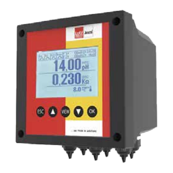
3.4 Control Panel Fig. 1: Control Panel Item Description LCD display Cancel action or exit menu Move up or increase the value (▲) Select view Move down or decrease the value (▼) Confirm action or open the menu Tab. 1: Legend for the Control Panel 3.5 Standard View The standard view of the device is split into two sections: Fig. -
Page 7: Technical Data
4 Technical Data 4.1 Mechanical Specifications Dimensions of housing (W x H x D) 6 x 6 x 5 in Front frame (W x H) 6 x 6 in Weight 2.31 lbs. (1.05 kg) Material ABS/polycarbonate Protection IP65 Relative humidity 0 to 100 % condensing 4.2 Environmental Conditions Storage temperature... - Page 8 SSR Outputs (Solid State Relays) SSR1 and SSR2 2-SPST 60 V, max 100 mA, bidirectional, NPN, PNP Resistance in ON state max. 5 Ω Leakage current in OFF state max. 1 uA SSR1 and SSR2 configuration Pulse output Frequency range 0 –...
-
Page 9: Dimensions
5 Dimensions All dimensions in inches. 5.1 Outer Dimensions Einkanalregler TOPAX L - Maßbild weiß gefärbt 4.80” 5.66” 40700001_2 Fig. 3: Outer Dimensions 5.2 Drillhole Dimensions 3.14” Ø 0.23” Fig. 4: Drillhole Dimensions P h o n e : ( 5 8 5 ) 4 2 6 - 0 9 9 0 www.lutzjescoamerica.com Fax:... -
Page 10: Installation
6 Installation 6.1 Principles Make sure that the installation location complies with the following requirements: ■ The display is easily accessible and is visible. ■ Leave enough space for installing cables underneath the device. You must be able to install cables without kinking or damaging them. -
Page 11: Rc Protection For Relays
DANGER Mortal danger from electric shock! Improperly installed or damaged components in the electronics installation can cause injury. The electrical line must be equipped with an appropriate circuit breaker, in compliance with the proper installation standards. The power supply and the quality of the grounding connector must be checked to avoid electrical interference. 6.4 RC Protection for Relays When connecting to the relays, note that inductive loads must be suppressed. - Page 12 Terminal Terminal Designation Description L/ + Power Supply N/ - Relay 1 contact RL 1 Relay 2 contact RL 2 Relay 3 contact RL 3 Relay 4 contact RL 4 11 - 12 Not used Not used Communication port RS485 MODBUS RTU/ASCII RS485 RS485 GND pin is isolated from GND (pin 20) RS485 GND...
-
Page 13: Connection Examples
6.6 Connection Examples 6.6.1 Power Supply 24 – 48 V DC or 100 – 240 V AC; check the product label Observe the polarity. Observe the maximum power consumption (see „Electrical Specifications“ on page 7). Power supply Power supply 100 –... -
Page 14: Relay Outputs 1, 2, 3 And 4
6.6.3 Relay Outputs 1, 2, 3 and 4 Maximum load 5 A resistive. Power supply Power supply 100 – 240 V AC 100 – 240 V AC Dosing pump Alarm Dosing pump Alarm Fig. 8: Connection Example for Relay Outputs 1, 2, 3 and 4 6.6.4 Current Outputs mA 1 and 2 ... -
Page 15: Reed Sensor Input
6.6.6 Reed Sensor Input Input for dry contact or semi-conductor (open collector) 5 V DC, max. 6 mA. Observe the maximum cable length (65 ft.) for the reed sensor. Reed sensor Reed Fig. 10: Connection Example for Reed Sensor 6.6.7 Input for Temperature Measurement ...
Need help?
Do you have a question about the Jesco TOPAX L CH/CD and is the answer not in the manual?
Questions and answers