Sign In
Upload
Download
Table of Contents
Contents
Add to my manuals
Delete from my manuals
Share
URL of this page:
HTML Link:
Bookmark this page
Add
Manual will be automatically added to "My Manuals"
Print this page
×
Bookmark added
×
Added to my manuals
Manuals
Brands
Lutz Manuals
Measuring Instruments
TR3-PP
Translation of the original instructions
Lutz TR3-PP Translation Of The Original Instructions
Flow meter
Hide thumbs
1
Table Of Contents
2
3
4
5
6
7
8
9
10
11
12
13
14
15
16
17
18
19
20
21
22
23
24
25
26
27
28
page
of
28
Go
/
28
Contents
Table of Contents
Bookmarks
Table of Contents
Table of Contents
1 Concerning this Manual
Terms
Target Groups
Associated Applicable Documents
Warnings and Symbols
Latest State
Copyright
2 Safety
General Safety Information
Proper Use
Technical Data
Liability
Prevention of Obvious Misapplication (Examples)
3 Configuration
Identification
Display
Keypad
Battery
4 Transport and Storage
Transport
Storage
5 Assembly
General
Assembly with Drum Pump Connection G1
Assembly with Drum Pump Connection G1 1/4
Assembly at Nozzle PP/PVDF with Standard Hose Connector and Hose Connector Twistable
Rotating the Display
6 Operation
Description of Display
Dispensation Mode
Dispensation Active
No Active Dispensation
7 Programming the Meter
Change over into Programming Mode
Setting the Unit of Measurement
Setting the Meter Type
Setting the Calibration Factor
Calibration
Calibration with Measuring Vessel
8 Maintenance
Cleaning The Flow Meter
Changing the Batteries
9 Error Messages - What Do I Do When
10 Waste Disposal
Return of Batteries
Spare Part List
Declaration of Conformity
Advertisement
Quick Links
Download this manual
en
Translation of the original instructions
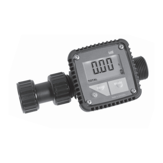
FLOW METER
Type
TR3-PP
TR3-PVDF
Read this operating instructions before start up!
To be retained for future reference.
Table of
Contents
Previous
Page
Next
Page
1
2
3
4
5
Advertisement
Table of Contents
Need help?
Do you have a question about the TR3-PP and is the answer not in the manual?
Ask a question
Questions and answers
Related Manuals for Lutz TR3-PP
Measuring Instruments Lutz TR90-PP Operating Instructions Manual
Flow meter (220 pages)
Measuring Instruments Lutz TR90-PP Operating Instructions Manual
(24 pages)
Measuring Instruments Lutz TR3-PVDF Translation Of The Original Instructions
Flow meter (28 pages)
Measuring Instruments Lutz ST Operating Instructions Manual
Modular flow meter system ts with and without volume preselection (72 pages)
Measuring Instruments Lutz ST10 Translation Of The Original Instructions
Basic (56 pages)
Measuring Instruments Lutz Jesco TOPAX L CH/CD O & M Manual
(16 pages)
Measuring Instruments Lutz SafetyBox Translation Of The Original Instructions
Monitoring module (16 pages)
Measuring Instruments Lutz RM10 Manual
Relay module / power supply unit (36 pages)
Measuring Instruments Lutz MDO2 Translation Of The Original Instructions
(36 pages)
Measuring Instruments LUTZ MDO2 Original Instructions Manual
(36 pages)
This manual is also suitable for:
Tr3-pvdf
Table of Contents
Print
Rename the bookmark
Delete bookmark?
Delete from my manuals?
Login
Sign In
OR
Sign in with Facebook
Sign in with Google
Upload manual
Upload from disk
Upload from URL


Need help?
Do you have a question about the TR3-PP and is the answer not in the manual?
Questions and answers