Table of Contents
Advertisement
Quick Links
—
A B B M E A S U R E M E N T & A N A LY T I C S | o p E R AT I N g I N S T R U C T I o N
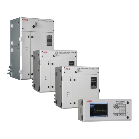
PGC5000 Series Gen 1
Process gas chromatographs
Measurement made easy
Further information
Additional documentation on the pgC5000 process
gas chromatograph is available for download at
www.abb.com/analytical.
Alternatively simply scan this code.
Advertisement
Table of Contents

Related Manuals for ABB PGC5000 Gen1 Series


Summary of Contents for ABB PGC5000 Gen1 Series
- Page 1 A B B M E A S U R E M E N T & A N A LY T I C S | o p E R AT I N g I N S T R U C T I o N PGC5000 Series Gen 1 Process gas chromatographs Measurement made easy Further information Additional documentation on the pgC5000 process gas chromatograph is available for download at www.abb.com/analytical. Alternatively simply scan this code.
- Page 2 ABB Inc. and its affiliates are not liable for damages and/or losses related to such security breaches, any unauthorized access, interference, intrusion, leakage and/or theft of data or information.
-
Page 3: Table Of Contents
PGC5000 PGC5000 Series Operating Instructions Contents Contents Glossary .............. 6 Starting the analyzer ..........20 5.4.1 Leak check oven ........21 Safety and symbols ..........7 5.4.2 Leak check carrier gas supply lines ..21 Calibrating the analyzer ......... 21 Introduction ............ - Page 4 PGC5000 PGC5000 Series Operating Instructions Contents Subscriber tab ............60 7.8.4 MODBUS slave communication ....83 6.7.1 Creating a new subscriber ......61 7.8.5 Client configurator ........84 6.7.2 Adding an existing device ......62 7.8.6 OPC communication ......... 86 6.7.3 Subscriber events ........
- Page 5 PGC5000 PGC5000 Series Operating Instructions Contents 9.4.30 INJECT TIME function ......106 9.4.58 SCHEDULE NAME function ..... 110 9.4.31 INTEGER TYPE conversion routine ..106 9.4.59 SCHEDULE RUN function ......110 9.4.32 LENGTH function ........106 9.4.60 SCHEDULE STOP command ....110 9.4.33 LOGARITHM BASE TEN function ....
-
Page 6: Glossary
PGC5000 PGC5000 Series Operating Instructions 1 Glossary 1 Glossary Access Control List ANSI American National Standards Institute Absence of Condtion Controller Area Network Config Configuration Digital Signal Processing Digital Temperature Controller Electromagnetic Compatibility Electronic Pressure Controller Flame Ionization Detector Flame Photometric Detector File Transfer Protocol Input/Output Internet Protocol... -
Page 7: Safety And Symbols
PGC5000 PGC5000 Series Operating Instructions 2 Safety and symbols 2 Safety and symbols The following symbols are used in this manual to alert the user to possible hazards and to provide additional information. Indicates that referenced items are Indicates that the referred item can be hot and should not be touched without susceptible to Electrostatic Discharge care. -
Page 8: Introduction
PGC5000 PGC5000 Series Operating Instructions 3 Introduction 3 Introduction 3.1 General The PGC5000 Series Process Gas Chromatograph (analyzer) separates and measures the individual components of gas or liquid samples. It automatically samples and analyzes process streams, using the analyzer’s Master Controller to control analytical functions. -
Page 9: Liquid Version
PGC5000 PGC5000 Series Operating Instructions 3 Introduction 3.4.1 Liquid version The liquid version incorporates a liquid sample valve (LSV) as the input to the analysis. The duration of an analysis depends on the application and consists of the following: The liquid sample valve injects a fixed volume of sample into a vaporizing chamber. •... -
Page 10: Installation
PGC5000 PGC5000 Series Operating Instructions 4 Installation 4 Installation 4.1 Safety considerations Before starting to install the analyzer, read the safety information below. Before beginning installation, repair, or maintenance on the analyzer, contact the local Safety Department to ensure that all safety guidelines, regulations and procedures are followed. This includes obtaining the proper work permits. -
Page 11: Ovens
PGC5000 PGC5000 Series Operating Instructions 4 Installation Not intended for below surface mining applications • • Free from dust and static electricity • Space of at least 152 mm (6 inches) to the right side of the Master Controller, if purge equipped •... -
Page 12: Plumbing Installation
PGC5000 PGC5000 Series Operating Instructions 4 Installation 4.3.2 Plumbing installation All plumbing connections enter at the right side of the Oven and Master Controller cabinets. Be careful to avoid damaging fittings and to ensure tight connections. Refer to the Data Package for specific plumbing information. For brass and stainless steel pipe fittings, wrap the threads with PTFE tape or a suitable thread sealant. -
Page 13: Burner Fuel
PGC5000 PGC5000 Series Operating Instructions 4 Installation Carrier gas dryer is recommended for capillary column applications. 4.5.4 Burner fuel The burner fuel, when used, is connected to the fitting marked Burner Fuel. 4.5.5 Burner air The burner air, when used, is connected to the fitting marked Burner Air. 4.5.6 Sample The methods used for transporting the sample from the process stream to the analyzer, or from the calibration sample to the analyzer, are critical to the operation of the analyzer. -
Page 14: Electrical
PGC5000 PGC5000 Series Operating Instructions 4 Installation To ensure the integrity of the components within the Liquid Sample Valve, use the tools in LSV Tool Kit 791K009-1 when assembling of disassembling the LSV. 4.6 Electrical The analyzer must be installed according to all applicable codes. If it is in a hazardous area, the wiring method must conform to the applicable requirements. -
Page 15: Purge Air Alarm
PGC5000 PGC5000 Series Operating Instructions 4 Installation Sharp bends in a fiber optic cable can cause signal attenuation or the optical fiber to break. The ST connectors have a bayonet mount and a long cylindrical 2.5 mm ceramic or polymer ferrule to hold the fiber. They are spring-loaded and keyed with slots and alignment nubs. -
Page 16: Start-Up
PGC5000 PGC5000 Series Operating Instructions 5 Start-up 5 Start-up 5.1 Introduction The analyzer operates by separating the oven and controller functions. The application configured at the factory establishes the operational baseline and expected results as requested by the customer. The analyzer can be controlled at either the Local User Interface (LUI) or the Remote Client. -
Page 17: Action Items
PGC5000 PGC5000 Series Operating Instructions 5 Start-up 5.2.2 Action icons Action icons are small pictures that represent action commands. In this manual the text will utilize the meaning/function shown below in referring to the icons. Figure 5.3 shows the action icons and provides a brief description of each one. Icon Meaning/Function Icon... -
Page 18: System Information Bar
PGC5000 PGC5000 Series Operating Instructions 5 Start-up 5.2.4 System information bar The System Information Bar (see Figure 5.5), which is located along the bottom of the screen, gives a variety of information as noted in the following list. Fig. 5.5. System Information Bar System Status Indicator –... -
Page 19: Keypad
PGC5000 PGC5000 Series Operating Instructions 5 Start-up 5.2.6 Keypad The keypad is used for numerical input and cursor movement (see Figure 5.6). From this keypad, which is located to the right of the display, navigation is accomplished by either pressing symbol keys or using the touch pad. The function of the keys is explained below. -
Page 20: Oven Controls And Indicators
PGC5000 PGC5000 Series Operating Instructions 5 Start-up 5.3 Oven controls and indicators Figure 5.8 shows the controls and indicators for a typical oven. Both the Class B Oven and the Class C Oven have the same controls and indicators. Gauges Regulators Indicator Lights... -
Page 21: Leak Check Oven
PGC5000 PGC5000 Series Operating Instructions 5 Start-up 5.4.1 Leak check oven This is recommended at startup or if an internal carrier gas leak is suspected. Perform a simple leak check on the oven section as follows (see Figure 5.9): Fig. 5.9. Leak Check Oven Example Plug all oven carrier gas vents as applicable: backflush vent(s), selector vent, detector vent(s) and splitter vent. -
Page 22: Validation Run
PGC5000 PGC5000 Series Operating Instructions 5 Start-up Navigate to the Setup tab (see Figure 5.10). Fig. 5.10. Setup Tab, Showing Calibration Concentration Select the Components button from the Function Selectors list. Verify that the Config sub-tab at the bottom of the screen is selected. Select the component to calibrate from the COMPONENTS NAME drop down menu. - Page 23 PGC5000 PGC5000 Series Operating Instructions 5 Start-up The Network Connect button is located in the system information bar at the bottom left of the display, showing two boxes connected by a green line (see Figure 5.11). If you launch the Remote Client from STAR Client, the IP Address will appear in the box next to the Network Connect button.
-
Page 24: Using The Access Control List
PGC5000 PGC5000 Series Operating Instructions 5 Start-up If you click on the Network Connect button again, you will get the IP Address Dialog Box, which will allow you to enter the desired IP address (see Figure 5.13). After you enter the desired IP Address, click on Accept to save the entry or click on Abort to retain the original settings. -
Page 25: Subscriber List
PGC5000 PGC5000 Series Operating Instructions 5 Start-up All Supervisors have the ability to determine each user's required access level and enter the information into the ACL. If the Information Bar states ‘Login access Unsecured,’ all users have full access (Supervisor level). 5.8.3 Subscriber list The Subscriber Tab allows analysis results, status change and analyzer events reporting to the Reporter, the OPC, and the STAR Server. -
Page 26: Operation
PGC5000 PGC5000 Series Operating Instructions 6 Operation 6 Operation 6.1 Introduction The PGC5000 analyzer operates from a series of tabs at the top of the screen. All functions of the analyzer are accessed from these tabs and their sub-tabs, which are located at the bottom of the screen. 6.2 Home tab The Home tab is the Master Controller’s default screen displayed when the system starts. -
Page 27: Status Sub-Tab
PGC5000 PGC5000 Series Operating Instructions 6 Operation To zoom an area, use the cursor to select a point on the chart as a starting point (see Figure 6.2). Hold the mouse button down and drag the box over the desired viewing area. Release the mouse button to complete the zoom. To return to the default view, select the crossed arrow button, in the lower right corner of the screen. -
Page 28: Report Sub-Tab
PGC5000 PGC5000 Series Operating Instructions 6 Operation 6.2.3 Report sub-tab The Home>Report sub-tab displays the analysis information (see Figure 6.4). Fig. 6.4. Home>Report Sub-tab Analysis Buttons– Displays the indicator level and analysis progress for all active analyses. The “Idle Stream” is included for review of analyses not currently running. - Page 29 PGC5000 PGC5000 Series Operating Instructions 6 Operation The standard report (see Figure 6.5) displays inject time, sample stream, analysis name, report type, detector, component Name / Retention Time / Concentration and validity of the component. Fig. 6.5. Standard Report Format The raw data report (see Figure 6.6) displays the actual value of software determined points on the chromatogram, in addition to the information displayed in the standard report format.
-
Page 30: Overlay Sub-Tab
PGC5000 PGC5000 Series Operating Instructions 6 Operation Select report inject time to view. Reports are saved by inject time in the following format: TYPE/Year/Month/Day/Hour/Minute/Second (STD201507301629). View the data (see Figure 6.6). 6.2.4 Overlay sub-tab The analyzer supports the overlaying of stored chromatograms on the screen for use as a reference. A maximum of two stored chromatograms can be viewed simultaneously on the Chart Sub-tab, plus the active stream. -
Page 31: Status Tab
PGC5000 PGC5000 Series Operating Instructions 6 Operation Overlay 1 (top) displays in green; Overlay 2 (bottom) in red. To turn off the overlay display, unmark the Active box on the Overlay Sub-tab. The Master Controller stores analysis data continuously for a maximum of seven days. Report files are overwritten after seven days or when the storage media is filled. -
Page 32: User Configurable Scopes
PGC5000 PGC5000 Series Operating Instructions 6 Operation Page Up/Down – Line Up/Down – Select buttons to move vertically through indicators. Depending on location or size of list, movement arrows may not be shown. (Example: top of list, page up arrows will not be shown.) Headings, from left to right of screen, are described in Figure 6.10. -
Page 33: Configuring Indicators
PGC5000 PGC5000 Series Operating Instructions 6 Operation Oven Sub-scope– Any active, triggered, alarm-level indicator activates the common malfunction relay contact closure for the associated oven. Stream – Any active, triggered, alarm-level indicator invalidates the analysis data reported to all subscribers for that stream. (This may span multiple analyses.) It also sets the Is Valid indicator. -
Page 34: Maintenance Mode Icon
PGC5000 PGC5000 Series Operating Instructions 6 Operation 6.4.1 Maintenance mode icon The Maintenance Mode icon sets the selected schedule's maintenance indicator. If desired, the maintenance mode indicator may be placed in a scope at a level that invalidates reported data. 6.4.2 Power failure recovery icon This software offers automatic, independent system control for planned or inadvertent power failure. -
Page 35: Multiple Oven & Schedule Relationship
PGC5000 PGC5000 Series Operating Instructions 6 Operation Figure 6.12 illustrates the determination of the schedule recovery modes. Fig. 6.12. Power Recovery Options 6.4.3 Multiple oven and schedule relationship Each schedule can use the oven hardware in more than one oven, allowing more than one oven association with a single schedule. -
Page 36: Queue Sub-Tab
PGC5000 PGC5000 Series Operating Instructions 6 Operation In each example, an X represents an offline oven (the offline condition may be initiated for maintenance, power failure or possible associated equipment failure). In Example A, Oven 4 has gone offline. Only schedules 1 and 4 are impacted. In Example B, Oven 2 is offline and impacts only schedules 1 and 2. -
Page 37: Step Sub-Tab
PGC5000 PGC5000 Series Operating Instructions 6 Operation 6.4.5 Step sub-tab Figure 6.16 shows the Step sub-tab display. It allows the user to add steps to a schedule. Fig. 6.16. Schedule>Step Display Schedule Select – Select schedule to show detail. Add Action Icon – Select the Add icon to add an analysis. Analysis Control Area –... -
Page 38: Demand Sub-Tab
PGC5000 PGC5000 Series Operating Instructions 6 Operation The TOD sub-tab sets scheduled validations, calibrations and stream analyses. The steps to add a TOD analysis are: Select the Add button at the top of the sub-tab display and a selection list appears. Select a stream from the list and press the Next button to continue. -
Page 39: Chart Sub-Tab
PGC5000 PGC5000 Series Operating Instructions 6 Operation 6.5.1 Chart sub-tab The Analysis>Chart sub-tab is used to display and edit analyses graphically (see Figure 6.19). The parallel lines with the colored symbols at the bottom of the chart screen graphically identify analysis objects. Fig. -
Page 40: Tabular Editor Sub-Tab
PGC5000 PGC5000 Series Operating Instructions 6 Operation Figure 6.20 shows the corresponding placement of symbols on the Chart sub-tab in relation to the numbers entered from the Tabular Editor sub-tab. Placement of the symbols can be edited from either sub-tab. TIME OFFSET CREST BEGI N... -
Page 41: New Analysis
PGC5000 PGC5000 Series Operating Instructions 6 Operation percentage of the sum of the areas of all the peaks. Normalization applies to analyses where the quantitative response of the detector is the same for all the eluted components. By default, the PGC5000 does not normalize component results. However, there is an option in the Analysis tab to normalize the Analysis results. -
Page 42: Analysis Error Messages
PGC5000 PGC5000 Series Operating Instructions 6 Operation • Analysis - Consists of one or more methods (maximum of one per oven), which produces a measurable, displayable chromatogram. Sequence - Consists of timed valve functions (On or Off), TCFs and sample injections. A sequence is under a method. •... - Page 43 PGC5000 PGC5000 Series Operating Instructions 6 Operation Message Issue / Fix TCF is outside Method A TCF non-End of Analysis script precedes the start of the first Method defined in the Analysis Component TCF - Begin crest time > 0 A Component TCF has a ‘Crest Begin' time offset that is less than zero Component TCF - Begin time >= End time A Component TCF cannot have a 'Crest Begin’...
-
Page 44: Loading An Analysis From The Library
PGC5000 PGC5000 Series Operating Instructions 6 Operation Message Issue / Fix StreamStep TCF starts at time < 1 second A 'Stream Step' TCF cannot start at a time of less than one second into the CycleTime (MaxTcfEndTime = [Secs]) > (CycleTime= Some TCF in the Method exceeded this containing Method's CycleTime [Secs]) Not all TCFs have a valid start time... -
Page 45: Running An Existing Schedule
PGC5000 PGC5000 Series Operating Instructions 6 Operation 6.5.7 Running an existing schedule Please refer to the Schedule Tab for running a schedule. 6.5.8 Stopping or pausing schedules Refer to the Schedule Tab for information concerning stopping or pausing a schedule. 6.5.9 Overlay sub-tab The Analysis>Overlay function works exactly the same as the Home>Overlay screen. -
Page 46: Setup Tab
PGC5000 PGC5000 Series Operating Instructions 6 Operation Go to the Report sub-tab and note the data. Go to the Chart sub-tab and adjust any of the integration parameters (retention time, baseline, etc.). Return to the Overlay sub-tab and select the Reprocessing Action icon again. Return to the Report sub-tab and note changes in the data displayed. -
Page 47: System Restore And Recovery
PGC5000 PGC5000 Series Operating Instructions 6 Operation 6.6.2 System restore and recovery The analyzer has several recovery options and file transfer function available as shown in Figure 6.27. These options allow restore point creation and/or chromatogram data file copy (for offline use) or deletion, as explained below. Factory Restore Access Control List... -
Page 48: System Error Messages
Host Name in the configuration does not match the Host Name on the Master Controller: Call ABB support Invalid Configuration Model Manager Task not There is an error in one of the configuration files: Call ABB started support Restore Point Configuration Capture Complete... -
Page 49: Components
PGC5000 PGC5000 Series Operating Instructions 6 Operation Message Meaning / Issue / Fix USB Recovery Drive Creation Complete Recovery data has been saved to the USB flash drive USB Recovery Drive No USB Drive Found No USB flash drive found. Insert USB flash drive in Master Controller SBC PCB User Configuration Restore No Restore Point Found USB Flash drive has no Restore point files. -
Page 50: Streams
PGC5000 PGC5000 Series Operating Instructions 6 Operation HIGH-HIGH – Sets the high-high indicator concentration limit The Status sub-tab displays component’s associated indicators, their state and allows reset. (The component indicators must be marked active on the Status Tab to see state color.) 6.6.5 Streams The Streams button in the Function Select list displays all streams configured for the analyzer (see Figure 6.30). -
Page 51: Master Controller
PGC5000 PGC5000 Series Operating Instructions 6 Operation 6.6.6 Master controller Selecting the Master Controller button in the Function Select list displays the Config and Status sub-tabs and all associated cards and peripherals (see Figure 6.31). Fig 6.31. Master Controller Configuration The associated items are shown in an indented list under the selected button in the Function Select list. - Page 52 Navigate to the Setup>Config Sub-tab. Select Network Adapters from the Function Select list. Since the HOST NAME and STAR Network Port are configured at the ABB factory, they should not be changed. Enter the Primary NIC and Secondary NIC addresses.
-
Page 53: Oven Configuration
PGC5000 PGC5000 Series Operating Instructions 6 Operation Network Routing: The PGC5000 series has the ability to route through different networks using routing tables. Up to four routes can be configured per network interface. Configure the routing tables by selecting the Routing Table Configuration icon. The popup entry form allows the creation of a routing table for each network. -
Page 54: Oven Buttons
PGC5000 PGC5000 Series Operating Instructions 6 Operation Since there may be more than one oven, the Oven button in the Function Select list may indicate the oven number (i.e., Oven 1, Oven 2). The Oven button displays information about the oven selected and lists the oven ancillary items including the Power Supply, Purge Control, Digital Temperature Controls, Electronic Pressure Controller and the Detector Amplifier (see Figure 6.35). - Page 55 PGC5000 PGC5000 Series Operating Instructions 6 Operation Configuring digital inputs steps (see Figure 6.36): Identify the digital input to configure. Select DTC>Digital Inputs from the Function Select list. Either enter text or select an option from dropdown list. Fig. 6.36. Setup Digital Inputs Digital Input Status: The digital input status sub-tab displays the current state of the inputs (see Figure 6.37).
- Page 56 PGC5000 PGC5000 Series Operating Instructions 6 Operation Oven>DTC 1>Pneumatic Actuator>Config displays the actuator part number (see Figure 6.38). All factory configured valve outputs are displayed below the pneumatic actuator button, with the color coded indicators displaying the state of all regulated and unregulated valves.
-
Page 57: Isothermal Oven
PGC5000 PGC5000 Series Operating Instructions 6 Operation Oven>DTC 1>Pneumatic Actuator/Valve Driver#>Valve(#)>Config displays the valve information related to the valve driver with the same number. For internal valves (see Figure 6.40), this screen provides the specific information on the valve type and the configuration of the analyzer. -
Page 58: Electronic Pressure Control
PGC5000 PGC5000 Series Operating Instructions 6 Operation To adjust the oven temperature: Select the Oven>DTC 1>Iso Oven>Config sub-tab. On the Isothermal Oven screen, insert Setpoint and/or Limit values as appropriate. Check and/or adjust the temperature configuration as necessary. The Schedule will not start until the Low Temp Limit for the Isothermal oven has been met. The Oven>DTC 1>Iso Oven>Status sub-tab displays the state and date/time of all active indicators in the DTC zone group. -
Page 59: Detector Amplifier
PGC5000 PGC5000 Series Operating Instructions 6 Operation Zone # Configuration: This sub-tab displays the Zone ID, Name, Actual Pressure, Ramp Rate and Setpoint (see Figure 6.44). Enter the NAME, SETPOINT, LOW LIMIT, HIGH LIMIT, ZONE TYPE and mark ZONE ACTIVE to activate the zone from this screen. Fig. -
Page 60: Subscriber Tab
PGC5000 PGC5000 Series Operating Instructions 6 Operation The Oven> DetAmp> TCD> Configuration sub-tab displays the Serial, Part, and Channel number (see Figure 6.46). It also displays the Filament Information, Gain factor and Output Voltage. A manual AUTOZERO button is provided. You can also edit the input and output fields for easy reference from this screen. -
Page 61: Creating A New Subscriber
Add New – Adds new subscriber. Name and IP addresses will have to be manually entered. NAME Configurable name of the reporting device. TYPE The device type of receiver: OPC (ABB’s OPC Server), RD (Report Device) or STR (STAR Server). IP ADDRESS Primary IP network address of the report device. SECONDARY Secondary IP network address of the report device. -
Page 62: Adding An Existing Device
PGC5000 PGC5000 Series Operating Instructions 6 Operation 6.7.2 Adding an existing device To add an existing device to the subscriber list: Select the Add Icon to open the device setup box. Select the Device from the list. Select the appropriate device type from the drop down list and press the Next button to continue. Press the Accept button to accept the configuration and add it to the list, or press the Abort button to cancel the add operation. -
Page 63: Failover Operation
PGC5000 PGC5000 Series Operating Instructions 6 Operation Event Trigger/Origination Point Associated Indicator Maintenance Completed: Schedule Maintenance Ends: Maintenance Maintenance <ScheduleName> Button deactivated Step Table Changed An entry in a Schedule Step Table has been Report Only altered Time of Day (TOD) Table Altered An entry in a Schedule Time Of Day Table has Report Only been altered... - Page 64 PGC5000 PGC5000 Series Operating Instructions 6 Operation Stream level data tags can also be viewed/tested by selecting the Streams tab at top of screen (see Figure 6.52). Users can check/test the Stream level data tags by selecting which Streams tags they want to view from the drop down selection box below Stream tab at top of screen.
-
Page 65: Program Tab
PGC5000 PGC5000 Series Operating Instructions 6 Operation 6.8 Program tab The Program Tab gives the operator a means for programmatic control and calculations in addition to the built-in capabilities. This provides the necessary support to customize operation of the analyzer to support unique requirements. Section 9 provides detailed information on the scripting process. -
Page 66: Technical Description
PGC5000 PGC5000 Series Operating Instructions 7 Technical description 7 Technical description 7.1 Functional description Figure 7.1 shows a typical analytical flow system, using the flame ionization detector for illustration. Connections at the right side of the analyzer cabinet provide all gas and air inputs. Sliding plate valves, liquid sample valves, or a combination of both, provide control and measurement of the sample. -
Page 67: Thermal Conductivity Detector
PGC5000 PGC5000 Series Operating Instructions 7 Technical description The FID Amplifier Assembly provides ignition control for the FID cell and amplification of the detector cell output signal prior to routing the signal to the control section for signal processing. It consists of a power supply, igniter assembly, electrometer amplifier, and associated circuitry. -
Page 68: Optional Discharge Ionization Detector
The Discharge Ionization Detector (DID) consists of a detector unit and a power supply (see Figure 7.2). Detector Unit Power Supply Fig. 7.2. Discharge Ionization Detector The DID is used in the ABB analytical process gas chromatograph for parts-per-billion (ppb) and parts-per-million (ppm) measurements of the following: Impurities in high purity gases •... -
Page 69: Peak Detection
7.3.2 Min-max method overview The ABB Min-Max method of chromatographic peak detection provides a higher level of accuracy than the classic method. The ultimate goal of the PGC is to provide the end user with a repeatable and accurate determination of component concentrations. - Page 70 PGC5000 PGC5000 Series Operating Instructions 7 Technical description minimum point within the window. The SI and EI determine the beginning and end of peak area integration, while SB and EB determine the beginning and end of baseline correction. Figure 7.5 is an example of the integration and the baseline correction windows for a peak doublet with a valley between, where only one of the peaks is integrated.
-
Page 71: Baseline Correction, Peak Lumping
PGC5000 PGC5000 Series Operating Instructions 7 Technical description 7.3.4 Baseline correction, peak lumping The Min-Max method completely defines the peak but requires careful placement of the windows to cover all situations. The projection of a peak is used when either the SB or the EB are offset from each other, or when no stable place can be found for one of them. -
Page 72: Component Detection (Ez Peak)
PGC5000 PGC5000 Series Operating Instructions 7 Technical description 7.4 Component detection (EZ peak) The analyzer currently uses min-max peak detection as described in this section. After Version V3.0.2.1 of the PGC5000 analyzer, an EZ Peak feature is included in the software. It allows users to define a peak area by entering only two variables: Component Retention Time (RT) and a Threshold measurement. -
Page 73: Single Peak Integration Range
PGC5000 PGC5000 Series Operating Instructions 7 Technical description 7.4.3 Single peak integration range The integration range of a peak is defined to be the point at which the signal first emerges above the threshold and the point at which it first disappears below the threshold (see Figure 7.9). Integration Range Threshold Envelope Fig. -
Page 74: Tangent Skim
PGC5000 PGC5000 Series Operating Instructions 7 Technical description 7.4.5 Tangent skim Whenever a bump or small peak appears on the trailing side of a much larger peak, the smaller peak can be cleaved from the larger by a technique called tangent skim (see Figure 7.11). If a valley is present between the two peaks, a tangential line is drawn from a point of the falling curve near the bottom of the valley before the smaller peak to the first point on the falling curve after the smaller peak that would also be tangential. -
Page 75: Auto Zero
PGC5000 PGC5000 Series Operating Instructions 7 Technical description The following paragraphs list the functions (alphabetically) with descriptions. They include tables with the Parameter name, acceptable Range and Units of measure values. This information is intended as a guide in properly configuring TCFs. 7.5.1 Auto zero Auto zero supplies an offset which brings the raw baseline signal down to its most sensitive range. -
Page 76: Do Next If
PGC5000 PGC5000 Series Operating Instructions 7 Technical description 7.5.5 Do next if… This allows execution of the next TCF in the method only if the stream value equals the stream name entered in the method. This function allows adding a specific TCF to a particular stream, but not to every stream. Parameter Range Units... -
Page 77: Skip Next If
PGC5000 PGC5000 Series Operating Instructions 7 Technical description 7.5.11 Skip next if… This allows skipping the next time-coded function when this stream value equals the stream number entered in the scheduler. This function allows skipping a TCF on a particular stream, usually because that TCF does not apply to that stream. Parameter Range Units... -
Page 78: Valve On And Valve Off
PGC5000 PGC5000 Series Operating Instructions 7 Technical description 7.5.17 Valve on and valve off Valve On and Valve Off control the operation of a selected valve. Each sequence should contain the valve on and off functions required for the selected stream tap. The first “Valve On” time in an analysis is used in all reports as the “Sample Inject” time. Parameter Range Units... -
Page 79: Purge Operation
PGC5000 PGC5000 Series Operating Instructions 7 Technical description 7.6.2 X purge operation While X Purge (see Figure 7.12) is an optional feature, some installations specifying certification require it. X Purge reduces risk by two levels and turns off the analyzer when an alarm occurs. OVERRIDE PUSH BUTTON Figure 7.12. -
Page 80: Purge Override Option
PGC5000 PGC5000 Series Operating Instructions 7 Technical description 7.6.3 X purge override option Before you enable X Purge Override to override its control of power to the analyzer, ensure the area where the analyzer is located is safe and hazard free, and remains so for the entire time the X Purge housing cover is removed. -
Page 81: Remote Client
PGC5000 PGC5000 Series Operating Instructions 7 Technical description 7.7 Remote client The analyzer’s Remote Client provides remote access, across an Ethernet network, to a specified analyzer (see Figure 7.13). The Remote Client functions are unique and are only applicable to the analyzer. The Remote Client also provides access to the Report Viewer program (which is only in version 3 and earlier PGC5000 analyzers). -
Page 82: Subscriber Tab Configuration
7.8.3 PGC5000 MODBUS configuration The MODBUS interface can be either TCP/IP or RS232, directly from the analyzer or from the Gateway server. The MODBUS software translates data from the ABB analyzer system into the MODBUS RTU format recognizable by standard DCS gateway devices. -
Page 83: Modbus Slave Communication
PGC5000 PGC5000 Series Operating Instructions 7 Technical description point address is a five-digit number which implicitly defines the MODBUS data type based on the most significant digit as follows: 00001-09999 STATUS COILS 10001-19999 INPUT STATUS 30001-39999 INPUT REGISTERS 40001-49999 HOLDING REGISTERS The MODBUS interface differentiates among the four different types of MODBUS data. -
Page 84: Client Configurator
The Client Configurator’s main display is the Configuration Client (see Figure 7.16). From this screen and its subordinates you can perform the entire MODBUS configuration. The 2.1.0.2 or greater version of the ABB Client Configurator includes specific files needed for the Master Controller. - Page 85 PGC5000 PGC5000 Series Operating Instructions 7 Technical description Create the MODBUS.csv file using the ABB Client Configurator (see Figure 7.17). Fig. 7.17. MODBUS Configurator Example Configuration information requires the following name(s): • Master Controller Oven Name(s) • • Schedules •...
-
Page 86: Opc Communication
PGC5000 PGC5000 Series Operating Instructions 7 Technical description The Master Controller provides direct MODBUS TCP connection. 7.8.6 OPC communication Analyzer Tag names used by the OPC Server represent data from the analyzer. For any given Master Controller, there may be multiple analysis streams and/or components. -
Page 87: Internal Input/Output Option
PGC5000 PGC5000 Series Operating Instructions 7 Technical description Figure 7.20 illustrates the local output display. The editable areas are: NAME - reference name, used for the button name RANGE LOW - analog output low limit RANGE HIGH - analog output high limit COMPONENT - configured component dropdown list SET VALUE - user set value, used to test the module Fig. -
Page 88: Digital Output
PGC5000 PGC5000 Series Operating Instructions 7 Technical description • 2 channel relay output, AC 230 V, DC 30 V (red) 4 channel digital input, DC 5 V, with high-side switching (yellow) • 4 channel digital input, 24 V (yellow) • The Control Module (grey) is at the left end of the string of Wago modules and the End Module (grey) is at the right end. -
Page 89: Digital Input
PGC5000 PGC5000 Series Operating Instructions 7 Technical description 7.9.5 Digital input Figure 7.24 illustrates the Digital I/O display, with a digital input channel selected. The editable areas are: NAME - reference name used for the button name STATE - echoes the installed module’s state (Red or Green indication is dependent on installation specifications) FUNCTION - selected function (affected by state change) ASSIGNMENT - assigned schedule for the selected function Fig. -
Page 90: Operator Troubleshooting
PGC5000 PGC5000 Series Operating Instructions 8 Operator Troubleshooting 8 Operator troubleshooting This section contains operator troubleshooting for the PGC5000 analyzer Master Controller and attached ovens. For maintenance, service and in-depth troubleshooting refer to PGC5000 Service Instructions SI/PGC5000. 8.1 Common issues Most problems are the result of incorrect system and subsystem installations. -
Page 91: Status Indicators
PGC5000 PGC5000 Series Operating Instructions 8 Operator Troubleshooting Use the following steps to identify and correct issues. If the Master Rollup Indicator is RED, YELLOW or BLUE (triggered), select the Home Tab and note the running analysis button. If an analysis button indicator light is not GREEN, select the Analysis button, then the Status sub-tab; locate the triggered indicator(s) and identify the source and correct the issue(s). - Page 92 Check routing tables if applicable. POST Failure Power On Self-Test fails Cycle power. If POST error persists, note error and contact ABB Support. DTC Failure DTC board indicates a fault; Check power to board and CANBus Oven communication with the connections.
- Page 93 PGC5000 PGC5000 Series Operating Instructions 8 Operator Troubleshooting Indicator Issue Resolution Reset Source Hardware Error Rollup of hardware Check the EPC and EPC Group Zone Ovn#.EPC diagnostics at the EPC indicators. Software Error Rollup of software faults at Check the EPC and EPC Group Zone Ovn#.EPC the EPC indicators.
- Page 94 PGC5000 PGC5000 Series Operating Instructions 8 Operator Troubleshooting Indicator Issue Resolution Reset Source RF High Limit Measurement out of range Information Only. Adjust Limits under When re- Component (high) (% of deviation from the Setup tab as needed. calibrated previous RF) Retention Time Retention time exceeds the Information Only.
- Page 95 PGC5000 PGC5000 Series Operating Instructions 8 Operator Troubleshooting Indicator Issue Resolution Reset Source Run Time Script exceeded allotted From Program Tab, Check script logic, Next Run Script Exceeded runtime increase Max Runtime variable. User Error #1 - 10 Script Asserts Error #1 - 10 User programmable indicators.
-
Page 96: Diagnostic Displays
Check power to board. Check CAN Controller (OC) at startup. connections. Contact ABB. Mismatched Device Oven Board identity does not match Contact ABB. Check config file. config file. Inaccessible Device Oven Board communication not Check CAN connection to Wago module. - Page 97 Source Group Issue Resolution Extra Device Oven A board that responded to the Contact ABB for more information. Remove OC is not listed in the system board. configuration. PIC Comm Error DTC# DSP and PIC supervisor have Replace DTC Digital card. Refer to the Service (Hardware Error) stopped communicating.
- Page 98 PGC5000 PGC5000 Series Operating Instructions 8 Operator Troubleshooting Source Group Issue Resolution Code Download Error Ovn.DetAmp# Failed to send executable code Check board LEDs for error. Refer to the to device. Service Manual. RTC Failure Ovn.DetAmp# RTC signal missing or irregular. Check CAN connections.
-
Page 99: Scripting
PGC5000 PGC5000 Series Operating Instructions 9 Scripting 9 Scripting 9.1 Introduction The analyzer has programmatic control and calculation in addition to the built-in capabilities. The Program Tab provides the means to customize analyzer operation to support most requirements (see Figure 9.1). Fig. -
Page 100: Attachment To Analysis Elements
PGC5000 PGC5000 Series Operating Instructions 9 Scripting Script editing area. The script editing area has two major sections: The Line # section is a non-editable region containing auto-generated line numbers: When a statement is added, a line number is assigned and displayed. •... -
Page 101: Adding/Running A Script
PGC5000 PGC5000 Series Operating Instructions 9 Scripting Enter MAX TIME and (if applicable) choose AUTO RUN. AUTO RUN starts the script at initial Master Controller power up and runs the script continuously. Save the script by clicking the Save icon. 9.2.2 Adding/running a script Select the Analysis tab. -
Page 102: Alphabetic Listing
PGC5000 PGC5000 Series Operating Instructions 9 Scripting Floating “+” Floating “<=” // Comparison Floating “-“ Floating “>=” // Comparison Floating “*” String “=” // Comparison Floating “/” String “<>” // Comparison Boolean “AND” String “+” //Concatenate Boolean “OR” String “=” //Assignment Floating “=”... -
Page 103: Calibration Concentration Fnctn
PGC5000 PGC5000 Series Operating Instructions 9 Scripting Comments: string_var$ is a string variable. format$ is a string constant or string variable whose value specifies the format for conversions as defined for LPRINT. Example 1: 0010 BPRINT TO A$ USING “%3D;” 0,-1, 10,100 Puts the following into A$: 000 0-1 010 100 Example 2: 0010 BPRINT TO A$ USING “%9.2R;”-0.12,100.23... -
Page 104: Component Name$ Function
PGC5000 PGC5000 Series Operating Instructions 9 Scripting COMMON$ array passes strings between BASIC programs. This array shall provide for the storage of 128 character strings of length 128. Syntax: COMMON$( I ) Comments: “I” is an index into the array. Example: 0010 A$ = "ALARM HAS OCCURRED"... -
Page 105: End Statement
PGC5000 PGC5000 Series Operating Instructions 9 Scripting c) To use a variable as an array, it must be declared before use in the DIM statement. Example: 0020 DIM A(N_COMP(1)),B$(10),C%(50) This statement declares an array A of floating point variables with as many elements as there are components in analysis 1, array B$ of 10 strings, and array C% of 50 integer variables. -
Page 106: Goto Statement
PGC5000 PGC5000 Series Operating Instructions 9 Scripting Example: 0010 GOSUB 100 0020 END 0100 RETURN Branches to subroutine at statement 100. Subroutine returns execution at statement 20 which ends execution. 9.4.27 GOTO statement Description: Branches to label. Syntax: GOTO ProgramLabel: Comments: Program Label: is the label where execution will continue. -
Page 107: Logarithm Base Ten Function
PGC5000 PGC5000 Series Operating Instructions 9 Scripting Example: 0010 A$ = “1234567890” 0020 N = LENGTH( A$ ) Variable N gets the number of characters (10) in string variable A$. 9.4.33 LOGARITHM BASE TEN function Description: Returns the Logarithm to base ten of an expression. Syntax: LOG( fp ) Comments:... -
Page 108: Peak Crest Amplitude Function
PGC5000 PGC5000 Series Operating Instructions 9 Scripting Example: 0010 FOR I = 1 TO NUMBER_COMPONENTS 0020 LPRINT PEAK_AREA( COMPONENT_NAME $( I ) ) 0030 NEXT I The example prints the area under each peak. 9.4.40 PEAK CREST AMPLITUDE function Description: Returns the peak’s amplitude at crest. -
Page 109: Peak Start Time Function
PGC5000 PGC5000 Series Operating Instructions 9 Scripting 9.4.46 PEAK START TIME function Description: Returns the start time for the peak. Syntax: PEAK_START_TIME( component$ ) Comments: component$ is a string variable (or constant) containing the component name. Example: 0010 FOR I = 1 TO NUMBER_COMPONENTS 0020 LPRINT PEAK_START_TIME( COMPONENT_NAME$( I ) ) 0030 NEXT I Prints the time at the start of each peak. -
Page 110: Read Digital Input Function
PGC5000 PGC5000 Series Operating Instructions 9 Scripting Example: 0010 AN1 = READ_ANALOG ( “EXIO1.WAGO1.ANAIN.1” ) 9.4.53 READ DIGITAL INPUT function Description: Returns the state ( 0 or 1 ) of the digital input addressed. Syntax: READ_DIGITAL( ovenaddress$ ) Comments: ovenaddress$ is a string variable (or constant) containing the address of the input, e.g. “EXIO1.WAGO1.DI.3” Example: 0010 D1 = READ_DIGITAL( “EXIO1.WAGO1.DIGIN.3”... -
Page 111: Sleep Function
PGC5000 PGC5000 Series Operating Instructions 9 Scripting 9.4.62 SLEEP function Description: Pauses execution of the script for the designated number of seconds Syntax: SLEEP( seconds ) Example: 0010 SLEEP( 3 ) Execution suspended for 3 seconds. 9.4.63 SQUARE ROOT function Description: Returns the square root of a floating point expression. -
Page 112: Value Function
PGC5000 PGC5000 Series Operating Instructions 9 Scripting 9.4.69 VALUE function Description: Returns a floating point number that is the result of a conversion of the string passed. Syntax: VALUE( string$ ) Comments: string$ is any string expression. If a valid conversion can’t be performed, VALUE returns zero. Leading non- numeric characters will cause an invalid conversion. -
Page 113: Version Upgrade
Windows 2000 cannot be upgraded. In these cases the Hardware and Operating system must be replaced with a newer model. You may refer to each section below for more detail on upgrading. A PGC5000 running software before Version 3.x.x.x, cannot be upgraded without first contacting ABB Lewisburg support (lwbsupport@us.abb.com). - Page 114 PGC5000 PGC5000 Series Operating Instructions 10 Version upgrade In order to determine if the PC has a previous VistaNET software install, navigate to the Control Panel/Programs/Uninstall a Program per Figure 10.2. Fig. 10.2. Control Panel/Uninstall If you have a previous install you will see Figure 10.3. Fig.
- Page 115 PGC5000 then you will need to copy the files and folder that were copied to the temporary folder above back to C:\\Program Files\ABB\VistaNET 2.0. At this point installation of the STAR software can be performed on the PC per section 4 of the STAR Data Management System (DMS) Operating Instructions.
-
Page 116: Gateway Upgrading
PGC5000 PGC5000 Series Operating Instructions 10 Version upgrade 10.3 Gateway upgrading During the upgrade process of the Gateway communications to the DCS will be interrupted. The first step is to determine if the Gateway you have can be upgraded. The following models of Gateway cannot be upgraded: •... - Page 117 PGC5000 PGC5000 Series Operating Instructions 10 Version upgrade These can be accessed thru the Control Panel/Programs/Uninstall a Program (see Figure 10.7). Fig. 10.7. Uninstall Screen1 Restart the server as prompted during the uninstall process. At this point installation of the STAR software can be performed on the Gateway per Section 4 of the STAR Data Management System (DMS) Operating Instructions.
- Page 118 If you are installing the OPC Server on Windows Server 2003, the OPC DCOM settings need to be modified. From the command prompt, run “DCOMCNFG” and browse to the Component Services screen (see Figure 10.10) and view the “Properties” of the “ABB VistaNET Process Analyzer OPC Service” Component Service. Fig. 10.10. Component Services Screen...
-
Page 119: Upgrading Older Pgc5000S
Program Files (x86)\ABB\VistaNet 2.0. VNSA.CFG (if VNSA is running on this Gateway) will need to be copied to the ABB\Analytics folder, as this will be the new location of the version 4 compliant VNSA application. - Page 120 PGC5000 PGC5000 Series Operating Instructions 10 Version upgrade Launch the converter and Figure 10.12 should appear. Fig. 10.12. XML Dialog Version Converter Box For Source, browse to the “Recovery” USB drive and select the “\format\Configuration” folder. For Destination, browse to the “Upgrade” USB drive and select the “\format” folder. Press “Convert.”...
- Page 121 NOTES OI/PGC5000-EN, rev E...
- Page 122 NOTES OI/PGC5000-EN, rev E...
- Page 123 NOTES OI/PGC5000-EN, rev E...
- Page 124 We reserve the right to make technical changes or modify the contents of this document without prior notice. With regard to purchase orders, the agreed particulars shall prevail. ABB does not accept any responsibility whatsoever for potential errors or possible lack of information in this document.
Need help?
Do you have a question about the PGC5000 Gen1 Series and is the answer not in the manual?
Questions and answers