ABB PGC5000 Service Instruction
Gas chromatograph
Hide thumbs
Also See for PGC5000:
- Service instructions manual (88 pages) ,
- Operating instruction (124 pages)

Related Manuals for ABB PGC5000


Summary of Contents for ABB PGC5000
- Page 1 — A BB MEA SU RE ME NT & A NA LYTI CS | 8 9 2 J0 0 9 MNA E PGC5000 Gas Chromatograph Dielectric Barrier Discharge Ionization Detector (DBDID) S E RV I CE I NS TRU CTI ON...
-
Page 2: Table Of Contents
Figure 5-2: Power supply dip switch settings ................13 Figure 5-3: Diagram flow PGC5000 air and carrier ..............14 Figure 5-4: PGC5000 oven electronics internal connections diagram sheet 1 ........ 15 Figure 5-5: PGC5000 oven electronics internal connections diagram sheet 2 ........ 16... -
Page 3: Safety
The content of these instructions is neither part of nor provided for changing a previous or existing agreement, promise, or legal relationship. All obligations of ABB result from the respective sales contract, which also contains the full and solely valid warranty clauses. These are neither limited nor extended by the content of these instructions. -
Page 4: Potential Safety Hazards
ABB recommends turning the plasma power off, allowing a minimum of 20 seconds for the DBDID to discharge and then connecting the center electrode to ground. If done in the proceeding manner, the center electrode will not spark. -
Page 5: Introduction
— 1. Introduction This service instruction is for reference when installing, operating, and servicing the ABB PGC5000 Dielectric Barrier Discharge Ionization Detector (DBDID). It is for use only by qualified personnel. WARNING – Bodily injury. Servicing of this product shall be performed by individuals who are knowledgeable of the procedures, precautions, and hazards associated with equipment containing hazardous energy circuits. -
Page 6: Detector Removal
DBDID power supply board Flange nut Detector removal WARNING – Bodily injury. High voltage present. Make sure that power to the PGC5000 has been disconnected before removing the detector. To remove the detector from the PGC5000, perform the following steps: Disable the isothermal oven temperature zone and allow the oven to cool to room temperature. -
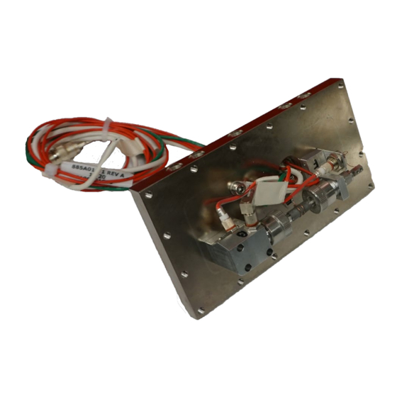
Page 7: Figure 2-3: Dbdid Amplifier Assembly
Legend: Disconnect lines Item Description Reaction gas inlet (plasma gas) Detector inlet (chromatograph column connection for analytes to the detector) Detector vent Open the left side oven door and disconnect the coax cable (item 1 in Figure 2-3) from the DBDID amplifier assembly. -
Page 8: Detector Installation
Reinstall the DBDID detector cover and insert the 16 screws and tighten them to 16 in.-lb, using ABB Tool TL1000/TL1002. There is a small cutout inside of the cover that will need to go back on in the same orientation. -
Page 9: Scheduled Maintenance
(Order 851K006-1 Amp Kit to build the standard 851A094-11412 per included 851J003 bulletin.) Contact your local ABB sales and service representative for specific instructions for ordering spare parts. See the last page of this instruction for contact information. Always include the information listed in Equipment Identifications and Configuration Identification in your request. -
Page 10: Symptom - Plasma Won't Light
To determine the source of the problem: Identify whether the problem is with the chromatographic oven or the detector. In general, if the problem is with component retention times and not component sensitivity, the problem is in the chromatographic oven and not the detector. Ask: “What was the last thing done to the system?”... -
Page 11: Symptom - Excessive Noise
Symptom – Excessive Noise Possible Cause Action(s) Bad electrical connections Check the signal cable connection and the bias voltage cable connection. Check the signal cable shield for fit. The fitting should be snug. Verify connection between ground rod and ground. Air Leak Leak-check all of the fittings within the oven system to verify a leak- free system. -
Page 12: Specifications
UHP (ultra-high purity) for all carrier and reaction gas supplies. Drawings This section contains drawings pertaining to the DBDID as installed in the PGC5000 gas chromatograph. 1 2 | DB DI D | 8 92 J0 09 MN A E... -
Page 13: Figure 5-1: Detector Port Identification
Figure 5-1: Detector port identification Legend: Detector port identification Item Description Purge gas inlet. (Detector assembly purge not used in most applications.) Flameproof breather must remain open or connected to optional purge system. Reaction gas inlet (plasma gas) Purge gas vent. (Detector assembly purge not used in most applications.) Flameproof breather must remain open or connected to optional purge system Detector inlet (chromatograph column connection for analytes to the detector) Detector vent... -
Page 14: Figure 5-3: Diagram Flow Pgc5000 Air And Carrier
Figure 5-3: Diagram flow PGC5000 air and carrier 1 4 | DB DI D | 8 92 J0 09 MN A E... -
Page 15: Figure 5-4: Pgc5000 Oven Electronics Internal Connections Diagram Sheet 1
Figure 5-4: PGC5000 oven electronics internal connections diagram sheet 1 89 2J 00 9MN A E | D B DI D | 1 5... -
Page 16: Figure 5-5: Pgc5000 Oven Electronics Internal Connections Diagram Sheet 2
Figure 5-5: PGC5000 oven electronics internal connections diagram sheet 2 1 6 | DB DI D | 8 92 J0 09 MN A E... - Page 17 We reserve the right to make technical changes or modify the contents of this document without prior notice. With regard to purchase orders, the agreed particulars shall prevail. ABB does not accept any responsibility whatsoever for potential errors or possible lack of information in this document.
Need help?
Do you have a question about the PGC5000 and is the answer not in the manual?
Questions and answers