Sign In
Upload
Manuals
Brands
ABB Manuals
Laboratory Equipment
PGC5000 Gen1 Series
ABB PGC5000 Gen1 Series Manuals
Manuals and User Guides for ABB PGC5000 Gen1 Series. We have
1
ABB PGC5000 Gen1 Series manual available for free PDF download: Operating Instruction
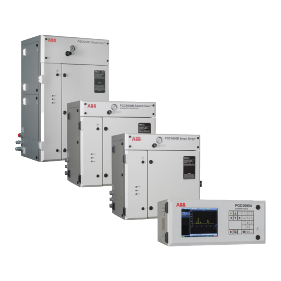
ABB PGC5000 Gen1 Series Operating Instruction (124 pages)
Process gas chromatographs
Brand:
ABB
| Category:
Laboratory Equipment
| Size: 5 MB
Table of Contents
Table of Contents
3
1 Glossary
6
2 Safety and Symbols
7
3 Introduction
8
General
8
Drawings
8
Master Controller
8
Class B Oven
8
Liquid Version
9
Vapor Version
9
Class C Oven
9
Air Purge Systems
9
System Variations
9
4 Installation
10
Safety Considerations
10
Analyzer Location
10
Master Controller
10
Ovens
11
Precautions
11
Preparing for Installation
11
Installation Tools and Equipment
11
Plumbing Installation
12
Gas Requirements
12
Calibration Sample
12
Purge Air Alarm
12
Equipment Mounting
12
Connections
12
Tubing
12
Instrument Air
12
Carrier Gas
12
Burner Fuel
13
Burner Air
13
Sample
13
Hydrogen Gas
13
Vents
13
Liquid Sample Valve
13
Electrical
14
Setting up the Master Controller
14
Single Board Computer Pcb
14
Purge Air Alarm
15
Setting up the Ovens
15
5 Start-Up
16
Introduction
16
Master Controller Controls and Indicators
16
Touchscreen Layout
16
Action Items
17
Function/Navigation Buttons
17
System Information Bar
18
Naming Conventions
18
Keypad
19
Keyboard
19
Oven Controls and Indicators
20
Starting the Analyzer
20
Leak Check Oven
21
Leak Check Carrier Gas Supply Lines
21
Calibrating the Analyzer
21
Validation Run
22
Connecting to the Network
22
Using the Access Control List
24
Logging into PGC5000 Analyzer
24
Access Levels
24
Subscriber List
25
Remote Client
25
Analyzer Shutdown
25
6 Operation
26
Introduction
26
Home Tab
26
Chart Sub-Tab
26
Status Sub-Tab
27
Report Sub-Tab
28
Overlay Sub-Tab
30
Status Tab
31
User Configurable Scopes
32
Configuring Indicators
33
Status Indicator Reset
33
Schedule Tab
33
Maintenance Mode Icon
34
Power Failure Recovery Icon
34
Multiple Oven & Schedule Relationship
35
Queue Sub-Tab
36
Step Sub-Tab
37
Time of Day Sub-Tab
37
Demand Sub-Tab
38
Analysis Tab
38
Chart Sub-Tab
39
Tabular Editor Sub-Tab
40
Normalization
40
New Analysis
41
Analysis Error Messages
42
Loading an Analysis from the Library
44
Running an Existing Schedule
45
Stopping or Pausing Schedules
45
Overlay Sub-Tab
45
Chromatogram Reprocessing
45
Setup Tab
46
File Management
46
System Restore and Recovery
47
System Error Messages
48
Components
49
Streams
50
Master Controller
51
Oven Configuration
53
Oven Buttons
54
Isothermal Oven
57
Electronic Pressure Control
58
Detector Amplifier
59
Subscriber Tab
60
Creating a New Subscriber
61
Adding an Existing Device
62
Subscriber Events
62
Failover Operation
63
Modbus Subtab
63
Program Tab
65
Manual Mode Tab
65
Sample Handling System
65
7 Technical Description
66
Functional Description
66
Detectors
66
Flame Ionization Detector
66
Thermal Conductivity Detector
67
Flame Photometric Detector
67
Optional Discharge Ionization Detector
68
Peak Detection
69
Classic Method of Peak Detection
69
Min-Max Method Overview
69
Min-Max Examples
69
Baseline Correction, Peak Lumping
71
Baseline Correction, Tangent Skim
71
Component Detection (EZ Peak)
72
EZ Peak Calculations
72
Identifying Peaks
72
Single Peak Integration Range
73
Multiple Peak Integration Range
73
Tangent Skim
74
Baseline Drift
74
Time-Coded Functions
74
Auto Zero
75
Autozero
75
Component Min/Max
75
Component Minmax
75
Component RT (EZ Peak)
75
Digital Input Check
75
Do Next if
76
Peak Threshold
76
Pressure Check
76
Pressure Control
76
Pressure Default
76
Script Control
76
Skip Next if
77
Stream Step
77
Temperature Check
77
Temperature Control
77
Temperature Default
77
Unknown Peak
77
Valve on and Valve off
78
Air Purging
78
Y and Z Purge
78
Purge Operation
79
Purge Override Option
80
Purge Override Contacts
80
Remote Client
81
Remote Communications Overview
81
Subscriber Tab Configuration
82
MODBUS Overview
82
PGC5000 MODBUS Configuration
82
MODBUS Slave Communication
83
Client Configurator
84
OPC Communication
86
Input/Output Options
86
Local Input/Output Option
86
Local Output Option Setup
86
Internal Input/Output Option
87
Digital Output
88
Digital Input
89
Analog Input
89
External Input/Output Option
89
8 Operator Troubleshooting
90
Common Issues
90
Oven LED Indicators
90
Indicator Troubleshooting Procedures
90
Status Indicators
91
Diagnostic Displays
96
9 Scripting
99
Introduction
99
Attachment to Analysis Elements
100
Creating a New Script
100
Adding/Running a Script
101
Adding a Line to a Script
101
Deleting a Line
101
Copying a Line
101
Operators
101
Alphabetic Listing
102
ABSOLUTE VALUE Function
102
ACTIVATE STREAM Command
102
ACTUAL RETENTION TIME Function
102
ANALYSIS NAME Function
102
ASC Function
102
BENCHMARK CONCENTRATION Fnctn
102
BPRINT Statement
102
CALIBRATION CONCENTRATION Fnctn
103
CANCEL REQUESTS Command
103
COMPONENT CONCENTRATION Fnctn
103
CHR$ Function
103
CLEAR INDICATORS Command
103
COMMON Floating Point Array
103
COMMON$ String Array
103
COMPONENT NAME$ Function
104
COMPONENT TYPE Function
104
COMPONENT UNITS Function
104
CURRENT STREAM Function
104
DEACTIVATE STREAM Function
104
DIM Statement
104
END Statement
105
END REPORT Statement
105
EXPECTED RETENTION TIME Function
105
EXPONENT Function
105
For
105
GOSUB Statement
105
GOTO Statement
106
IF Statement
106
INDICATOR Function
106
INJECT TIME Function
106
INTEGER TYPE Conversion Routine
106
LENGTH Function
106
LOGARITHM BASE TEN Function
107
LPRINT Statement
107
MID$ Function
107
NATURAL LOGARITHM Function
107
NUMBER COMPONENTS Function
107
OUTSTANDING REQUESTS Function
107
PEAK AREA Function
107
PEAK CREST AMPLITUDE Function
108
PEAK END AMPLITUDE Function
108
PEAK END TIME Function
108
PEAK NEGATIVE AREA Function
108
PEAK POSITIVE AREA Function
108
PEAK START AMPLITUDE Function
108
PEAK START TIME Function
109
PURGING STREAM Function
109
Put Component Concentration
109
PUT PRESSURE of a Zone Command
109
PUT RESPONSE FACTOR Command
109
Put Temperature of a Zone
109
READ ANALOG INPUT Function
109
READ DIGITAL INPUT Function
110
REMARKS Statement
110
REQUEST ANALYSIS Command
110
RESPONSE FACTOR Function
110
SCHEDULE ABORT Function
110
SCHEDULE NAME Function
110
SCHEDULE RUN Function
110
SCHEDULE STOP Command
110
SET BASIC ALARM Command
110
SLEEP Function
111
SQUARE ROOT Function
111
START REPORT Statement
111
STREAM NAME Function
111
STREAM STATUS Function
111
TIME$ Function
111
TOTAL PEAK AREA Function
111
Value Function
112
VALVE Command
112
WRITE ANALOG OUTPUT Command
112
WRITE DIGITAL OUTPUT Command
112
Y2X Function
112
ZONE PRESSURE Function
112
ZONE TEMPERATURE Command
112
Valve on
112
10 Version Upgrade
113
Determining Eqpt to be Upgraded
113
PC Upgrading
113
Gateway Upgrading
116
Upgrading Older Pgc5000S
119
Advertisement
Advertisement
Related Products
ABB PGC5000 Series
ABB PGC5000TPGC
ABB PGC5007
ABB PGC5009
ABB PGC5000 Generation 2
ABB PGC5000A
ABB PGC5000 GEN 2
ABB PGC2000
ABB PGC1000
ABB PGS100
ABB Categories
Industrial Equipment
Controller
Measuring Instruments
Battery Charger
DC Drives
More ABB Manuals
Login
Sign In
OR
Sign in with Facebook
Sign in with Google
Upload manual
Upload from disk
Upload from URL