Laars FT Series Installation And Operation Instruction Manual
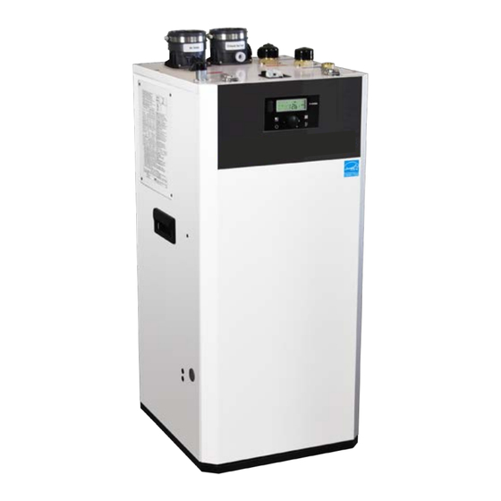
Floor standing, modulating gas, condensing, heating only boiler
Hide thumbs
Also See for FT Series:
- User manual ,
- Installation and operation instructions manual (100 pages) ,
- Installation and operation instruction manual (100 pages)
Table of Contents
Advertisement
Quick Links
Installation and Operation Instructions
FOR YOUR SAFETY: This product must be installed and serviced by a professional service technician,
qualified in hot water boiler and heater installation and maintenance. Improper installation and/or operation
could create carbon monoxide gas in flue gases which could cause serious injury, property damage, or
death. Improper installation and/or operation will void the warranty.
If the information in this manual is not
followed exactly, a fire or explosion may
result causing property damage, personal
injury or loss of life.
Do not store or use gasoline or other
flammable vapors and liquids in the vicinity of
this or any other appliance.
WHAT TO DO IF YOU SMELL GAS
• Do not try to light any appliance.
• Do not touch any electrical switch; do not
use any phone in your building.
• Immediately call your gas supplier from a
nearby phone. Follow the gas supplier's
instructions.
• If you cannot reach your gas supplier, call
the fire department.
Installation and service must be performed
by a qualified installer, service agency, or gas
supplier.
Installation and Operation
Instructions for
Floor Standing, Modulating
Gas, Condensing, Heating Only Boiler
Model FTHF199N
199,000 BTU/h •
WARNING
Natural Gas (NG) - Factory Configuration
•
Propane - Field-Convertible
AVERTISSEMENT
Assurez-vous de bien suivres les instructions
données dans cette notice pour réduire au
minimum le risque d'incendie ou d'explosion
ou pour éviter tout dommage matériel, toute
blessure ou la mort.
Ne pas entreposer ni utiliser d'essence ou ni
d'autres vapeurs ou liquides inflammables dans
le à proximité de cet appareil ou de tout autre
appareil.
QUE FAIRE SI VOUS SENTEZ UNE ODEUR DE
• Ne pas tenter d'allumer d'appareils.
• Ne touchez à aucun interrupteur. Ne pas vous servir
des téléphones dans le bâtiment où vous vous
trovez.
• Appelez immédiatement votre fournisseur de
gaz depuis un voisin. Suivez les instructions
du fournisseur.
• Si vous ne pouvez rejoindre le fournisseur de
gaz, appelez le sservice des incendies.
L'installation et l'entretien doivent être assurés par
un installateur ou un service d'entretien qualifié
ou par le fournisseur de gaz.
Document 1510B
GAZ:
Advertisement
Table of Contents

Related Manuals for Laars FT Series


Summary of Contents for Laars FT Series
- Page 1 Installation and Operation Instructions Document 1510B Installation and Operation Instructions for Floor Standing, Modulating Gas, Condensing, Heating Only Boiler Model FTHF199N 199,000 BTU/h • Natural Gas (NG) - Factory Configuration • Propane - Field-Convertible FOR YOUR SAFETY: This product must be installed and serviced by a professional service technician, qualified in hot water boiler and heater installation and maintenance.
-
Page 2: Table Of Contents
4.21 Control Board, Electrical Diagram ....54 NOTE: For Cascading Installations, please refer to 4.22 Ladder Diagram ..........55 document 1349 ‘Cascading the FT Series Boiler’, 4.23 Electrical Connections (table) ......56 available online. Location and Clearances ........12 SECTION 5 Control Display and Operation Flooring &... -
Page 3: Section 1 Introduction About This Installation Manual
The FT Series Floor Standing, Heating Only Boiler Page 3 SECTION 1 Introduction For details on Combustion Air About this and Venting, (Pages 14-32) Installation Manual For details on Plumbing for Central Heat, (Pages 43-50) All installations must be made in accordance with 1) American National Standard Z223.1/... -
Page 4: Included In The Box
Model Nomenclature (model number) Model number The Model Nomenclature is shown on your Rating Plate and consists of a series of letters and numbers (Nomenclature) that further identifies the characteristics of your FT Series Heating Only Boiler. FUEL SERIES SIZE... -
Page 5: Specifications
The FT Series Floor Standing, Heating Only Boiler Page 5 Specifications, 199 Model Name FTHF199N 199,000 Btu/h Gas Input Rate 19,900 Btu/h Indoor / Floor stand type Installation Sealed Combustion Direct / Single Vent / Concentric Flue System Vent 2˝(50ft), 3˝(100ft) Schedule 40 CPVC, PP, PVC,... -
Page 6: Dimensions
Page 6 Dimensions 16˝ 15-5/8˝ 12-7/8˝ 9-1/2˝ 4-3/4˝ 1-3/4˝ Description Diameter Air Intake Collar 3” Vent Pipe Collar 3” 1-1/2” NPT Boiler Supply Boiler Return 1-1/2” NPT 3/4” NPT Gas Inlet Condensate Line 1/2” (no NPT) Pressure Relief Valve & Air Vent 1”... -
Page 7: Names Of Components
The FT Series Floor Standing, Heating Only Boiler Page 7 Names of Components Name of Component Pressure Relief Valve Air Vent (air eliminator) Boiler Return Connection Boiler Supply Connection Vent Pipe Collar Boiler Pressure Gauge Air Intake Collar Gas Inlet Adapter... -
Page 8: Product Flow Paths And Characteristics
Page 8 Product Flow Paths and Characteristics Central Heating flow. Boiler Heating Mode. 2.5.1 Water in the heating system flows through the low loss header (LLH) boiler pump heats water in the boiler and is circulated through LLH. System pump or individual zone pumps are required to pull heated water from CH supply connection and return water to CH return connection. -
Page 9: Section 3 Safety Regulations Safety Symbols
The FT Series Floor Standing, Heating Only Boiler Page 9 SECTION 3 Safety Regulations WARNING Safety Symbols FOR YOUR SAFETY READ BEFORE This manual provides Safety Symbols. When the user OPERATING fails to adhere to the following requirement, it may... -
Page 10: Safety Precautions And Proper Use
Page 10 Safety Precautions and Proper Use (continued) Be aware of the location of the gas shut-off valve This appliance must be installed in accordance with and operation method. Close the gas shut-off valve local codes if any; if not, follow ANSI Z224.1/NFPA immediately if the appliance is subjected to fire, 54 or CAN/CSA B149.1, Natural Gas and Propane overheating, flood, physical damage, or any other... - Page 11 The FT Series Floor Standing, Heating Only Boiler Page 11 Before Operation 2. Caution for Ventilation Make sure that there is sufficient inflow and outflow of air ventilation while using the unit. 1. Check the Gas Type (NG / Propane) when using If the ventilation is improper, combustion quality may or moving the unit for the first time.
-
Page 12: Section 4 Installation
Page 12 SECTION 4 Installation Location and Clearances WARNING Installations must comply with The FT floor boiler must be installed on a level surface • All the local, state, provincial, and national codes, of sufficient strength and follow the clearances listed in laws, regulations and ordinances. -
Page 13: Flooring & Leveling
The FT Series Floor Standing, Heating Only Boiler Page 13 Flooring & Leveling WARNING Make sure that the floor and structure of the installation location are sufficient to support the full installed weight of the boiler, including water content of the heat exchanger and related piping. Failure to ensure the floor and structure of the installation location are structurally sound before installation of the boiler can result in structural failure, substantial property damage, severe personal injury, or death. -
Page 14: Combustion Air
Page 14 Combustion Air vertical or horizontal duct to the outdoors or spaces FT boilers must have provisions for combustion and ventilation air in accordance with the applicable that directly communicate with the outdoors and shall requirements for Combustion Air Supply and Ventilation have a minimum free area of 1 square inch per 3000 in the National Fuel Gas Code, ANSI Z223 1;... - Page 15 The FT Series Floor Standing, Heating Only Boiler Page 15 NOTICE AVIS The instructions for the installation of the venting Les instructions d'installation du système system shall specify that the horizontal portions of d'évacuation doivent préciser que les sections the venting system shall be supported to prevent horizontales doivent être supportées pour prévenir...
-
Page 16: Venting (Exhaust)
Page 16 Venting (Exhaust) WARNING All venting must be installed according to this manual NOTICE and any other applicable local codes, including but not limited to, ANSI Z224.1/NFPA 54, CAN/CSA DO NOT COMMON VENT FT UNITS. FT units are never permitted to share a vent B149.1 and ULC-S636. -
Page 17: General Location Guideline
The FT Series Floor Standing, Heating Only Boiler Page 17 4 . Venting system components can only WARNING be mixed with alternate manufacturers’ Failure to vent this Boiler in accordance with these certified components when clearly listed instructions could cause a fire, resulting in severe in the manufacturers Installation Manual. -
Page 18: Locations For Vent Pipe Terminator
Page 18 Locations for Vent Pipe Terminator Canadian Installations 1 U.S. Installations 2 A = Clearance above grade, veranda, porch, deck, or balcony B = Clearance to window or door that may be ● 6 in (15 cm) for appliances ≤ 10,000 Btuh (3 kW) ●... -
Page 19: Venting Requirements In The Commonwealth Of Massachusetts
The FT Series Floor Standing, Heating Only Boiler Page 19 Venting Requirements in the 4.6.1 Commonwealth of Massachusetts Inspection The state or local gas inspector of the In Massachusetts the following items are required if side-wall horizontally vented gas fueled appliance shall... -
Page 20: Common Vent Test
Page 20 Common Vent Test NOTE: This section does not describe a method for common venting FT units. It describes what must be done when an existing unit is removed from a common vent system. AVIS Au moment du retrait d'une chaudière existante, les mesures suivantes doivent être prises pour chaque appareil toujours raccordé... -
Page 21: Air Supply And Vent Connections
**When using 2" Combustion Air & Vent pipe, Propane Models are limited to 25 equivalent feet (7.5 M) of vent and 25 equivalent feet (7.5 M) of combus The FT Series Floor Standing, Heating Only Boiler Page 21 Air Supply and Vent Connections Vent / Air Pipe Lengths for dual pipe venting systems. -
Page 22: Indoor Combustion Air
Page 22 Indoor Combustion Air 4.8.2 Read and follow section 4.3 Guidelines first. 1. Insert the termination end cap into the intake air duct. 2. Provide two openings to allow for circulation of combustion air as specified by ANSI Z224.1/NFPA 54. In Canada refer to CAN/CSA B-149.1 NOTE: The FT needs fresh air for safe operation and must be installed so there are provisions for... - Page 23 The FT Series Floor Standing, Heating Only Boiler Page 23 4.9 Vent / Air Pipe Termination (continued) 4.9.2 Horizontal Vent Termination • Direct Vent - Sidewall Termination Exterior Wall Vent Screens are required 1” MIN Exhaust Elbow 12” MIN 12” MIN...
- Page 24 Page 24 • Direct Vent - Optional Side wall Terminations 4.9 Vent / Air Pipe Termination (continued) Low Profile Vent Termination 4.9.3 • Direct Vent - Optional Side wall Term Follow the manufacturer’s installation guidelines included with the Low Profile Vent Termination Kit NOTICE and Concentric Vent Kit for installation requirements and guidelines.
-
Page 25: Concentric Venting Systems
The FT Series Floor Standing, Heating Only Boiler Page 25 4.10 When replacing an Endurance model 4.10.1 Concentric Venting Systems The following concentric venting systems and components are approved for use with the FT floor standing boilers: Table 6: Approved Heat-Fab SC series 3˝ x 5˝ stainless steel concentric venting components. -
Page 26: Installation Of A New Concentric Stainless Steel Venting System
Page 26 4.10.2 Installation of a Complete New Concentric 5) Properly support each horizontal and vertical section at least every 4 ft and at each elbow. Finish Stainless Steel Venting System. the vertical section by the installation of the SCO3VT For a vertical venting system, locate the boiler to affect Vertical Terminal Adapter on the last piece of vertical the shortest possible vent length run with the... -
Page 27: Existing Stainless Steel Venting
The FT Series Floor Standing, Heating Only Boiler Page 27 5) After completion of the venting system, review all changed, 45° offset fittings will be required to bring the joints of the venting installation and make sure that all centerline of the FT vent forward to align with the locking screws of the adjoining vent sections are all existing vent assembly. -
Page 28: Installation Of Duravent Pps
Page 28 4.10.4 New Installation of Duravent PPS each piece, not to exceed 6-1/2". Assemble the parts in the following order: Concentric System 1) Insert a stainless steel to PP adaptor, (#4), into The FT boiler has separate Combustion Air and Vent each of the FT boiler sockets and ensure that they connections. -
Page 29: Duravent Pps Concentric System To An Existing Heat-Fab Sc Venting System
The FT Series Floor Standing, Heating Only Boiler Page 29 aligned with the Vent socket on the FT Boiler. Slide the 17.75” pipe down through the stainless steel to PP 8) Additional concentric Duravent PP components can be purchased from your local wholesaler. - Page 30 Page 30 If the existing venting system is a horizontal run, the slope of that system will need to be changed. As installed, that system required a downward slope of ¼” per foot toward the outside wall. The venting system for FT boiler requires a slope of 3/8” per foot back toward the boiler so that condensate will drain back to the boiler and be eliminated.
- Page 31 The FT Series Floor Standing, Heating Only Boiler Page 31 Stub-out Kit FT3002 Description ITEM QUAN- PART NUM- TITY NUMBER 820014497 Concentric Adaptor 80/80 - 80/125 820001613 3˝ Diameter PP 12˝ Pipe Length 820019072 3˝ Diameter PP 17.750˝ Pipe Length 810004167 3˝...
-
Page 32: Flexible Chimney Liner Venting
Page 32 Table 8: Approved components for use in 3˝ Vertical PP Flex venting. FT3003 PP to Heat-Fab Kit Part Number Description 3PPS-FLEX50 3˝ Diameter 50´ Flex PP 3PPS-FKC 3˝ Flex kit 3PPS-72C 3˝ 6´ PP Pipe 3PPS-E90C 3˝ PP elbow 3PPS-03PVCM-3PPF 3˝... -
Page 33: Gas Supply And Piping
The FT Series Floor Standing, Heating Only Boiler Page 33 Gas Supply and Piping 4.11 WARNING: Gas piping should be supported by suitable hangers or Open flame can cause gas to ignite and result in floor stands, by the appliance. - Page 34 Page 34 4.11 Gas Supply and Piping (cont) The gas connection fitting is, 3/4” male NPT on To facilitate any future maintenance, it is also recommended that an approved gas union fitting FTCF199 models. be installed in the supply line between the shut-off The supply line must be sized for the maximum valve and the 3/4˝...
- Page 35 The FT Series Floor Standing, Heating Only Boiler Page 35 Suggested Natural Gas (NG) Layout NOTE: Total gas supply capacity must not be less than the total demand capacity of the connected appliances. Gas Regulator (Supply Press 12˝ ) Suggested Propane Layout...
-
Page 36: Gas Supply Pressure
Page 36 4.12 Gas Supply Pressure Refer to the illustration. Inlet Gas Pressure Port Gas Outlet / Manifold Pressure Port Offset Adjustment. Do Not Adjust without using a combustion analyzer to verify adjustment. Adjust ONLY when in MIN Fire and when using a combustion analyser. See Section 4.13 for step by step details. -
Page 37: Adjusting Combustion
The FT Series Floor Standing, Heating Only Boiler Page 37 4.13 Adjusting Combustion Note: When in Low Fire the burner should remain 1. Remove the front cover by opening the two clips on. If the flame dies out after a few seconds while in... -
Page 38: High Altitude Installations
Page 38 Adjusting Combustion (continued) Liquid Propane Natural Gas Manifold Pressure 2” VENT 3” VENT 2” VENT 3” VENT -0.129” WC -0.314” WC -0.169” WC -0.173” WC Max Fire FTHF199 -0.015” WC -0.015” WC -0.015” WC -0.015” WC Min Fire Table 11. -
Page 39: Natural Gas To Propane Conversion
The FT Series Floor Standing, Heating Only Boiler Page 39 4.15 Natural Gas to Propane Conversion The FT floor standing, condensing boiler is config- ured for Natural Gas (NG) from the factory. A Pro- pane Conversion Kit is included with every FT. The gas conversion kit will show you how to convert your FT boiler to propane. - Page 40 Page 40 The FT Series, Wall Combi, Gas Conversion Kit Document 4388 4.15 Natural Gas to Propane Conversion (cont) Figure A Figure B Gas Valve Figure B Combustion Test Port Figure C ORIFICE FTCW140 Flat Side PACKING Inward FTCW199 Gas Valve...
- Page 41 The FT Series Floor Standing, Heating Only Boiler Page 41 4.15 Natural Gas to Propane Conversion (continued) Shown is a Model 199 Natural Gas with 3” Venting. Propane 2˝ Vent 3˝ Vent High Natural Fire Fire Table B DIP Switch Settings *DIP Switches #7 and #6 are Maximum and Minimum fire test Switches which are used only when setting up combustion (See Section 4.13)
- Page 42 Page 42 The FT Series, Wall Combi, Gas Conversion Kit Document 4388 4.15 Natural Gas to Propane Conversion (continued) NOTE: Installer is required to verify combustion settings as part of the installation process. CO should not exceed 200 ppm. Natural Gas (NG)
-
Page 43: Plumbing Guidelines
The FT Series Floor Standing, Heating Only Boiler Page 43 4.16 Plumbing Guidelines 4.16.1 External Plumbing and Water CAUTION Connection Guidelines The built-in LLH allows direct piping of system - Ensure pipe material meets local codes and industry standards. supply and return connections to their respective connections on top right side of the boiler. -
Page 44: Single Zone Heating And Indirect Dhw Tank
Page 44 Plumbing Guidelines (continued) 4.16.4 Single or dual zone heating and indirect DHW tank MULTIZONE HEATING, ZONE VALVES & INDIRECT TANK Expansion tank (Diaphragm-type) Automatic air vent Air separator Circulation pump Circulation pump with built-in IFC Check Valve Check valve Drain valve Shut-off valve Gate valve... - Page 45 The FT Series Floor Standing, Heating Only Boiler Page 45 Wiring, Single or dual zone Heating with Indirect DHW Tank Temperature L-T/T Sensor or Thermostat Pump Pump Temperature Aquastat Thermostat L-T/T Zone Sensor or Thermostat (14 Gauge Wire) System Aquastat...
-
Page 46: Zoning With Zone Valves And Indirect Dhw Tank Pump
Page 46 4.16.5 Zoning with zone valves and indirect DHW tank pump. MULTIZONE HEATING, ZONE VALVES & INDIRECT TANK Expansion tank (Diaphragm-type) MAKE UP WATER Automatic air vent Air separator Circulation pump EXPANSION Circulation pump with built-in IFC TANK BACKFLOW Check Valve Check valve PREVENTER... - Page 47 The FT Series Floor Standing, Heating Only Boiler Page 47 Wiring with zone valves and indirect DHW tank pump THERMOSTAT THERMOSTAT THERMOSTAT 24 VAC INPUT MODE ZONE 4 PRIORITY NORMAL RESET POWER IN ZONE 1 ZONE 2 ZONE 3 ZONE 4...
-
Page 48: Zoning With Pumps And Indirect Dhw Tank Pump
Page 48 4.16.6 Two temperature system: zoning with pumps and indirect DHW tank pump. TWO TEMP HEATING, CIRCULATORS & INDIRECT TANK Expansion tank (Diaphragm-type) MAKE UP WATER Automatic air vent Air separator Circulation pump Circulation pump with built-in IFC Check Valve Check valve Drain valve Shut-off valve... - Page 49 The FT Series Floor Standing, Heating Only Boiler Page 49 Wiring of two temperature system with multiple pumps and indirect DHW tank pump. T'STATS ZONE 4 SLAVE 1234 PLUG-IN CARDS PRIORITY MASTER LO TEMP MID TEMP HI TEMP FOUR ZONE SWITCHING RELAY...
-
Page 50: Pressure Relief Valve
Page 50 4.17 Pressure Relief Valve External pressure relief valves must be installed. Ensure that the maximum BTU/H rating on the Observe the following. Failure to comply with the pressure relief valve is equal to or greater than the maximum input BTU/H rating of the boiler. guidelines on installing the pressure relief valve and discharge piping can result in personal injury, death Pressure Relief Valve must be installed on the provided... -
Page 51: Disposal Of Condensate
The FT Series Floor Standing, Heating Only Boiler Page 51 4.18 Disposal of Condensate • If desired, a discharge 1/4” or 3/8” can be routed by removing yellow cap from the top right rear corner • High efficiency gas condensing boilers create and routing the hose down to the condensate pump. -
Page 52: Electrical Wiring Connections
Page 52 4.19 Electrical Wiring Connections Field Wiring: Top of terminals Install wiring as shown below. L/ZC L/ZC 0~10V AC24V CASCADE SYSTEM L-T/T SENSOR MAIN POWER SYSTEM PUMP L-T/T PUMP DHW PUMP ERROR INPUT OUTPUT WARNING Install wiring and electrically ground boiler in accordance with authority having jurisdiction or, in the absence of such requirements, follow the National Electrical Code, NFPA 70, and/or CSA C22.1 Electrical Code-Part 1 in Canada. -
Page 53: Dip Switches
The FT Series Floor Standing, Heating Only Boiler Page 53 4.19 Electrical Wiring Connections (continued) 4.20 DIP Switches Shown is a Model 199 Natural Gas with 3” Venting. 2˝ Vent Propane 3˝ Vent High Natural Fire Fire *DIP Switches #7 and #6 are Maximum and Minimum fire test Switches which are used only when setting up combustion (See Section 4.13). -
Page 54: Control Board, Electrical Diagram
Page 54 4.21 Control Board, Electrical Diagram Control Board... -
Page 55: Ladder Diagram
The FT Series Floor Standing, Heating Only Boiler Page 55 4.22 Ladder Diagram... -
Page 56: Electrical Connections (Table)
Page 56 4.23 Electrical Connections, (table) Connector HT SELV Description #, Location, Type Label GROUND Power Supply Line HT (120V~) Heating /CP1 HT (120V~) System Pump HT (120V~) Igniter HT (120V~) Boiler Pump 65001WS-12 Gas Valve HT (120V~) Ground Power Supply Neutral HT (120V~) AC Power COM Line HT (120V~) - Page 57 The FT Series Floor Standing, Heating Only Boiler Page 57 Electrical Connections , (table) (continued) Connector HT SELV Description #, Location, Type Label SELV (5V) Flame Detect Sensor OP.S Operating water temperature sensor SELV (5V) DH.S Venting (exhaust) temperature sensor...
-
Page 58: Section 5 Control Display And Operation
Page 58 SECTION 5 Control Display and Operation Control Dial and Buttons (Status Light) (Constant green when operating normally) The Control Display The Control Display has a Control Dial (E), 4 Buttons (A,B,C,D), and a Liquid Crystal Display (with 72 back lit segments). -
Page 59: Lcd Overview
The FT Series Floor Standing, Heating Only Boiler Page 59 LCD Overview... -
Page 60: Operating Mode
Page 60 Operating Mode boiler pump is operating... -
Page 61: Setting The Clock
The FT Series Floor Standing, Heating Only Boiler Page 61 Setting the Clock... -
Page 62: Set Point Change Mode
Page 62 CH Set Point Change Mode ▪ CH set point Change Mode (This mode is only functional when the outdoor sensor (O/S) is not connected.) ▪ In accordance with the United States Energy Policy and Conservation Act, this boiler is equipped with outdoor reset capability, a feature that saves energy by reducing boiler water temperature as heating load decreases Refer to Section 5.9 regarding the O/S details. -
Page 63: Status Display Mode
The FT Series Floor Standing, Heating Only Boiler Page 63 Status Display Mode 32°F. -
Page 64: Installer Mode
Page 64 Installer Mode Index Description Default Parameter Numbers Check last 10 error codes (E0 - E9) 1: EH Error history up to 10 Select “ON“ to delete error code history 2: cE Delete Error history Range: ON or OFF System initialize Select “ON“... - Page 65 The FT Series Floor Standing, Heating Only Boiler Page 65 5.7 Installer Mode (continued) Index Description Default Parameter Numbers Sets the design supply water temperature based on the maximum outdoor design temperature. Minimum supply temperature must be 130°F Minimum Supply 7: cL set at least 9°F below the maximum supply temperature.
- Page 66 Page 66 Index Description Default Parameter Numbers Cascade Number Range: 0 (Master), 1(slave 1), ..,19(slave 19) 27: Cn Cascade Number “29: CP” has to be set with the total number of units in the cascade before “28: Cn” can be set. Number of units cascaded.
-
Page 67: Storage Mode
The FT Series Floor Standing, Heating Only Boiler Page 67 Storage Mode 21:dH... -
Page 68: Outdoor Reset Adjustment
Page 68 Outdoor Reset Adjustment Outdoor Reset varies the control set point based on the outdoor temperature. The reset function works as shown in Figure ‘CH Outdoor Reset’. When the outdoor air “high outdoor temperature 4:OH temperature reaches set point”, the control point setting is adjusted to 7:cL “low boiler temperature set point”. -
Page 69: Error Mode
The FT Series Floor Standing, Heating Only Boiler Page 69 5.11 Error Mode Flashing... -
Page 70: Section 6 Error Codes 6.1 Error Code Tables
Page 70 Error Code Tables SECTION 6 Error Codes Error Error Code Recover Possible Remedies Code Description methods Press the Power button to clear the Error Code. If Error happens again: 1. Monitor the gas pressure to the appliance while in operation. Ensure pressure is between 3.5” to 10.5” WC (Nat. - Page 71 The FT Series Floor Standing, Heating Only Boiler Page 71 SECTION 6. Error Codes (continued) Recover Error Error Code Possible Remedies Code Description methods Possible Remedies : This Error Code will go away when exhaust temperature decreases. Venting If Error happens again: (Exhaust) 1.
- Page 72 Page 72 Recover Error Error Code Possible Remedies Code Description methods This Error Code will go away when the condition is remedied. If Error happens again: MCU self 1. Turn power OFF and ON at the main power switch internal to the appliance. Soft Lock diagnostics fault 2.
-
Page 73: Fault Tree Analysis
The FT Series Floor Standing, Heating Only Boiler Page 73 Fault Tree Analysis 1. Flame detection... - Page 74 Page 74 6.2 Fault Tree Analysis (cont) 2. Gas Detection 3. ‘Storage’, ‘DHW’, ‘OP’, ‘CH overheat’, ‘Exhaust heat’ Sensor detects Error code contents DHW NTC open or short OP NTC open or short Exhaust NTC open or short...
-
Page 75: Diagnostics
The FT Series Floor Standing, Heating Only Boiler Page 75 SECTION 7 Trouble Shooting Diagnostics Question Answer The blower is still oper- This is normal because the blower keeps operating for 1 minute to vent (exhaust) the ating after the combus- flue gas from the chamber once the combustion has stopped. -
Page 76: Suggested Corrective Actions
Page 76 Suggested Corrective Actions This controller is able to record information about the boiler’s condition at the time of the five previous faults or errors. Refer to the Section ‘5.11 Error Mode’ of this manual. Corrective Action(s) Display Condition Diagnostic Check wiring for short Correct wiring per wiring diagram... - Page 77 The FT Series Floor Standing, Heating Only Boiler Page 77 7.2 Suggested Corrective Actions (continued) Corrective Action(s) Fault Condition Diagnostic Check all the temperature readings of the boiler on the DIAGNOSTICS - Occurs when TEMPERATURES menu to determine if any...
- Page 78 Page 78 this page intentionally left blank.
-
Page 79: Section 8 Maintenance
The FT Series Floor Standing, Heating Only Boiler Page 79 SECTION 8 Maintenance - Check the power source. Annual startup & Make sure that the power cord is correctly connected. general maintenance The main power line is connected to the manual switch box inside the boiler. - Page 80 Page 80 - Check the air vent If the air vent valve seems to work freely without If the valve continues to weep, contact your qualified leaking, close cap A fully. service technician for inspecting the valve and system. Loosen cap “A” one turn to allow vent to operate. If water does not flow from the valve even though If vent does not operate correctly, replace the vent.
-
Page 81: Freeze And Inhibitor Protection
The FT Series Floor Standing, Heating Only Boiler Page 81 Freeze and Inhibitor Protection FT Boilers are certified for indoor use only, and are WARNING not design-certified for placement outdoors. Proper precautions for freeze protection are Do NOT use automotive antifreeze or recommended for boiler installations in areas where ethylene glycol. -
Page 82: Quick View
Page 82 SECTION 9 Installation Check Quick View Before Installing - Make sure that there is enough space for installing DHW hot and cold, possible DHW recirc, space heating and gas piping. Verify vent/air termination is located as required. - Propane boilers require a propane conversion kit, conversion parts and documentation are included. -
Page 83: Final Check Lists
The FT Series Floor Standing, Heating Only Boiler Page 83 Final Check Lists Final check : Connecting the power supply Final check: Installation Conditions. • Please check that the power is 120V AC. • Is the Boiler placed level on a floor with sufficient •... -
Page 84: Section 10 Parts List And Illustrations
Heat Exchanger Sub Bracket FT3030 PCB Control Sub Bracket FT3031 Bracket FT3032 PCB Control Bracket FT3033 Main PCB FT3130 Front Cover Ass'y (Laars) FT3171 Front Cover Ass'y (Bradford White)) FT3170 Handle FT3036 Tank bracket FT3037 Casing Ass’y FT3172 AS Cover... - Page 85 Stainless Band (Ø100) FT1603 Packing FT1604 The FT Series Floor Standing, Heating Only Boiler Page 85 3 inch Air Intake Collar FT3011 Air Filter FT3012 Air Filter Packing FT3013 B-13 M4 x 14mm Pan Head Screw (coarse thread) Vent Pipe Collar Ass'y...
- Page 86 Page 86 Heat Exchanger and Tank Assembly 58-2 B-11 58-1 B-12 63-2 63-3 63-1 B-13 58-3 B-10 60-1 60-2 O-22 60-3 B-14 B-15 64-2 60-5 60-4 64-1 60-6 60-7 64-3...
- Page 87 The FT Series Floor Standing, Heating Only Boiler Page 87 Heat Exchanger and Tank Parts Part Description Number Exhaust Duct Ass'y FT3090 58-1 Exhaust Duct 58-2 Exhaust Overheat Sensor FT1307 58-3 Exhaust Duct Packing (Lower) FT2036 O-Ring P7 FT1601 B-11 M4 x 9mm Hex Head Screw (coarse thread) Heat Exchanger Ass’y...
- Page 88 Page 88 Tank and Water Pipe Parts Part No. Description Number DHW Water Tank Ass'y FT3164 39-1 CH Return bottom Pipe 1 29-1 Stainless Band (Ø165) FT1813 Piping Clip 1 FT1107 Piping Clip 2 FT1108 Internal Circulation Pipe 1 Ass'y FT3300 O-24 O-Ring P24...
- Page 89 The FT Series Floor Standing, Heating Only Boiler Page 89 Tank and Water Pipe Assembly B-10 36-1 B-10 B-10 41-1 37-1 O-24 38-1 30-1 O-24 O-24 29-1 39-1 38-1 31-1 O-24 40-1 32-1 O-24 O-24 33-1 35-1 O-24 34-2 34-1...
- Page 90 Page 90 Fan and Gas Valve Assembly B-18 B-18 67-3 B-18 65-1 67-3 67-4 65-2 65-1 65-3 67-4 65-2 65-3 67-1 67-1 70-1 B-19 B-19 65-4 67-2 65-4 67-2 B-18 B-18 68-1 65-1 68-2 65-2 65-3 B-17 66-5 B-17 66-5 B-17 66-4 66-4...
- Page 91 The FT Series Floor Standing, Heating Only Boiler Page 91 Fan and Gas Valve Parts Part Description Number Fan Guide Ass'y FT2087 65-1 Fan Guide 65-2 Fan Rubber Packing#2 FT2020 65-3 Damper Body Ass'y FT2044 65-4 Fan Guide Packing FT1772 Fan Ass’y...
- Page 92 The FT Series Floor Standing, Heating Only Boiler Accessory Items Description Part Number Pressure Relief Valve FT1500 Air Vent FT3117 Brass Adaptor FT3118 3/4" Brass Plug FT3119 Outdoor Temp. Sensor FT1501 Bird Screen 3"(Qty 2) FT1730 Spare Parts Kit FT3165...
Need help?
Do you have a question about the FT Series and is the answer not in the manual?
Questions and answers
MY FT series Boiler does not provide hot water
Your Laars FT Series boiler may not be providing hot water due to several possible issues:
1. Temperature Sensor Fault – If a temperature sensor is electrically shorted (SHORT) or has become disconnected (OPEN), the boiler may not function properly. Check the DIAGNOSTICS - TEMPERATURES menu to see if any sensors are displayed as SHORT or OPEN. If so, reset the system using the manual reset screen and check wire harness connections.
2. Flame Fault – If the boiler detects no flame when there should be one, it may not generate heat. Check for flame at the burner via flame current with the burner off. If necessary, reset the system using the manual reset screen.
3. Incorrect Combustion – If the burner is operating too hot, the system may not function correctly. Inspect the flame and conduct a combustion test to ensure proper operation.
4. Power or Control Issues – Ensure the display is powered on and system variables are correctly set. Use the control buttons to check or adjust heating set points.
If these checks do not resolve the issue, contact a qualified service technician for further inspection and repairs.
This answer is automatically generated
Boiler does not provide enough hot water
The Laars FT Series boiler may not provide enough hot water due to the following reasons:
1. The gas supply type may be incorrect.
2. The supply and manifold gas pressures may not be within specifications.
3. The water flow sensor with three wires may not be properly connected.
4. The setting temperature on the unit may be too low.
5. The filter in the cold water supply line may be clogged with debris.
6. The cold and hot water lines may be plumbed in reverse.
7. The water lines may be frozen.
8. There may not be enough water flow, as the unit activates only when inlet water flow is above 0 GPM.
This answer is automatically generated