Laars FT Series Installation And Operation Instructions Manual
Floor standing, modulating gas, condensing, combination boiler
Hide thumbs
Also See for FT Series:
- User manual ,
- Installation and operation instructions manual (100 pages) ,
- Installation and operation instruction manual (100 pages)
Table of Contents
Advertisement
Installation and Operation Instructions
FOR YOUR SAFETY: This product must be installed and serviced by a professional service technician,
qualified in hot water boiler and heater installation and maintenance. Improper installation and/or operation
could create carbon monoxide gas in flue gases which could cause serious injury, property damage, or
death. Improper installation and/or operation will void the warranty.
If the information in this manual is not
followed exactly, a fire or explosion may
result causing property damage, personal
injury or loss of life.
Do not store or use gasoline or other
flammable vapors and liquids in the vicinity of
this or any other appliance.
WHAT TO DO IF YOU SMELL GAS
• Do not try to light any appliance.
• Do not touch any electrical switch; do not
use any phone in your building.
• Immediately call your gas supplier from a
nearby phone. Follow the gas supplier's
instructions.
• If you cannot reach your gas supplier, call
the fire department.
Installation and service must be performed
by a qualified installer, service agency, or gas
supplier.
Installation and Operation
Instructions for
Floor Standing, Modulating
Gas, Condensing, Combination Boiler
Model FTCF199N
199,000 BTU/h
WARNING
•
Natural Gas (NG) - Factory Configuration
•
Propane Gas (LP) - Field-Convertible
AVERTISSEMENT
Assurez-vous de bien suivres les instructions
données dans cette notice pour réduire au
minimum le risque d'incendie ou d'explosion
ou pour éviter tout dommage matériel, toute
blessure ou la mort.
Ne pas entreposer ni utiliser d'essence ou ni
d'autres vapeurs ou liquides inflammables dans
le à proximité de cet appareil ou de tout autre
appareil.
QUE FAIRE SI VOUS SENTEZ UNE ODEUR DE
• Ne pas tenter d'allumer d'appareils.
• Ne touchez à aucun interrupteur. Ne pas vous servir
des téléphones dans le bâtiment où vous vous
trovez.
• Appelez immédiatement votre fournisseur de
gaz depuis un voisin. Suivez les instructions
du fournisseur.
• Si vous ne pouvez rejoindre le fournisseur de
gaz, appelez le sservice des incendies.
L'installation et l'entretien doivent être assurés par
un installateur ou un service d'entretien qualifié
ou par le fournisseur de gaz.
Document 1505
GAZ:
Advertisement
Table of Contents

Related Manuals for Laars FT Series


Summary of Contents for Laars FT Series
- Page 1 Installation and Operation Instructions Document 1505 Installation and Operation Instructions for Floor Standing, Modulating Gas, Condensing, Combination Boiler Model FTCF199N 199,000 BTU/h • Natural Gas (NG) - Factory Configuration • Propane Gas (LP) - Field-Convertible FOR YOUR SAFETY: This product must be installed and serviced by a professional service technician, qualified in hot water boiler and heater installation and maintenance.
-
Page 2: Table Of Contents
Page 2 TABLE OF CONTENTS SECTION 1 Introduction 4.16 Plumbing Guidelines ......43 About this Installation Manual ......3 4.16.1 External Plumbing and Included in the Box ..........4 Water Connection Guidelines ......43 4.16.2 Applicable Backflow Preventer ......43 SECTION 2 Product Characteristics 4.16.3 Diaphragm type Expansion tank ......43 Model Nomenclature (model number) ....4 4.16.4 DHW Piping including DHW Recirc Piping ..44... -
Page 3: Section 1 Introduction 1.1 About This Installation Manual
The FT Series Floor Standing, Combination Boiler Page 3 SECTION 1 Introduction For details on Combustion Air and Venting, (Pages 14-32) About this Installation Manual For details on Plumbing for Central Heat, (Pages 43-52) For details on Plumb- ing for Domestic Hot... -
Page 4: Included In The Box
Page 4 Included in the Box Item Description Item Description Floor Standing Combination Boiler Installation FTCF 199, Instructions and Adjustable boiler User’s Manual leveling feet (Installed) Silicone tubing for air relief on 3” Mesh Screens condensate trap condensate hose O-Ring and Outdoor sensor Gasket Kit 4.5 GPM Flow... -
Page 5: Specifications
The FT Series Floor Standing, Combination Boiler Page 5 Specifications, 199 Model Name FTCF199N 199,000 Btu/h Gas Input Rate 19,900 Btu/h 35°F Rise 9.88 GPM Hot Water Capacity 45°F Rise 7.7 GPM 77°F Rise 4.8 GPM Installation Indoor / Floor stand type... -
Page 6: Dimensions
Page 6 2.3 Dimensions 15-5/8˝ 14-1/4˝ 12-7/8˝ 9-1/2˝ 4-3/4˝ 1-3/4˝ Description Diameter Air Intake Collar 3” Vent Pipe Collar 3” Boiler Supply 1-1/2” NPT Boiler Return 1-1/2” NPT DHW Outlet 3/4” NPT DHW Inlet 3/4” NPT Gas Inlet 3/4” NPT Condensate Line 1/2”... -
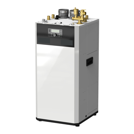
Page 7: Names Of Components
The FT Series Floor Standing, Combination Boiler Page 7 The FT Series Floor Standing, Combination Boiler Page 7 The FT Series Floor Standing, Combination Boiler Page 7 Names of Components Names of Components Names of Components Name of Component Pressure Relief Valve... -
Page 8: Product Flow Paths And Characteristics
Page 8 Names of Components 2.5.1 Central Heating flow. Combination Boiler Heating Mode. Water in the heating system flows through the low loss header (LLH); boiler pump heats water in the boiler and is circulated through LLH. System pump or individual zone pumps are required to pull heated water from CH supply connection and return water to CH return connection. -
Page 9: Section 3 Safety Regulations
The FT Series Floor Standing, Combination Boiler Page 9 SECTION 3 Safety Regulations Safety Symbols WARNING WARNING To avoid product damage, personal injury, or even FOR YOUR SAFETY READ BEFORE possible death, carefully read, understand, and OPERATING follow all the instructions in the Installation and... -
Page 10: Safety Precautions And Proper Use
Page 10 Safety Precautions and Proper Use damaging condition that might affect the operation of the unit. Boiler must be checked by a qualified technician before resuming operation. DO NOT use this Boiler if any part has been under water. Immediately call a qualified technician for inspecting the Boiler and replacing any part of the DANGER control system and gas control which have been... - Page 11 The FT Series Floor Standing, Combination Boiler Page 11 2. Caution for Ventilation Before Operation Make sure that there is sufficient inflow and outflow of air ventilation while using the unit. If the ventilation is improper, combustion quality may 1. Check the Gas Type (NG/LP) when using or deteriorate inside the appliance and cause shortened life moving the unit for the first time.
-
Page 12: Section 4 Installation
Page 12 SECTION 4 Installation Location and Clearances WARNING Installations must comply with The FT floor boiler must be installed on a level surface • All the local, state, provincial, and national codes, of sufficient strength and follow the clearances listed in laws, regulations and ordinances. -
Page 13: Flooring & Leveling
The FT Series Floor Standing, Combination Boiler Page 13 Flooring & Leveling WARNING Make sure that the floor and structure of the installation location are sufficient to support the full installed weight of the boiler, including water content of the heat exchanger and related piping. Failure to ensure the floor and structure of the installation location are structurally sound before installation of the boiler can result in structural failure, substantial property damage, severe personal injury, or death. -
Page 14: Combustion Air
Page 14 Combustion Air FT boilers must have provisions for combustion vertical or horizontal duct to the outdoors or spaces and ventilation air in accordance with the applicable that directly communicate with the outdoors and shall requirements for Combustion Air Supply and Ventilation have a minimum free area of 1 square inch per 3000 in the National Fuel Gas Code, ANSI Z223 1;... - Page 15 The FT Series Floor Standing, Combination Boiler Page 15 NOTICE AVIS The instructions for the installation of the venting Les instructions d'installation du système system shall specify that the horizontal portions of d'évacuation doivent préciser que les sections the venting system shall be supported to prevent horizontales doivent être supportées pour prévenir...
-
Page 16: Venting (Exhaust)
Page 16 Venting (Exhaust) WARNING NOTICE All venting must be installed according to this manual and any other applicable local codes, including but DO NOT COMMON VENT FT UNITS. FT not limited to, ANSI Z224.1/NFPA 54, CAN/CSA units are never permitted to share a vent with B149.1 and ULC-S636. -
Page 17: General Location Guideline
The FT Series Floor Standing, Combination Boiler Page 17 4 . Venting system components can only WARNING be mixed with alternate manufacturers’ Failure to vent this Boiler in accordance with these certified components when clearly listed instructions could cause a fire, resulting in severe in the manufacturers Installation Manual. -
Page 18: Locations For Vent Pipe Terminator
Page 18 Locations for Vent Pipe Terminator Canadian Installations 1 U.S. Installations 2 A = Clearance above grade, veranda, porch, deck, or balcony B = Clearance to window or door that may be ● 6 in (15 cm) for appliances ≤ 10,000 Btuh (3 kW) ●... -
Page 19: Venting Requirements In The Commonwealth Of Massachusetts
The FT Series Floor Standing, Combination Boiler Page 19 4.6.1 Venting Requirements in the Commonwealth of Massachusetts Inspection The state or local gas inspector of the In Massachusetts the following items are required if side-wall horizontally vented gas fueled appliance shall... -
Page 20: Common Vent Test
Page 20 Common Vent Test NOTE: This section does not describe a method for common venting FT units. It describes what must be done when an existing unit is removed from a common vent system. AVIS Au moment du retrait d'une chaudière existante, les mesures suivantes doivent être prises pour chaque appareil toujours raccordé... -
Page 21: Air Supply And Vent Connections
**When using 2" Combustion Air & Vent pipe, Propane Models are limited to 25 equivalent feet (7.5 M) of vent and 25 equivalent feet (7.5 M) of combus The FT Series Floor Standing, Combination Boiler Page 21 Air Supply and Vent Connections 4.8.1... -
Page 22: Indoor Combustion Air
Page 22 4.8.3 Indoor Combustion Air Read and follow section 4.3 Guidelines first. 1. Insert the termination end cap into the intake air duct. 2. Provide two openings to allow for circulation of combustion air as specified by ANSI Z224.1/NFPA 54. In Canada refer to CAN/CSA B-149.1 NOTE: The FT needs fresh air for safe operation and must be installed so there are provisions for... - Page 23 The FT Series Floor Standing, Combination Boiler Page 23 4.9 Vent / Air Pipe Termination (continued) Horizontal Vent Termination • Direct Vent - Sidewall Termination Exterior Wall Vent Screens are required 1” MIN Exhaust Elbow 12” MIN 12” MIN Exhaust...
- Page 24 Page 24 • Direct Vent - Optional Side wall Terminations Exterior Wall Concentric Vent Termination • Direct Vent - Optional Horizontal Exterior Wall Side Wall Kit and Vertical Concentric Vent (2” or 3”) NOTE: Concentric Vent Terminations cannot be Side Wall Kit less than 12”...
-
Page 25: Concentric Venting Systems
The FT Series Floor Standing, Combination Boiler Page 25 4.10.1 Concentric Venting Systems The following concentric venting systems and components are approved for use with the FT floor standing boilers: Table 6: Approved Heat-Fab SC series 3˝ x 5˝ stainless steel concentric venting components. -
Page 26: Installation Of A New Concentric Stainless Steel Venting System
Page 26 4.10.2 Installation of a Complete New Concentric 5) Properly support each horizontal and vertical Stainless Steel Venting System. section at least every 4 ft and at each elbow. Finish the vertical section by the installation of the SCO3VT For a vertical venting system, locate the boiler to affect Vertical Terminal Adapter on the last piece of vertical the shortest possible vent length run with the... -
Page 27: Existing Stainless Steel Venting
The FT Series Floor Standing, Combination Boiler Page 27 5) After completion of the venting system, review all changed, 45° offset fittings will be required to bring the joints of the venting installation and make sure that all centerline of the FT vent forward to align with the locking screws of the adjoining vent sections are all existing vent assembly. -
Page 28: Installation Of Duravent Pps
Page 28 4.10.4 New Installation of Duravent PPS in the following order: Concentric System 1) Insert a stainless steel to PP adaptor, (#4), into each of the FT boiler sockets and ensure that they The FT boiler has separate Combustion Air and Vent bottom out in the sockets. -
Page 29: Duravent Pps Concentric System To An Existing Heat-Fab Sc Venting System
The FT Series Floor Standing, Combination Boiler Page 29 Slide the 17.75” pipe down through the stainless steel 8) Additional concentric Duravent PP components can to PP adapter and connect it to the adapter on the FT boiler’s Vent connection. Ensure that item #3 bottoms be purchased from your local wholesaler. - Page 30 Page 30 venting system). If the existing venting system is a horizontal run, the slope of that system will need to be changed. As installed, that system required a downward slope of ¼” per foot toward the outside wall. The venting system for FT boiler requires a slope of 3/8”...
- Page 31 The FT Series Floor Standing, Combination Boiler Page 31 Stub-out Kit FT3002 ITEM QUANTITY PART Description NUMBER NUMBER 820014497 Concentric Adaptor 80/80 - 80/125 820001613 3˝ Diameter PP 12˝ Pipe Length 820019072 3˝ Diameter PP 17.750˝ Pipe Length 810004167 3˝ Diameter 3˝ PVC Male to 3˝ PP 810004128 3˝...
-
Page 32: Flexible Chimney Liner Venting
Page 32 Table 8: Approved components for use in 3˝ Vertical PP Flex venting. FT3003 PP to Heat-Fab Kit Part Number Description 3PPS-FLEX50 3˝ Diameter 50´ Flex PP 3PPS-FKC 3˝ Flex kit 3PPS-72C 3˝ 6´ PP Pipe 3PPS-E90C 3˝ PP elbow 3PPS-03PVCM-3PPF 3˝... -
Page 33: Gas Supply And Piping
The FT Series Floor Standing, Combination Boiler Page 33 4.11 Gas Supply and Piping WARNING: Gas piping should be supported by suitable hangers or Open flame can cause gas to ignite and result in floor stands, by the appliance. property damage, severe injury, or loss of life. - Page 34 Page 34 4.11 Gas Supply and Piping (cont) To facilitate any future maintenance, it is also The gas connection fitting is, 3/4” male NPT on recommended that an approved gas union fitting FTCF199 models. be installed in the supply line between the shut-off The supply line must be sized for the maximum valve and the 3/4˝...
- Page 35 The FT Series Floor Standing, Combination Boiler Page 35 Suggested Natural Gas (NG) Layout NOTE: Total gas supply capacity must not be less than the total demand capacity of the connected appliances. Gas Regulator (Supply Press 12˝ ) Suggested Propane Gas (LP) Layout...
-
Page 36: Gas Supply Pressure
Page 36 4.12 Gas Supply Pressure Refer to the illustration. Inlet Gas Pressure Port Gas Outlet / Manifold Pressure Port Offset Adjustment. Do Not Adjust without using a combustion analyzer to verify adjustment. Adjust ONLY when in MIN Fire and when using a combustion analyser. See Section 4.12 for step by step details. -
Page 37: Adjusting Combustion
The FT Series Floor Standing, Combination Boiler Page 37 4.13 Adjusting Combustion 1. Remove the front cover by opening the two clips ON. The unit will cycle down to MIN Fire. on the top of the boiler front cover - tilt forward and lift the cover off. -
Page 38: High Altitude Installations
Page 38 Adjusting Combustion (continued) Manifold Pressure Natural Gas Liquid Propane 2” VENT 3” VENT 2” VENT 3” VENT Max Fire -0.129” WC -0.314” WC -0.169” WC -0.173” WC FTCF199 Min Fire -0.015” WC -0.015” WC -0.015” WC -0.015” WC Table 11. -
Page 39: Natural Gas To Propane Conversion
The FT Series Floor Standing, Combination Boiler Page 39 4.15 Natural Gas to Propane Conversion The FT floor standing, condensing boiler is configured for Natural Gas (NG) from the factory. A Propane Conversion Kit is included with every FT. The gas conversion kit will show you how to convert your FT boiler to propane gas. - Page 40 Page 40 The FT Series, Wall Combi, Gas Conversion Kit Document 4388 4.15 Natural Gas to Propane Conversion (cont) Figure A Figure B Gas Valve Figure B Combustion Test Port Figure C ORIFICE FTCW140 PACKING FTCW199 Gas Valve Figure B...
- Page 41 The FT Series Floor Standing, Combination Boiler Page 41 4.15 Natural Gas to Propane Conversion (continued) Shown is a Model 199 Natural Gas with 3” Venting. LP Gas 2˝ Vent High Natural 3˝ Vent Fire Fire Table B Dip Switch Settings *Dip Switches #7 and #6 are Maximum and Minimum fire test Switches which are used only when setting up combustion (See Section 4.13)
- Page 42 CO should not exceed 200 ppm. Page 42 Natural Gas (NG) Propane Gas (LP) The FT Series, Wall Combi, Gas Conversion Kit Document 4388 value 2˝ VENT 3˝ VENT 2˝ VENT 3˝ VENT 4.15 Natural Gas to Propane Conversion (continued) MAX FIRE 8.5 - 10.5%...
-
Page 43: Plumbing Guidelines
The FT Series Floor Standing, Combination Boiler Page 43 4.16 Plumbing Guidelines 4.16.1 External Plumbing and Water CAUTION Connection Guidelines The built-in LLH allows direct piping of system - Ensure pipe material meets local codes and industry supply and return connections to their respective standards. -
Page 44: Dhw Piping Including Dhw Recirc Piping
Page 44 4.16.4 DHW Piping including DHW Recirculation Piping The FTCF199 boiler is capable of operating a DHW An anti-scald thermostatic mixing valve is included recirc pump along with receiving an input signal from with each FTCF199 and MUST be installed as out- either an DHW aquastat or 10 KOhm thermistor for lined below. - Page 45 The FT Series Floor Standing, Combination Boiler Page 45 Wiring for DHW recirculation loop pump controlled by the FTCF boiler RECIRCULATION LOOP WIRING DHW RECIRC PUMP (IF USED) DHW-R SENSOR (Surface Strap-on Sensor) (IF USED) (Factory Installed Jumper) L/ZC AC24V RECIRC.
-
Page 46: Zoning With Zone Valves
Page 46 Plumbing Guidelines (continued) 4.16.5 Zoning with zone valves - In a zone valve based system, there is one circulator pump and each heating zone has a zone valve which opens when the zone demands heat. - Each thermostat is wired directly to the corresponding zone valve. Contacts in the zone valves provide a call for heat to the zone relay panel when the valve is opened. - Page 47 The FT Series Floor Standing, Combination Boiler Page 47 Wiring of zone valve system with an optional high temp “on demand” zone with dedicated pump. SYSTEM 2 WIRING THERMOSTAT THERMOSTAT THERMOSTAT THERMOSTAT HI TEMP AUXILIARY 24 VAC ZONE INPUT MODE...
-
Page 48: Zoning With A Single Pump
Page 48 4.16.6 Zoning with a single pump 1) In a single zone system, an external zone pump is required and is wired directly back to the boiler to the system pump wiring terminals. 2) The zone thermostat (dry contract only) is wired back to the T-T connection on the low voltage terminal strip in the boiler. - Page 49 The FT Series Floor Standing, Combination Boiler Page 49 Wiring of a single pump system. SYSTEM 1 WIRING SYSTEM PUMP TSTAT OUTDOOR SENSOR (Factory Installed Jumper) L/ZC AC24V RECIRC. R 0-10V W MAIN POWER SYSTEM PUMP DHW RECIRC PUMP OUTPUT...
-
Page 50: Zoning With Multiple Pumps
Page 50 4.16.7 Zoning with multiple pumps 1) In a pump based system, each heating zone has its own circulator pump which run when the zone demands heat. 2) Each zone thermostat goes to a Pump Relay Panel which controls the pumps. The dry contact end switch of the relay panel connects back to the T-T terminals on the FT boiler. - Page 51 The FT Series Floor Standing, Combination Boiler Page 51 SYSTEM 3, WIRING Wiring of a multiple pump system. TSTATS ZONE 4 1234 PRIORITY HIGH OPEN LOW TEMP LOW TEMP TEMP FOUR ZONE SWITCHING RELAY WITH OPTIONAL PRIORITY POWER ZONE 1...
-
Page 52: Pressure Relief Valve
Page 52 4.18 Pressure Relief Valve External pressure relief valves must be installed. Ensure that the maximum BTU/H rating on the Observe the following. Failure to comply with the pressure relief valve is equal to or greater than the guidelines on installing the pressure relief valve and maximum input BTU/H rating of the combination boiler. -
Page 53: Disposal Of Condensate
The FT Series Floor Standing, Combination Boiler Page 53 • If desired, a discharge 1/4” or 3/8” can be routed by 4.18 Disposal of Condensate removing yellow cap from the top right rear corner • High efficiency gas condensing boilers create and routing the hose down to the condensate pump. -
Page 54: Dhw Flow Restrictors
Page 54 4.19 DHW Flow Restrictor Flow Restrictors are factory installed. Rated at 7.0 WARNING GPM for the model 199, this flow restrictor is white color. If the appliance has been filled and operational, then the gas, water and power must be To clean the flow restrictor and inlet water filter, completely shut off, and the unit must be drained perform the following steps:... -
Page 55: Electrical Wiring Connections
AC24V DHW RECIRC H-T/T OUTPUT SENSOR The FT Series Floor Standing, Combination Boiler Page 55 4.20 Electrical Wiring Connections Field Wiring: Top of terminals R 0-10V W R 0-10V W AC24V DHW RECIRC G L/ZC N T / T O / S... -
Page 56: Dip Switches
Page 56 4.20 Electrical Wiring Connections (continued) 4.21 Dip Switches Shown is a Model 199 Natural Gas with 3” Venting. LP Gas 2˝ Vent High Natural 3˝ Vent Fire Fire *Dip Switches #7 and #6 are Maximum and Minimum fire test Switches which are used only when setting up combustion (See Section 4.13). -
Page 57: Control Board, Electrical Diagram
The FT Series Floor Standing, Combination Boiler Page 57 4.22 Control Board, Electrical Diagram Control Board... -
Page 58: Ladder Diagram
Page 58 4.23 Ladder Diagram... -
Page 59: Electrical Connections (Table)
The FT Series Floor Standing, Combination Boiler Page 59 4.24 Electrical Connections, (table) Connector Description HT SELV #, Location, Type Label GROUND HT (120V~) Power Supply Line HT (120V~) Boiler Pump HT (120V~) Igniter HT (120V~) Heating/CP2 System Pump HT (120V~) - Page 60 Page 60 Electrical Connections , (table) (continued) Connector Description HT SELV #, Location, Type Label Flame Detect Sensor SELV (5V) OP.S Operating water temperature sensor SELV (5V) DH.S DHW outlet temperature sensor SELV (5V) System return temperature sensor SELV (5V) LWD1140-14 BG.S Venting (Exhaust) temperature sensor...
-
Page 61: Section 5 Control Display And Operation
The FT Series Floor Standing, Combination Boiler Page 61 53page SECTION 5 Control Display and Operation Control Dial and Buttons Status Light (constant green when when call for heat or hot water) The Control Display The Control Display has a Control Dial (E), 4 buttons (A, B, C, D), and a Liquid Crystal Display (with 72 back-lit segments). -
Page 62: Lcd Overview
Page 62 LCD Overview Anti-Freeze Storage Lock Communicating Central Mode Heating Heat Status and Installer Summer Modes Mode (warm weather Flame shutdown) Signal Outside Temp Mode or 0-10V Numeric Display Pump Domestic Hot Water Mode CH mode Central Heat mode icon can be adjusted Anti-freeze mode Anti-freeze mode icon Storage Heating mode... -
Page 63: Operating Mode
The FT Series Floor Standing, Combination Boiler Page 63 Operating Mode Operating Mode After the Power is turned on, and/or the Control Display is turned on , the Control Display 55page will go through a ‘Start Up’ checklist and briefly show a sequence of diagnostic codes before entering into the ‘Operating Mode. -
Page 64: Status Display Mode
56page Page 64 Status Display Mode 1. STATUS DISPLAY MODE (When button is pressed for 5 seconds When power to display panel is ON , status display will be activated) Digital Status Display Parameter Description Display Outdoor temperature (when --- is O:ot Current outdoor sensor temperature displayed, no outdoor sensor is connected) -
Page 65: Dhw Set Point Change Mode
The FT Series Floor Standing, Combination Boiler Page 65 57page DHW Set Point Change Mode DHW Set Point Change Modes The display shows the following information when changing water heating temperature set points. Changing between Celsius and Fahrenheit When the button D... -
Page 66: Set Point Change Mode
Page 66 58page CH Set Point Change Mode Changing between Celsius and Fahrenheit When the button D is pressed (for more than 5 seconds), temperature unit will toggle between °C and °F. Indicate Example Current Operating Temperature 110°F 58page Temperature sign Celsius or Fahrenheit letter °C or °F Display and Controller are communicating If flame detected... -
Page 67: Installer Parameters
59page The FT Series Floor Standing, Combination Boiler Page 67 Installer Parameters WARNING For low temperature heating applications, adjust P16 and possibly P17 to desired value(s). Proper high temperature protection might be required when the combination boiler transitions from DHW production to low temperature heating. - Page 68 Page 68 5.8 Installer Parameters (continued) Index Default Parameter Description 1: EH Error History History fault code (E0~E9) 2: cE Clear Error History Clearing of error History buffer 3: In System initialize System initialize to default 4: Fu Flow unit gallon / liter 5: St Heat storage function...
- Page 69 The FT Series Floor Standing, Combination Boiler Page 69 Index Default Parameter Description CH System Pump and This function sets the time to run Boiler pump to purge air from the DHW Indirect Pump Test AP:cP system. Range: 1 – 30 minutes...
-
Page 70: Outdoor Reset Adjustment
Page 70 Outdoor Reset Adjustment Outdoor Reset varies the control set point based on the outdoor temperature. The reset function works as shown in Figure ‘CH Outdoor Reset’. When the outdoor air temperature reaches 6:OH “high outdoor temperature set point”, the control point setting is adjusted to 17:cL “low boiler temperature set point”. -
Page 71: Error Mode
The FT Series Floor Standing, Combination Boiler Page 71 5.11 Error Mode 62page Flashing Indicate Example Error ‘ Er : ’ will flash Er:11 Error Code Er:11 Display and Controller are communicating NOTE: When communication between the Control Display and the main controller is lost, the will not be displayed. -
Page 72: Section 6 Error Codes 6.1 Error Code Tables
Page 72 SECTION 6 Error Codes Error Code Tables Error Error Code Recover Possible Remedies Code Description methods Press the Power button to clear the Error Code. If Error happens again: 1. Monitor the gas pressure to the appliance while in operation. Ensure pressure is between 3.5” to 10.5” WC (Nat. - Page 73 The FT Series Floor Standing, Combination Boiler Page 73 SECTION 6. Error Codes (continued) Error Error Code Recover Possible Remedies Code Description methods DHW outlet This Error Code will go away when CH temperature decreases. If Error happens again: sensor fault 1.
- Page 74 Page 74 Error Error Code Recover Possible Remedies Code Description methods This Error Code will go away when the condition is remedied. If Error happens again: MCU self 1. Turn power OFF and ON at the main power switch internal to the appliance. Soft Lock diagnostics fault 2.
-
Page 75: Fault Tree Analysis
The FT Series Floor Standing, Combination Boiler Page 75 Fault Tree Analysis 1. Flame detection... - Page 76 Page 76 6.2 Fault Tree Analysis (cont) 2. Gas Detection 3. ‘Storage’, ‘DHW’, ‘OP’, ‘CH overheat’, ‘Exhaust heat’ Sensor detects Error code contents DHW NTC open or short OP NTC open or short Exhaust NTC open or short...
-
Page 77: Section 7 Trouble Shooting Diagnostics
The FT Series Floor Standing, Combination Boiler Page 77 SECTION 7 Trouble Shooting Diagnostics Question Answer Make sure that the ON/OFF button on the Control Panel has been turned ON. If the monitor on the Control Panel is blank, make sure the power cord is plugged and 4A fuses on the main controller in the units are good. -
Page 78: Suggested Corrective Actions
Page 78 Suggested Corrective Actions This controller is able to record information about the boiler’s condition at the time of the five previous faults or errors. Refer to the Section ‘5.10 Error Mode’ of this manual. Display Condition Diagnostic Corrective Action(s) Check wiring for short Correct wiring per wiring diagram circuit or incorrect... - Page 79 The FT Series Floor Standing, Combination Boiler Page 79 7.2 Suggested Corrective Actions (continued) Fault Condition Diagnostic Corrective Action(s) Check all the temperature readings of the boiler on the DIAGNOSTICS - Occurs when TEMPERATURES menu to determine if any a temperature...
- Page 80 Page 80 this page intentionally left blank.
-
Page 81: Section 8 Maintenance
The FT Series Floor Standing, Combination Boiler Page 81 SECTION 8 Maintenance - Check the power source. Annual startup & Make sure that the power cord is correctly connected. general maintenance The main power line is connected to the manual switch box inside a combination boiler. - Page 82 Page 82 - Check the air vent If the air vent valve seems to work freely without seat. If the valve continues to weep, contact your leaking, close cap A fully. qualified service technician for inspecting the valve Loosen cap “A” one turn to allow vent to operate. and system.
-
Page 83: Flushing The Combination Boiler
The FT Series Floor Standing, Combination Boiler Page 83 Flushing the Combination Boiler Flushing the DHW Heat Exchanger is a complicated procedure that should only be done by an authorized technician or licensed professional. Keep in mind that improper maintenance can void your warranty. -
Page 84: Draining And Cleaning
Page 84 Draining and Cleaning The cold water inlet filter. Flow Restrictor FTCF199 Disconnect electrical power to the combination boiler. Close the external manual gas shut-off valve near the appliance. Remove top left access panel. Have a few towels handy to mop up any water. Close water supply valve on the inlet to the appliance. -
Page 85: Section 9 Installation Check
The FT Series Floor Standing, Combination Boiler Page 85 SECTION 9 Installation Check Freeze Protection (continued) Quick View WARNING Do NOT use automotive antifreeze or Before Installing ethylene glycol. Use only inhibited propylene - Make sure that there is enough space for installing... -
Page 86: Final Check Lists
Page 86 Final Check Lists Final check : Connecting the power supply Final check: Installation Conditions. • Please check that the power is 120V AC. • Is the Boiler placed level on a floor with sufficient • Have you checked the polarity of the electrical strength? •... - Page 87 The FT Series Floor Standing, Combination Boiler Page 87...
-
Page 88: Section 10 Parts List And Illustrations
Page 88 SECTION 10 Parts List and Illustrations FTCF199 Casing Assembly... - Page 89 The FT Series Floor Standing, Combination Boiler Page 89 FTCF199 Casing Parts Concentric Plug Bracket (110V) FT3029 Description Part Number Air Intake Collar Ass’y FT3010 Heat Exchanger Sub Bracket FT3030 (filter type) PCB Control Sub Bracket FT3031 Stainless Band(Ø100) FT1603...
- Page 90 Page 90 FTCF199 Tank and Water Pipe Assembly B-10 52-2 O-20 52-3 O-16 52-4 O-20 52-1 51-1 O-20 B-10 B-10 O-16 52-2 50-1 O-18 49-1 B-10 38-1 40-1 O-16 B-10 48-1 B-10 47-1 O-20 37-1 O-24 O-18 O-18 O-24 46-1 43-1 34-1 42-1...
- Page 91 The FT Series Floor Standing, Combination Boiler Page 91 FTCF199 Tank and Water Pipe Parts Description Part Number Description Part Number 43-1 DHW Outlet Pipe DHW Water Tank Ass’y FT3046 O-18 O-Ring P18 FT1687 Internal Circulation Pipe 2 Ass’y FT3047...
- Page 92 Page 92 FTCF199 Heat Exchanger and Tank Assembly 54-2 B-11 54-1 B-12 59-1 59-2 59-3 B-13 54-3 B-10 56-1 56-2 O-22 56-3 B-15 56-4 B-14 56-4a 60-2 56-7 56-4b 56-4c 60-1 56-8 56-9 60-3...
- Page 93 The FT Series Floor Standing, Combination Boiler Page 93 FTCF199 Heat Exchanger and Tank Parts Description Part Number Exhaust Duct Ass’y FT3090 54-1 Exhaust Duct 54-2 Exhaust Overheat Sensor FT1307 54-3 Exhaust Duct Packing (Lower) FT2036 3/8” Packing FT3062 B-11 M4 x 9MM Hex Head Screw (coarse thread) Heat Exchanger Ass’y...
- Page 94 Page 94 FTCF199 Fan and Gas Valve Assembly...
- Page 95 The FT Series Floor Standing, Combination Boiler Page 95 FTCF199 Fan and Gas Valve Parts Description Part Number Fan Guide Ass’y FT2087 61-1 Fan Guide 61-2 Fan Rubber Packing #2 FT2020 61-3 Damper Body Ass’y FT2044 61-4 Fan Guide Packing FT1772 Fan Ass’y...
- Page 96 Page 96 FTCF199 Accessory Items Description Part Number Pressure Relief Valve FT1500 Air Vent FT3117 Brass Adaptor FT3118 3/4” Brass Plug FT3119 Recirculation brass plug FT3120 Outdoor Temp. Sensor FT1501 Mixing Valve V20331 Bird Screens 3” (Qty 2) FT1730 Spare Parts Kit FT3121 Condensate Hose ST1070...
- Page 97 The FT Series Floor Standing, Combination Boiler Page 97 FTCF199...
- Page 98 Page 98 FTCF199...
- Page 99 The FT Series Floor Standing, Combination Boiler Page 99 FTCF199...
- Page 100 The FT Series Wall Mounted, Combination Boiler Notes: For Product and Service VIDEOS Dimensions and specifications subject to change without notice in accordance with our policy of continuous product improvement. 800.900.9276 • Fax 800.559.1583 Customer Service and Product Support: Industrial Way, Rochester, NH, USA 03867...
Need help?
Do you have a question about the FT Series and is the answer not in the manual?
Questions and answers