Laars FT Series Instructions Manual
Floor standing and wall-mounted modulating condensing gas heating only boilers
Hide thumbs
Also See for FT Series:
- User manual ,
- Installation and operation instructions manual (100 pages) ,
- Installation and operation instruction manual (100 pages)
Table of Contents
Advertisement
Cascade Instructions
FOR YOUR SAFETY: This product must be installed and serviced by a professional service technician,
qualified in hot water boiler and heater installation and maintenance. Improper installation and/or operation
could create carbon monoxide gas in flue gases which could cause serious injury, property damage, or
death. Improper installation and/or operation will void the warranty.
If the information in this manual is not
followed exactly, a fire or explosion may
result causing property damage, personal
injury or loss of life.
Do not store or use gasoline or other
flammable vapors and liquids in the vicinity of
this or any other appliance.
WHAT TO DO IF YOU SMELL GAS
• Do not try to light any appliance.
• Do not touch any electrical switch; do not
use any phone in your building.
• Immediately call your gas supplier from a
nearby phone. Follow the gas supplier's
instructions.
• If you cannot reach your gas supplier, call
the fire department.
Installation and service must be performed
by a qualified installer, service agency, or gas
supplier.
WARNING
Cascading the
FT
SERIES
Floor Standing and Wall-Mounted
Modulating Condensing Gas
Heating Only Boilers
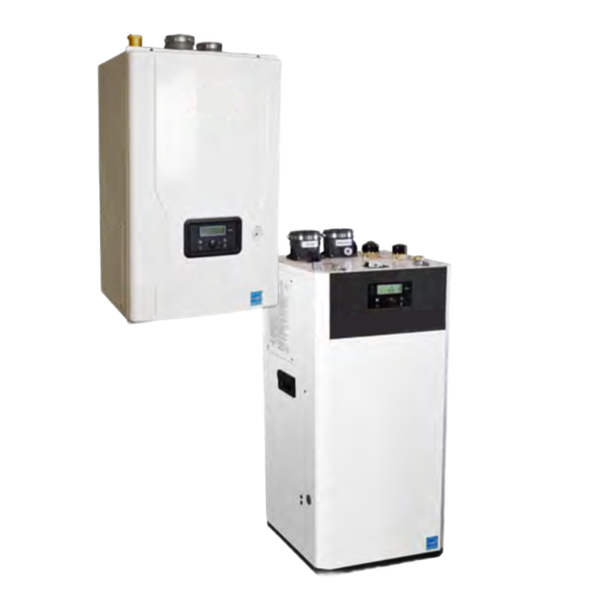
Floor Models: B/LFTHF199
Wall-Mounted Models: B/MFTHW 100, 140, 199
•
Natural Gas (NG)
Factory Configuration
Propane Gas (LP)
•
Field-Convertible
Assurez-vous de bien suivres les instructions
données dans cette notice pour réduire au
minimum le risque d'incendie ou d'explosion
ou pour éviter tout dommage matériel, toute
blessure ou la mort.
Ne pas entreposer ni utiliser d'essence ou ni
d'autres vapeurs ou liquides inflammables dans
le à proximité de cet appareil ou de tout autre
appareil.
QUE FAIRE SI VOUS SENTEZ UNE ODEUR DE
• Ne pas tenter d'allumer d'appareils.
• Ne touchez à aucun interrupteur. Ne pas vous servir
des téléphones dans le bâtiment où vous vous
trovez.
• Appelez immédiatement votre fournisseur de
gaz depuis un voisin. Suivez les instructions
du fournisseur.
• Si vous ne pouvez rejoindre le fournisseur de
gaz, appelez le sservice des incendies.
L'installation et l'entretien doivent être assurés par
un installateur ou un service d'entretien qualifié
ou par le fournisseur de gaz.
Document 1349C
AVERTISSEMENT
GAZ:
Advertisement
Table of Contents

Subscribe to Our Youtube Channel
Related Manuals for Laars FT Series


Summary of Contents for Laars FT Series
- Page 1 Cascade Instructions Document 1349C Cascading the SERIES Floor Standing and Wall-Mounted Modulating Condensing Gas Heating Only Boilers Floor Models: B/LFTHF199 Wall-Mounted Models: B/MFTHW 100, 140, 199 • Natural Gas (NG) Factory Configuration Propane Gas (LP) • Field-Convertible FOR YOUR SAFETY: This product must be installed and serviced by a professional service technician, qualified in hot water boiler and heater installation and maintenance.
-
Page 2: Table Of Contents
Page 2 Table of Contents SECTION 1 General Information..........3 1.A General Plumbing Connection Guidelines ......... 3 1.B Pipe Sizing for system and common supply & return headers in Cascade Systems ........3 1.C Product Flow Paths and Characteristics ........4 1.C.1 Floor Standing CH Circulation .......... -
Page 3: Section 1 General Information
Multiple FT Series boilers can be connected via a cascade communication cable to create a bank of boilers that work in tandem. Up to 20 boilers can be controlled by a “Leader” FT Series boiler with the others acting as “Followers”. All cascaded boilers must be the same model and size. -
Page 4: C Product Flow Paths And Characteristics
Page 4 1.C Product Flow Paths and Characteristics 1.C.1 Floor Standing CH Circulation Combustion Air Vent The floor standing models have a built in low loss header. The boiler circulation pump circulates the CH water CH Return GAS INPUT CH Supply in the boilers contained loop from heat exchanger to the low loss header (LLH) and back. -
Page 5: Wall-Mounted Ch Circulation
Cascading the FT Series ‘Heating Only’ Boiler Page 5 Combustion Air Vent Combustion Air Vent 1.C.2 Wall-Mounted CH Circulation The wall-mounted models do NOT have a built-in low loss header. The boiler circulation pump circulates the CH water out the common header up to 15’... -
Page 6: E Miscellaneous Wiring
Page 6 Miscellaneous Wiring Figure 5. Taco LTR0243T-1 -OR- SAFGard 1100 External LWCO... - Page 7 Cascading the FT Series ‘Heating Only’ Boiler Page 7 Figure 6. SAFGard 500 External LWCO Figure 7. SAFGard 550 External LWCO...
-
Page 8: Section 2 Piping And Wiring Diagrams
Page 8 SECTION 2 Piping and Wiring Diagrams 2.A Cascade FT Floor Heating Only Boilers Piping and Wiring Diagrams Figure 8. Two FT floor heating only models, cascaded reverse return with zone valves. - Page 9 Cascading the FT Series ‘Heating Only’ Boiler Page 9 Figure 9. Wiring diagram for cascaded reverse return with zone valves.
- Page 10 Page 10 Cascade FT Floor Heating Only Boilers Piping and Wiring Diagrams (continued) Figure 10. Two FT floor heating only models, cascaded reverse return with zone pumps.
- Page 11 Cascading the FT Series ‘Heating Only’ Boiler Page 11 Figure 11. Wiring diagram for cascaded reverse return with zone pumps.
- Page 12 Page 12 Cascade FT Floor Heating Only Boilers Piping and Wiring Diagrams (continued) Figure 12. Two FT floor heating only models, cascaded reverse return with pumps and indirect.
- Page 13 Cascading the FT Series ‘Heating Only’ Boiler Page 13 Figure 13. Wiring diagram for cascaded reverse return with system pumps and indirect.
- Page 14 Page 14 Cascade FT Floor Heating Only Boilers Piping and Wiring Diagrams (continued) Figure 14. Two FT floor heating only models, cascaded reverse return with low temp zones and air handlers.
- Page 15 Cascading the FT Series ‘Heating Only’ Boiler Page 15 Figure 15. Wiring diagram for cascaded reverse return with low temp zones and air handlers.
- Page 16 Page 16 Cascade FT Floor Heating Only Boilers Piping and Wiring Diagrams (continued) Figure 16. Three FT floor heating only models, cascaded reverse return with zone pumps and indirect.
- Page 17 Cascading the FT Series ‘Heating Only’ Boiler Page 17 Figure 17. Wiring diagram for cascaded reverse return with zone pumps and indirect.
-
Page 18: B Cascade Ft Wall-Mounted Heating Only Boilers Piping
Page 18 Cascade FT Wall-Mounted Expansion tank Heating only Check valve Indirect DHW Tank Boilers Piping (Diaphragm type) Pressure relief valve Air separator Circulation pump Mixing Valve Isolation valve Air Separator Purge 2-way valve Pressure Reducing Valve Zone Valve Cascade System Make Up Water Actuators Sensor... - Page 19 Cascading the FT Series ‘Heating Only’ Boiler Page 19 Leader Follower NOTE: These drawings are meant to show system piping concept only. Installer is responsible for all equipment and detailing required by local codes. 12" NOTE: The cascading communications cable is 60"...
- Page 20 Page 20 Cascade FT Wall-Mounted, Heating Only Boilers Piping Diagrams (continued) Expansion tank Check valve Indirect DHW Tank (Diaphragm type) Circulation pump Pressure relief valve Air separator Mixing Valve Isolation valve Air Separator Purge 2-way valve Pressure Reducing Valve Zone Valve Cascade System Make Up Water Actuators...
- Page 21 Cascading the FT Series ‘Heating Only’ Boiler Page 21 Cascade System - System Application & DHW Tank NOTE: DHW is a boiler dedicated load. The DHW sensor or aquastat must be connected to the Boiler dedicated to Domestic Hot water.
-
Page 22: Section 3 Cascade Communications
Notes: Perform start-up and combustion calibration of individual FT boilers BEFORE configuring the cascade system. Refer to Section 4 of the FT Series Heating Only Installation and Operation Instructions for details. A system sensor must be connected to the leader boiler in order to provide feedback for set point temperature reference and therefore properly control the bank of cascaded boilers. - Page 23 Cascading the FT Series ‘Heating Only’ Boiler Page 23 Leader Control Board Follower Control Board First Male Ending Connector. Resistor Wrap it up neatly and wire-tie it. It does not need a cap or an end. Last Female Connector. Shown are the control boards of the FT Plug the included ‘Ending Resistor’...
- Page 24 Knock Outs Connection Pin Terminal Blocks FT1861 : FT Series Cascade Communication Cables. Install per local codes and requirements. Figure 24. Using the available ‘Knock Outs’. NOTES: The cascading communications cable is 60" long. Routing for the FT Floor models can be via the side floor plastic knock-outs provided.
- Page 25 Heat. Reference the FT Series Wall-Mounted or Floor Standing Heating Only Installation and Operation Manual (Doc# 1483 or Doc# 1510) to set the Leader’s boiler temperature set point based on an outdoor sensor, 0-10 Volt signal or a fixed temperature setpoint.
-
Page 26: Section 4 The Control Display
The Control Display has a Control Dial (E), 4 buttons (A, B, C, D), and a Liquid Crystal Display (with 72 back-lit segments). Section 3 will show you only a few of the functions of the FT Series. For all functions, please review the FT Series Install and Instruction Manual. Doc 1342. -
Page 27: B The Lcd
Cascading the FT Series ‘Heating Only’ Boiler Page 27 4.B The LCD The LCD features a backlit lamp that will illuminate when a user presses a button. The display will time out after approximately 2 minutes. Symbol Name Description Service Reminder mode... -
Page 28: Section 5 Cascade Programming
Page 28 SECTION 5 Cascade Programming AUTODESK 5.A Programming a Cascade System Before connecting the cascading cables to the boiler, there are 2 items that need to be programmed on all units. Start with the Lead Unit and then Repeat on all Following Units, make sure to power down each unit after completing steps 1 thru 6 below. -
Page 29: B The Cascade Ch Function For Set Point Operation
Cascading the FT Series ‘Heating Only’ Boiler Page 29 The Cascade CH Function for Set Point Operation (Applicable when not using an outdoor sensor.) Changing the CH Set-Point, button. The CH Icon and current press the C CH Setpoint will flash. Turn the E dial clockwise to increase, and counterclockwise to decrease CH setpoint, until desired temperature is reached. -
Page 30: C Outdoor Reset Operation
Page 30 Index Numbers Parameter Description When set, the appliance will operate to heat CH water when water temperature falls below a differential Set differential setting. Example: If set point is 180°F and differential is 17: bo temperature to turn burner “ON”... - Page 31 Domestic Hot Water Parameters Domestic Hot Water Parameters For a complete list of parameters, reference the FT Series Installation and Operation Manual 1342. For a complete list of error codes reference the Mascot FT Installation and Operation Manual 1342 Index...
-
Page 32: E Cascade System Error Codes
Cascading the FT Series ‘Heating Only’ Boiler 5.E Cascade System Error Codes For a complete list of error codes, reference the FT Series Installation and Operation Manual 1342. Er:30 NOTE: This error will only appear if the boiler is used in a cascaded system.
Need help?
Do you have a question about the FT Series and is the answer not in the manual?
Questions and answers