Laars FT Series Installation And Operation Instructions Manual
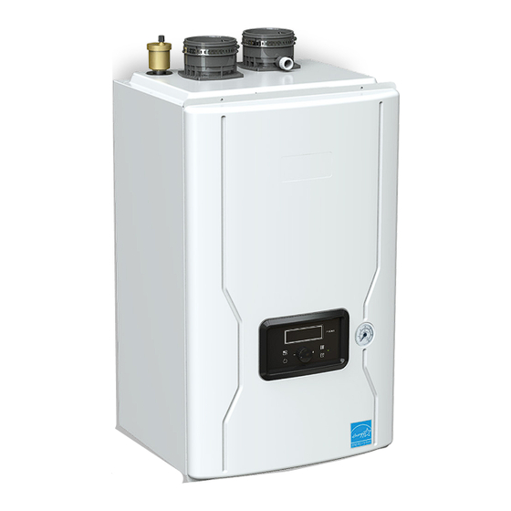
Wall-mounted, modulating gas, condensing, heating only, boiler
Hide thumbs
Also See for FT Series:
- User manual ,
- Installation and operation instructions manual (100 pages) ,
- Installation and operation instruction manual (100 pages)
Table of Contents
Advertisement
Installation and Operation Instructions
FOR YOUR SAFETY: This product must be installed and serviced by a professional service technician,
qualified in hot water boiler and heater installation and maintenance. Improper installation and/or operation
could create carbon monoxide gas in flue gases which could cause serious injury, property damage, or
death. Improper installation and/or operation will void the warranty.
If the information in this manual is not
followed exactly, a fire or explosion may
result causing property damage, personal
injury or loss of life.
Do not store or use gasoline or other
flammable vapors and liquids in the vicinity of
this or any other appliance.
WHAT TO DO IF YOU SMELL GAS
• Do not try to light any appliance.
• Do not touch any electrical switch; do not
use any phone in your building.
• Immediately call your gas supplier from a
nearby phone. Follow the gas supplier's
instructions.
• If you cannot reach your gas supplier, call
the fire department.
Installation and service must be performed
by a qualified installer, service agency, or gas
supplier.
Installation and Operation
Instructions for
THE
Wall-Mounted, Modulating
Gas, Condensing, Heating Only, Boiler
Model FTHW
WARNING
FT
SERIES
100,000 BTU/h
140,000 BTU/h
199,000 BTU/h
•
Natural Gas (NG) - Factory Configuration
•
Propane Gas (LP) - Field-Convertible
Assurez-vous de bien suivres les instructions
données dans cette notice pour réduire au
minimum le risque d'incendie ou d'explosion
ou pour éviter tout dommage matériel, toute
blessure ou la mort.
Ne pas entreposer ni utiliser d'essence ou ni
d'autres vapeurs ou liquides inflammables dans
le à proximité de cet appareil ou de tout autre
appareil.
QUE FAIRE SI VOUS SENTEZ UNE ODEUR DE
• Ne pas tenter d'allumer d'appareils.
• Ne touchez à aucun interrupteur. Ne pas vous servir
des téléphones dans le bâtiment où vous vous
trovez.
• Appelez immédiatement votre fournisseur de
gaz depuis un voisin. Suivez les instructions
du fournisseur.
• Si vous ne pouvez rejoindre le fournisseur de
gaz, appelez le sservice des incendies.
L'installation et l'entretien doivent être assurés par
un installateur ou un service d'entretien qualifié
ou par le fournisseur de gaz.
Document 1483A
AVERTISSEMENT
GAZ:
Advertisement
Table of Contents

Related Manuals for Laars FT Series


Summary of Contents for Laars FT Series
- Page 1 Installation and Operation Instructions Document 1483A Installation and Operation Instructions for SERIES Wall-Mounted, Modulating Gas, Condensing, Heating Only, Boiler Model FTHW 100,000 BTU/h 140,000 BTU/h 199,000 BTU/h • Natural Gas (NG) - Factory Configuration • Propane Gas (LP) - Field-Convertible FOR YOUR SAFETY: This product must be installed and serviced by a professional service technician, qualified in hot water boiler and heater installation and maintenance.
-
Page 2: Table Of Contents
SECTION 4 Installation CH Set Point Change Mode ......59 NOTE: For Cascading Installations, please refer to Status Display Mode ........60 document 1349 ‘Cascading the FT Series Boiler’, Installer Mode ..........61 available online. Storage Mode ..........64 Location and Clearances ....... 17 Outdoor Reset Adjustment ...... -
Page 3: Section 1 Introduction 1.1 About This Installation Manual
The FT Series Heating Only, Boiler Page 3 SECTION 1 Introduction For details on Combustion Air About this and Venting, See page 19 Installation Manual through to page 27 All installations must be made in This manual provides the accordance with information necessary for 1) American National Standard Z223.1/... -
Page 4: Included In The Box
Page 4 Included in the Box Item Description Wall Mounted Boiler FTHW (all sizes) Installation Instructions and User’s Manual Condensate Hose FT1894 Wall Mount Bracket 2 types of Wall Anchors Pressure Relief Valve (CH LINE 3/4˝ 30psi) Model: CASH ACME F-82 Mesh Screens 3”... -
Page 5: Section 2 Product Characteristics
SECTION 2 Product Characteristics Model Nomenclature (model number) The Model Nomenclature is shown on your Rating Plate and consists of a series of letters and numbers ( Nomenclature ) that further identifies the characteristics of your FT Series Boiler. FUEL ALTITUDE... -
Page 6: Specifications, 100Mbh, 140Mbh And 199Mbh
Page 6 Specifications, 100 MBH Model Name FTHW100 100,000 Btu/h Gas Input Rate 20,000 Btu/h Installation Indoor / Wall hung type Sealed Combustion Direct / Single Vent /Sidewall Flue System Vent Vent Run / Vent Material 2˝(50ft), 3˝(100ft) Schedule 40 CPVC, PP, PVC 0.181”... - Page 7 The FT Series Heating Only, Boiler Page 7 Specifications, 140 MBH Model Name FTHW140 140,000 Btu/h Gas Input Rate 14,000 Btu/h Installation Indoor / Wall hung type Sealed Combustion Direct / Single Vent /Sidewall Flue System Vent 2˝(50ft), 3˝(100ft) Schedule 40 CPVC, PP, PVC Vent Run / Vent Material 0.244”...
- Page 8 Page 8 Specifications, 199 MBH Model Name FTHW199 199,000 Btu/h Gas Input Rate 19,900 Btu/h Installation Indoor / Wall hung type Sealed Combustion Direct / Single Vent / Concentric Flue System Vent 2˝(50ft), 3˝(100ft) Schedule 40 CPVC, PP, PVC Vent Run / Vent Material 0.326˝...
-
Page 9: Dimensions
The FT Series Heating Only, Boiler Page 9 Dimensions 100 / 140 FTHW Heating only boiler Description Diameter Air Intake Collar 3˝ Vent Pipe Collar 3˝ ¼˝ 'CH' Supply ¼˝ 'CH' Return Gas Inlet 3/4˝ Condensate Line 1/2˝... - Page 10 Page 10 2.3 Dimensions FTHW Heating only boiler 3/4” 3/4” 7/8” 1/4” 1/4” 2.0" BOTTOM VIEW TOP VIEW FRONT VIEW Description Diameter Air Intake Collar 3˝ Vent Pipe Collar 3˝ ¼˝ 'CH' Supply 9page (199) ¼˝ 'CH' Return Gas Inlet 3/4˝...
-
Page 11: Names Of Components
The FT Series Heating Only, Boiler Page 11 Names of Components 100 / 140 FTHW Heating only boiler 4 SCREWS To remove the cover, unthread the 4 phillips head screws. Keep the screws in a safe place for re-application of cover. - Page 12 Page 12 2.4 Names of Components (continued) FTHW Heating Only Boiler 15 16 Name of Component Name of Component Air Vent (air eliminator) CH Pressure Gauge Air Intake Collar ‘CH’ Return Adapter Gas Valve Condensate Adapter Gas Inlet Pipe 2 Condensate Trap Air / Gas Mixing Pipe CH Return Temperature Sensor...
-
Page 13: Product Flow Paths And Characteristics
The FT Series Heating Only, Boiler Page 13 Product Flow Paths and Characteristics Water in the heating pipe is used for space heating. Combustion Combustion Air Vent Vent Gas Supply Gas Input CH Supply CH Supply CH Return CH Return... -
Page 14: Safety Symbols
Page 14 SECTION 3 Safety Regulations Safety Symbols WARNING WARNING To avoid product damage, personal injury, or even FOR YOUR SAFETY READ BEFORE possible death, carefully read, understand, and OPERATING follow all the instructions in the Installation and Operation manual before installation, operation If you do not follow these instructions exactly, a and service the Boiler. - Page 15 The FT Series Heating Only, Boiler Page 15 damaging condition that might affect the operation of the unit. Boiler must be checked by a qualified technician before resuming operation. DO NOT use this Boiler if any part has been under water.
-
Page 16: Safety Precautions And Proper Use
Page 16 Safety Precautions and Proper Use 3. Open windows for ventilation. Before Operation 4. Call a qualified service technician for immediate repair. 1. Check the Gas Type (NG/LP) When using or moving the unit for the first time. Check if gas type matches 2. -
Page 17: Section 4 Installation
The FT Series Heating Only, Boiler Page 17 SECTION 4 Installation WARNING NOTE: For Cascading Installations, please refer to document 1349 ‘Cascading the FT Series Installations must comply with • All the local, state, provincial, and national codes, Boiler’, available online. laws, regulations and ordinances. -
Page 18: Wall Mount Bracket
Page 18 Wall Mount Bracket 3" to Top of Unit 4.2.1 The installation height and location Anchors for your FT depends on your installation scenario. With all clearances considered, and given adequate positioning for Concrete, air supply and venting, you will need to determine the best Wood, position to mount the Wall Mount Bracket. -
Page 19: Combustion Air
The FT Series Heating Only, Boiler Page 19 Combustion Air Method 2: FT boilers must have provisions for combustion One permanent opening, commencing and ventilation air in accordance with the applicable within 12” (300mm) of the top of the enclosure, shall requirements for Combustion Air Supply and Ventilation be permitted. - Page 20 Page 20 NOTICE AVIS The instructions for the installation of the venting Les instructions d'installation du système system shall specify that the horizontal portions of d'évacuation doivent préciser que les sections the venting system shall be supported to prevent horizontales doivent être supportées pour prévenir sagging;...
-
Page 21: Venting, Exhaust
Category I appliances. NOTICE WARNING For Cascading Installations, please refer to document 1349 ‘Cascading the FT Series Boiler’, Use of cellular core PVC (ASTM F891), cellular core available online. CPVC, or Radel® (polyphenolsulfone) used in non- metallic venting systems is prohibited. -
Page 22: General Location Guideline
Page 22 Venting, Exhaust (continued) All components used in the vent system must be from a certified manufacturer. WARNING 4 . Vent system components must not be mixed with alternate manufacturers certified Failure to vent this Boiler in accordance with these components and/or unlisted components. -
Page 23: Locations For Vent Pipe Terminator
The FT Series Heating Only, Boiler Page 23 Locations for Vent Pipe Terminator † A vent shall not terminate directly above a sidewalk or paved driveway that is located between two single family dwellings and serves both dwellings. ‡ Permitted only if veranda, porch, deck, or balcony is fully open on a minimum of two sides beneath the floor. -
Page 24: Venting Requirements In The Commonwealth Of Massachusetts
Page 24 4.6.1 Venting Requirements in the Commonwealth of Massachusetts b. In the event that the requirements of the In Massachusetts the following items are required if subdivision cannot be met at the time of completion the side-wall exhaust vent termination is less than of installation, the owner shall have a period of thirty seven (7) feet above finished grade in the area (30) days to comply with the above requirements,... - Page 25 The FT Series Heating Only, Boiler Page 25 NOTICE AVIS NE PAS ÉVENT COMMUNE FT UNITÉS. FT unités DO NOT COMMON VENT FT UNITS. FT units ne sont jamais autorisés à partager un évent are never permitted to share a vent with Catégorie I avec les appareils.
-
Page 26: Air Supply And Vent Connections
Page 26 Air Supply and Vent Connections 4.7.1 Vent / Air Pipe Lengths Use this table for Doc. 1483 2" Combustion Air & Vent Pipe 3" Combustion Air & Vent Pipe Min. Min. Min. Vent Max. Combustion Min. Vent Max. Combustion Combustion Air Combustion Pipe... -
Page 27: Indoor Combustion Air
The FT Series Heating Only, Boiler Page 27 4.7.3 Indoor Combustion Air Read and Follow Sections 4.3 Guidelines First. 1. Insert the termination end cap into the intake air duct. 2. Provide two openings to allow for circulation of combustion air as specified by ANSI Z224.1/NFPA 54. - Page 28 Page 28 4.8 Vent / Air Pipe Termination (continued) Horizontal Vent Termination • Direct Vent - Sidewall Termination Exterior Wall Vent Screens are required 1” MIN Exhaust Elbow 12” MIN 12” MIN Exhaust Apart Exhaust Screen NOTE: The Exhaust must Air Intake Screen NOTE: Must be 12”...
- Page 29 The FT Series Heating Only, Boiler Page 29 • Direct Vent - Optional Side wall Terminations Exterior Wall Concentric Vent Termination • Direct Vent - Optional Horizontal Exterior Wall Side Wall Kit and Vertical Concentric Vent (2” or 3”) NOTE: Concentric Vent Terminations cannot be...
-
Page 30: Gas Supply And Piping
Page 30 Gas Supply and Piping WARNING: Gas piping should be supported by suitable hangers or Open flame can cause gas to ignite and result in floor stands, not the appliance. property damage, severe injury, or loss of life. Review the following instructions before proceeding with the installation. - Page 31 The FT Series Heating Only, Boiler Page 31 Natural Gas Pipe Sizing (Maximum) Maximum capacity of pipe in cubic feet of gas per hour for gas pressures of 0.5psi or less and a pressure drop of 0.5 Inch water column. (Based of a 0.60 Specific gravity gas) For reference only.
- Page 32 Page 32 4.9 Gas Supply and Piping (continued) Propane Gas Pipe Sizing (Maximum) Intended use : Pipe Sizing Between Single-or Second-Stage (Low Pressure) Regulator and Appliance. For reference only. Referenced from gas pipe manufacturer specifications for actual delivery capacity. The DOE standard for Natural Gas is 1100 BTU/ft3.
- Page 33 The FT Series Heating Only, Boiler Page 33 To facilitate any future maintenance, it is also The gas connection fitting on the unit is 3 / 4 ˝ male recommended that an approved gas union fitting NPT. be installed in the supply line between the shut-off The supply line must be sized for the maximum valve and the 3 / 4 ˝...
- Page 34 Page 34 4.9 Gas Supply and Piping (continued) Suggested Natural Gas (NG) Layout NOTE: Total gas supply capacity must not be less than the total demand capacity of the connected appliances. Gas Regulator (Supply Press 12˝ ) Suggested Propane Gas (LP) Layout NOTE: Total gas supply capacity must not be less than the total demand capacity of the...
-
Page 35: Gas Supply Pressure
The FT Series Heating Only, Boiler Page 35 4.10 Gas Supply Pressure The minimum and maximum inlet gas line pressures must be Natural Gas LP Gas Maximum Pressure 10.5˝ WC Maximum Pressure 13.0” WC Minimum Pressure 3.5˝ WC Minimum Pressure 8.0”... -
Page 36: Gas Setup And Adjustment
Turn ON the GAS and WATER supply to the FT. CO 2 @ 0-2,000 ft altitude (Natural Gas). of the installation process. The FT Series, Heating Only, Gas Conversion Kit Document 4387 Turn ON the FT. Connect a manometer to the manifold pressure port. For dual port manometers, use the positive pressure side. -
Page 37: High Altitude Installations
The FT Series Heating Only, Boiler Page 37 4.12 High Altitude Installations. 2,000’ to 10,000’ The FT is shipped with a default factory setting for installation at an 37page altitude of 0 to 2000’ (approx). For maximum efficiencies at higher altitudes (2,000’... -
Page 38: Natural Gas To Propane Conversion
Page 38 The FT Series, Heating Only, Gas Conversion Kit Document 4387 37page 4.13 Natural Gas to Propane Conversion The FT Series, heating only, condensing boiler is confi gured for Natural Gas (NG) from the factory. A Natural Gas to Propane Conversion Kit is included with every FT. - Page 39 The FT Series Heating Only, Boiler Page 39 The FT Series, Heating Only, Gas Conversion Kit Document 4387 Using a Phillips screwdriver, remove the 4 screws on the front cover. See Figure A. COMBUSTION COMBUSTION VALVE TEST PORT TEST PORT...
- Page 40 Page 40 The FT Series, Heating Only, Gas Conversion Kit Document 4387 4.13 Natural Gas to Propane Conversion (continued) MIN Fire Normal Operation MAX Fire Normal Operation NG Natural LP Propane 3” Vent Size 2” Vent Size These 3 bottom switches must be set per unit SIZE.
- Page 41 The FT Series Heating Only, Boiler Page 41 The FT Series, Heating Only, Gas Conversion Kit Document 4387 Propane Gas (LP) Natural Gas (NG) value 2˝ VENT 3˝ VENT 2˝ VENT 3˝ VENT 9.5~11% 8.5~10.5% MFTHW 80/100 All sizes 120/140/175/199 (and all altitudes) 9~10.5 %...
-
Page 42: Plumbing Guidelines
Page 42 4.14 Plumbing Guidelines 4.14.1 External Plumbing and Water CAUTION Connection Guidelines Use at least the MINIMUM pipe size for the entire - Ensure pipe material meets local codes and boiler loop piping (connecting boiler to and from industry standards. the primary/secondary connection). -
Page 43: Zoning With Zone Valve
The FT Series Heating Only, Boiler Page 43 4.14.4 Zoning with zone valves - In a valve based system, there is one circulator pump at the boiler and each heating zone has a zone valve which opens when the zone demands it. -
Page 44: Zoning With Circulation Pumps
Page 44 4.14 Plumbing Guidelines (continued) 4.14.5 Zoning with circulation pumps SECONDARY LOOP - Each heating zone of a pump (SPACE HEATING) SECONDARY LOOP based system has its own (SPACE HEATING) circulator pump which runs when that zone demands it. SECONDARY LOOP Do not - Each zone thermostat goes to... -
Page 45: Indirect Water Heating
(SPACE HEATING) The FT Series Heating Only, Boiler Page 45 Do not exceed 12" SECONDARY LOOP Note Make-Up Water (SPACE HEATING) 4.14.6 Indirect Water Heating - Installer is responsible for all equipment and detailing required by local codes. Do not exceed - The minimum pipe size of CH piping should be 1 ¼˝... -
Page 46: Multiple Units Using Zones Pumps And An Indirect For Dhw
Page 46 4.14 Plumbing Guidelines (continued) 4.14.7 Multiple units using zones pumps and an indirect for DHW CASCADE SECONDARY LOOP SYSTEM (SPACE HEATING) SENSOR Expansion tank (Diaphragm-type) Do not exceed Automatic air vent 12" Make-Up Water Note Air separator Circulation pump Check valve 1 / 2 ”... -
Page 47: Pressure Relief Valve
The FT Series Heating Only, Boiler Page 47 4.15 Pressure Relief Valve External pressure relief valves must be installed. WARNING Observe the following. Failure to comply with the guidelines on installing the pressure relief valve and Do not operate this appliance before the pressure... -
Page 48: Disposal Of Condensate
Page 48 4.16 Disposal of Condensate High efficiency gas condensing Boilers create condensation when operating. Condensation has acidic (pH) of approximately 4-5. Condensate must be drained in accordance with all local regulations. Follow your local code with regards to the disposal of condensation. One of 3 disposal methods must be followed 1. -
Page 49: Electrical Wiring Connections
The FT Series Heating Only, Boiler Page 49 4.17 Electrical Wiring Connections WARNING Install wiring and electrically ground boiler in accordance with authority having jurisdiction or, in the absence of such requirements, follow the National Electrical Code, NFPA 70, and/or CSA C22.1 Electrical Code-Part 1 in Canada. -
Page 50: Dip Switches
Cutoff Circulator (Factory Jumper Installed) Thermostat or Pump Endswitch (14 Gauge Wire) (18 Gauge Wire) The FT Series, Heating Only, Gas Conversion Kit Document 4387 4.18 DIP Switches MIN Fire Normal Operation MAX Fire Normal Operation NG Natural LP Propane 3”... -
Page 51: Control Board, Electrical Diagram
Page 51 The FT Series Heating Only, Boiler 4.19 Control Board, Electrical Diagram Control Board... -
Page 52: Ladder Diagram
Page 52 4.20 Ladder Diagram... -
Page 53: Electrical Connections (Table)
The FT Series Heating Only, Boiler Page 53 4.21 Electrical Connections Connector Description HT SELV #, Location, Type Label CASE GROUND HT (120V~) Power Supply Line HT (120V~) Central Heating Pump HT (120V~) Ignitor HT (120V~) HEAT/CP2 CH Pump HT (120V~) - Page 54 Page 54 4.21 Electrical Connections (continued) Connector Description HT SELV #, Location, Type Label Flame Detect Sensor SELV (5V) OP.S Operating water temperature sensor SELV (5V) DH.S Exhaust temperature sensor SELV (5V) CH Return temperature sensor SELV (5V) LWD1140-14 DHW temperature sensor or BG.S Mechanical SELV (5V)
-
Page 55: Section 5 Control Display And Operation
The FT Series Heating Only, Boiler Page 55 55page SECTION 5 Control Display and Operation Control Dial and Buttons Status Light (constant green when operating normally) The Control Display The Control Display has a Control Dial (E), 4 buttons (A, B, C, D), and a Liquid Crystal Display (with 72 back-lit segments). -
Page 56: Lcd Overview
Page 56 LCD Overview Symbol Name Description Service Reminder mode Service Reminder mode indication Outside Temperature Mode Outside Temp setting indication Anti-freeze mode Anti-freeze mode indication Storage mode Storage mode indication Information mode Information mode indication Communication state Communication state indication Time setting mode Time /Dispaly/Install mode indication Fan operating mode... -
Page 57: Operating Mode
The FT Series Heating Only, Boiler Page 57 Operating Mode 57page Operating Mode After the Power is turned on, and/or the Control Display is turned on , the Control Display will go through a ‘Start Up’ checklist and briefly show a sequence of diagnostic codes before entering into the ‘Operating Mode. -
Page 58: Setting The Clock
57page Page 58 Setting the Clock The P-950EH Control Display does NOT have a daily timer or programmable thermostat. Setting the Clock Press and hold the ‘Clock button’ for about 5 seconds. Set the ‘Year’ by turning the dial . And then, press the dial to Save. -
Page 59: Set Point Change Mode
57page The FT Series Heating Only, Boiler Page 59 CH Set Point Change Mode CH Set point Change Mode To change CH Set point, press the C button. The CH Icon and current CH Set point will flash. Turn the E dial clockwise to increase, and counterclockwise to decrease CH set point, until desired temperature is reached. -
Page 60: Status Display Mode
Dial E to save and to exit the Status Information Menu. To go back to the Operation Screen Press button B. NOTE: For Cascading Installations, please refer to document 1349 ‘Cascading the FT Series Boiler’, available online. Digital Display Status Display Parameter Description... -
Page 61: Installer Mode
The FT Series Heating Only, Boiler Page 61 Installer Mode 61page These changes are to be made only by a qualified technician. WARNING For low temperature heating applications, adjust P6 to desired value. For cascade applications, adjust P31 to desired water temperature. - Page 62 Page 62 5.7 Installer Mode (continued) Index Parameter Description Numbers Sets the design supply water temperature based on the maximum outdoor design temperature. Minimum supply Minimum Supply 7: cL temperature must be set at least 9°F below the maximum temperature supply temperature.
- Page 63 Page 63 The FT Series Heating Only, Boiler Index Parameter Description Numbers Cascade Number Range: 0 (Master), 1(slave 1), …., 19(slave 19) 27: Cn Cascade Number “29: CP” has to be set with the total number of units in the cascade before “28: Cn”...
-
Page 64: Storage Mode
Page 64 Storage Mode 64page Storage Mode / Indirect Water Heater To change Storage Mode Temp, First turn OFF the power to the Control Display. Then Press and Hold Button B to get into the Installer Mode. 25:St Rota te Dial E until you find Tap Dial E to enter Storage Mode. -
Page 65: Outdoor Reset Adjustment
The FT Series Heating Only, Boiler Page 65 Outdoor Reset Adjustment Outdoor Reset varies the control set point based on the outdoor temperature. The reset function works as shown in Figure ‘CH Outdoor Reset’. When the outdoor air 4:OH temperature reaches “high outdoor temperature... -
Page 66: Error Mode
Page 66 66page 5.11 Error Mode The Control Display will show the following information when an Error is presented. Flashing Indicate Indicator Error ‘ Er : ’ sign Segment Error Code Er:11 If Communication state is activated NOTE: When communication between the Control Display and the main controller is lost, the will not be displayed. -
Page 67: Section 6 Error Codes
The FT Series Heating Only, Boiler Page 67 SECTION 6 Error Codes Error Code Table Error Error Code Recover Possible Remedies Code Description methods Press the Power button to clear the Error Code. If Error happens again: 1. Monitor the gas pressure to the appliance while in operation. Ensure pressure is between 3.5"... - Page 68 Page 68 Error Code Table (continued) Error Recover Error Code Description Possible Remedies Code methods This Error Code will go away when exhaust temperature decreases. If Error happens again: Venting (Exhaust) Sensor 1. Check Venting (exhaust) temperature sensor. Ensure connections are secure. Soft Lock Open or Short 2.
- Page 69 The FT Series Heating Only, Boiler Page 69 Error Recover Error Code Description Possible Remedies Code methods Register, Ram, Rom, I/O This Error Code will go away when the condition is remedied. Port, AD Abnormal, Important If Error happens again:...
-
Page 70: Fault Tree Analysis
Page 70 Fault Tree Analysis 6.2.1 1. Flame detection... - Page 71 The FT Series Heating Only, Boiler Page 71 6.2.2 2. Gas Detection 6.2.3 Sensor detects ‘Storage’, ‘DHW’, ‘OP’, ‘CH overheat’, ‘Exhaust heat’ Error code contents DHW NTC open or short OP NTC open or short Exhaust NTC open or short...
-
Page 72: Section 7 Trouble Shooting
Page 72 SECTION 7 Trouble Shooting Diagnostics Question Answer Make sure that the ON/OFF button on the Control Display has been turned ON. If the monitor on the Control Display is blank, make sure the power cord is plugged and 4A fuses on the main controller in the units are good. Burner does not ignite Make sure that there is water supplied to the unit. -
Page 73: Suggested Corrective Actions
The FT Series Heating Only, Boiler Page 73 Suggested Corrective Actions This controller is able to record information about the boiler’s condition at the time of the five previous faults or errors. Refer to the Section ‘5.10 Error Mode’ of this manual. - Page 74 Page 74 7.2 Suggested Corrective Actions (continued) Fault Condition Diagnostic Corrective Action(s) Check all the temperature readings of the boiler on the DIAGNOSTICS Occurs when a - TEMPERATURES menu to determine temperature if any sensors are currently displayed sensor has as SHORT or OPEN.
-
Page 75: Section 8 Maintenance
The FT Series Heating Only, Boiler Page 75 SECTION 8 Maintenance Annual Startup & General Maintenance Regular Maintenance - Check the power source. Make sure that the power cord is correctly connected. The main power line is connected to - This Manual should be placed in a safe and dry the manual switch box inside a Boiler. -
Page 76: Flushing The Boiler
Page 76 8.1 Annual Startup & General Maintenance (continued) - Check the air vent If the air vent valve seems to work freely without If water does not flow from the valve even though leaking, replace cap “A” by twisting all the way on. you have lifted the lever completely, the valve or Loosen cap “A”... -
Page 77: Freeze Protection
11. Reinsert the filter and ensure the filter cap is securely tightened. 12. Connect electrical power to the boiler. Freeze Protection FT Series Boilers are certified for indoor use only, and NOTICE are not design-certified for placement outdoors. Different glycol products may provide varying degrees Proper precautions for freeze protection are of protection. -
Page 78: Section 9 Installation Check
Page 78 SECTION 9 Installation Check Freeze Protection (continued) Quick View WARNING Before Installing Do NOT use automotive antifreeze or - Make sure that there is enough space for installing ethylene glycol. Use only inhibited propylene Water and gas line. glycol solutions which are specially Verify vent/air termination is located as required. -
Page 79: Final Check Lists
The FT Series Heating Only, Boiler Page 79 Final Check Lists Final check : Connecting the power supply • Please check that the power is 120V AC. Final check : Installation Conditions. • Have you checked the polarity of the electrical •... -
Page 80: Section 10 Parts
Page 80 10.1 100 MBH Casing Assembly SECTION 10 Parts... - Page 81 The FT Series Heating Only, Boiler Page 81 Casing Parts 100 MBH Part Description Number 3/8" Packing FT1060 Exhaust vent duct assembly FT2000 Stainless band (Ø100) FT1603 Packing FT1604 3 inch Exhaust vent duct FT2001 O-Ring P75 FT1609 O-Ring P7...
- Page 82 Page 82 Heat Exchanger Assembly 100 MBH...
- Page 83 The FT Series Heating Only, Boiler Page 83 Heat Exchanger Parts Heat Exchanger & Tank (New) 100 MBH Part Description Number Exhaust pipe assembly FT2O11 30-1 Exhaust pipe FT2094 30-2 EX-Adaptor FT1784 30-3 Exhaust overheat sensor FT1307 30-4 Exhaust pipe packing (lower)
- Page 84 Page 84 Blower Assembly 100 MBH...
- Page 85 The FT Series Heating Only, Boiler Page 85 Blower Parts Fan & Gas Valve (New) 100 MBH Part Description Number Fan guide assembly FT2101 50-1 Fan guide FT2018 50-2 Damper body assembly FT2019 50-3 Fan rubber packing #2 FT2020 50-4 Fan rubber packing(1.6t)
-
Page 86: Parts Lists & Illustrations (Model 140)
Page 86 10.2 140 MBH Casing Assembly... - Page 87 The FT Series Heating Only, Boiler Page 87 Casing Parts 140 MBH Casing (New) Part Description Number 3/8" Packing FT1060 Exhaust vent duct assembly FT2000 Stainless band (Ø100) FT1603 Packing FT1604 3 inch Exhaust vent duct FT2001 O-Ring P75 FT1609...
- Page 88 Page 88 Heat Exchanger Assembly 140 MBH...
- Page 89 The FT Series Heating Only, Boiler Page 89 Heat Exchanger & Tank (New) Heat Exchanger Parts 140 MBH Part Description Number Exhaust pipe assembly FT2011 30-1 Exhaust pipe FT2094 30-2 EX-Adaptor FT1784 30-3 Exhaust overheat sensor FT1307 30-4 Exhaust pipe packing (lower)
- Page 90 Page 90 Blower Assembly 140 MBH...
- Page 91 The FT Series Heating Only, Boiler Page 91 Blower Parts 140 MBH Fan & Gas Valve (New) Part Description Number Fan guide assembly FT2101 50-1 Fan guide FT2018 50-2 Damper body assembly FT2019 50-3 Fan rubber packing #2 FT2020 50-4 Fan rubber packing (1.6t)
-
Page 92: Parts Lists & Illustrations (Model 199)
Page 92 Casing Assembly 10.3 199 MBH... - Page 93 The FT Series Heating Only, Boiler Page 93 Casing Parts 199 MBH Casing (New) Part Description Number 3/8" Packing FT1060 Exhaust vent duct assembly FT2000 Stainless band (Ø100) FT1603 Packing FT1604 3 inch Exhaust vent duct FT2001 O-Ring P75 FT1609...
- Page 94 Page 94 Heat Exchanger Assembly (199 MBH)
- Page 95 The FT Series Heating Only, Boiler Page 95 Heat Exchanger & Tank (New) Heat Exchanger Parts (199 MBH) Part Description Number Exhaust pipe assembly FT2035 30-1 Exhaust pipe FT2125 30-2 EX-Adaptor FT1784 30-3 Exhaust overheat sensor FT1307 30-4 Exhaust pipe packing (lower)
- Page 96 Page 96 Blower Assembly (199 MBH)
- Page 97 The FT Series Heating Only, Boiler Page 97 Blower Parts (199 MBH) Fan & Gas Valve (New) Part Description Number Fan guide assembly FT2134 50-1 Fan guide FT2043 50-2 Damper body assembly FT2044 50-3 Fan rubber packing #2 FT2020 50-4...
- Page 98 Page 98 Notes:...
- Page 99 The FT Series Heating Only, Boiler Page 99 Notes:...
- Page 100 The FT Series Wall Mounted, Heating Only, Boiler Notes: For Product and Service VIDEOS Dimensions and specifications subject to change without notice in accordance with our policy of continuous product improvement. 800.900.9276 • Fax 800.559.1583 Customer Service and Product Support:...
Need help?
Do you have a question about the FT Series and is the answer not in the manual?
Questions and answers