Table of Contents
Advertisement
Quick Links
Advertisement
Table of Contents

Related Manuals for LumaSense technologies IMPAC IGAR 320


Summary of Contents for LumaSense technologies IMPAC IGAR 320
- Page 1 IMPAC Pyrometer IGAR 320...
- Page 2 LumaSense Technologies prohibits the duplication of any portion of this manual or the use thereof for any purpose other than the operation or maintenance of the equipment described in this manual, without the express written permission of LumaSense Technologies.
-
Page 3: Table Of Contents
Contents General Information ....................... 5 1.1 Information about the user manual ..............5 1.1.1 Legend ........................5 1.1.2 Terminology ......................5 1.2 Safety ........................5 1.3 Limit of Liability and Warranty ................5 1.4 Unpacking the Instrument ..................6 1.5 Service Request, Repair, or Support ..............6 1.6 Shipments to LumaSense for Repair .............. - Page 4 4.3 Transmittance τ ..................... 19 4.4 Response Time (t ) ....................19 4.5 Clear Peak Memory (t ) ..................19 CLEAR 4.5.1 Single and Double Storage Modes ............... 19 4.5.2 Clear Time Settings ....................20 4.6 Analog Output ....................... 20 4.7 Relative Signal Strength ..................
-
Page 5: General Information
LumaSense Technologies is not liable for any damages that arise from the use of any examples or processes mentioned in this manual or in case the content of this document should be incomplete or incorrect. -
Page 6: Unpacking The Instrument
The warranty is VOID if the instrument is disassembled, tampered with, altered, or otherwise damaged without prior written consent from LumaSense Technologies; or if considered by LumaSense Technologies to be abused or used in abnormal conditions. There are no user- serviceable components in the instrument. -
Page 7: Shipments To Lumasense For Repair
Email: eusupport@lumasenseinc.com 1.6 Shipments to LumaSense for Repair All RMA shipments of LumaSense Technologies instruments are to be prepaid and insured by way of United Parcel Service (UPS) or preferred choice. For overseas customers, ship units air- freight, priority one. - Page 8 To ensure consistent document formatting, this page was intentionally left blank. IGAR 320 Manual General Information • 8...
-
Page 9: Introduction
2 Introduction 2.1 Appropriate Use The IMPAC IGAR 320 pyrometer is a stationary, digital pyrometer for non-contact temperature measurement on metals, ceramics, graphite, semiconductors etc. in the range between 300 and 1300 °C. The pyrometer measures in 2-color mode (ratio principle) in which two adjacent wavelengths are used to calculate the temperature. - Page 10 Optics Sighting: Built-in LED targeting light and LEDs for intensity alignment Optics: Fixed optics a=300 mm or a=800 mm Distance Ratio: approx. 100 : 1 Environment Protection Class: IP 65 IEC 60529 (value in mated condition) Operating Position: Ambient Temperature: 0 to 65 °C at housing Storage Temperature: -20 to 80 °C...
-
Page 11: Dimensions
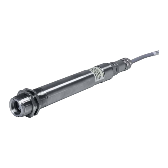
2.4 Dimensions All dimensions in mm 2.5 Physical User Interface 1 8-Pin Connector 2 Signal light for power supply 3 Intensity change indicators 2.6 Accessories (Optional) Numerous accessories guarantee easy installation of the pyrometer. The following overview shows a selection of suitable accessories. You can find the entire accessory program with all reference numbers in Chapter 8, Reference numbers. -
Page 12: Air Purge
2.6.3 Air Purge The air purge protects the lens from contamination of dust and moisture. It has to be supplied with dry and oil-free pressurized air and generates an air stream shaped like a cone. 2.6.4 90° Mirror The 90° mirror enables the capture of objects at an angle of 90° to the pyrometer axis. -
Page 13: Controls And Installation
3 Controls and Installation 3.1 Electrical Installation The pyrometer is powered by 24 V DC ± 25% (very well stabilized, ripple max. 50 mV). It is important to ensure correct polarity when connecting the device to the power supply. To meet the electromagnetic requirements (EMV), a shielded connecting cable must be used. LumaSense offers connecting cables, which are not part of the standard scope of delivery. -
Page 14: Connecting The Pyrometer To A Pc
3.1.2 Connecting the Pyrometer to a PC The pyrometer is equipped with an RS485 serial interface. With the RS485, long transmission distances can be realized and the transmission is, to a large extent, free of problems. The RS485 also allows several pyrometers to be connected in a bus system. If an RS485 connection is not available at the PC, it can be accomplished using the RS485 to USB connector. -
Page 15: Sighting
Connection of Additional Units Other instruments like an analog controller or printer can be connected to the display in a series as shown above (total load of resistance max. 500 Ohm). 3.2 Sighting 3.2.1 LED Targeting Light The IGAR 320 is equipped with a LED targeting light to assist with aligning the pyrometer to the measuring object. -
Page 16: Optics
3.3 Optics 3.3.1 Spot Sizes The IGAR 320 has fixed optics for 300 mm or 800 mm measuring distance. The table of spot sizes in relation to measuring distance shows examples of the pyrometer’s spot size M [mm] in relation to the measuring distance a [mm] (min. 90% of the radiation intensity). Increasing or decreasing the measuring distance will change the spot size. -
Page 17: Settings / Parameter Descriptions
4 Settings / Parameter Descriptions The pyrometer is equipped with a wide range of settings to adapt optimally to the required measuring conditions for correct temperature measurement. The digital PC interface allows you to exchange data with a PC either by using the supplied InfraWin software or by using the Universal Pyrometer Protocol (UPP) commands with your own communication program (see Chapter 7 for the UPP Data Format commands). -
Page 18: Temperature Errors Cause By Non-Graybodies
Note: Emissivity Slope K Settings: 0.600 to 2.000 in steps of 1/1000 (2-color mode). 4.2.1 Temperature Errors Cause by Non-Graybodies A graybody target has emissivity that is the same at each of the two wavelengths used for measurements and is constant throughout the temperature range. The ratio of the emissivities, ε1 / ε2= 1 and stays constant regardless of the target temperature. -
Page 19: Transmittance Τ
4.3 Transmittance τ Transmittance is a parameter that can compensate for signal loss due to external windows etc. For example, if the emissivity of the material is 0.6 and the transmittance of an additional window is 0.9, then the product would be 0.54, which is well inside the allowed range. ε... -
Page 20: Clear Time Settings
Double Storage Double storage mode comes into effect when selecting one of the reset Mode: intervals. This mode utilizes two memories. With the first memory, the highest measured value is held and is deleted alternately in the time interval set (clear time). The other memory retains the maximum value throughout the next time interval. -
Page 21: Relative Signal Strength
4.7 Relative Signal Strength Relative signal strength stands for the product of emissivity, surface coverage, and transmission of the material between object and pyrometer. 4.8 “Dirty Window” Warning The IGAR 320 pyrometers are equipped with a warning level “dirty window” monitoring system. A correct temperature measurement might be impossible if the ratio pyrometer is working at a too low signal level. -
Page 22: Sub Range
4.11 Sub Range You have the opportunity to choose a sub range (minimum span 50 °C) within the basic measuring range of the pyrometer. This sub range corresponds to the analog output. Example: Range 300…1300 °C, Sub Range 500…600 °C. The sub range setting also affects the maximum value storage when the Clear Peak Memory is set to AUTO. - Page 23 Close below: The contact closes (switches to ground), if the temperature falls below the entered value in the “SP1“box. If the temperature exceeds that, value plus the hysteresis the contact opens (a hysteresis between 2 and 20°C can be set to avoid oscillating of the switch in the switch point).
- Page 24 To ensure consistent document formatting, this page was intentionally left blank. IGAR 320 Manual Settings / parameter descriptions • 24...
-
Page 25: Software Infrawin
5 Software InfraWin The operating and analyzing InfraWin software is included with delivery of the pyrometer. In addition to allowing you to make parameter adjustments, the InfraWin software also provides temperature indication, data logging, and measurement analysis features. A software description can be found in the program’s help menu. Click on the F1 button after loading InfraWin or click on the ? in the menu bar. - Page 26 To ensure consistent document formatting, this page was intentionally left blank. IGAR 320 Manual Software InfraWin • 26...
-
Page 27: Maintenance
6 Maintenance 6.1 Cleaning IGAR 320 window Because there are no moving parts in the IGAR 320, the only regular maintenance required is a periodic inspection of the front window for build-up of foreign particles, which, in time, can influence the energy received by the instrument. The IGAR 320 has a “Dirty Window” warning alarm feature that can measure the current window/optical path transmission and provide a contact closure alert when the window transmission falls below the user set point. - Page 28 • Spot Sizes: Ensure the IGAR 320 is using a proper focused distance and takes into account the spot size in relation to measuring distance. In the 1-color (mono) mode, the pyrometer can measure objects at any distance. However, the object has to be bigger than or at least as big as the spot size of the pyrometer in the measuring distance.
-
Page 29: Data Format Upp (Universal Pyrometer Protocol)
7 Data Format UPP (Universal Pyrometer Protocol) Software commands can be exchanged directly with the pyrometer through an interface using suitable communication software or by using the Test function located in the Pyrometer Parameters window of the InfraWin software package. The data exchange occurs in ASCII format with the following transmission parameters: The data format is: 8 data bits, 1 stop bit, even parity (8,1,e) no handshake;... - Page 30 Description Command Parameters Measuring value AAek Answer: SSSSSQQQQQ (one-channel and 2x5 decimal digits (in °C or °F, last digit is 1/10 °C or °F), ratio temperature) SSSSS = one-channel temperature QQQQQ=ratio temperature ε AAemXXXX ε Emissivity for one- XXXX = 0100 to 1000 =0.100 to 1.000 AAem channel temperature...
- Page 31 Description Command Parameters Measuring value AAms Answer: QQQQQ (88880=Overflow) 5 decimal digit (in °C or °F, last digit is 1/10 °C or °F) Limit switch SP1 AAslXXXX XXXX = set Limit switch, hex 4-digit, °C or °F Mode AAt1X X = 0 Limit switch Off Limit switch SP1 X = 1 Limit switch close above X = 2 Limit switch close below...
- Page 32 To ensure consistent document formatting, this page was intentionally left blank. IGAR 320 Manual Data format UPP • 32...
-
Page 33: Reference Numbers
8 Reference Numbers 8.1 Reference Numbers Instrument Temperature Range Reference Number a / mm IGAR 320, 300 to 1300 °C 3 903 600 IGAR 320, 300 to 1300 °C 3 903 610 Ordering note: A connection cable is not included in scope of delivery and has to be ordered separately. 8.2 Reference numbers accessories 3 820 320 Special connection cable with angled connector and additional targeting light push... - Page 34 3 852 290 Power supply NG DC for DIN rail mounting; 100 to 240 V AC ⇒ 24 V DC, 1 A 3 852 550 Power supply NG 2D for DIN rail mounting; 85 to 265 V AC ⇒ 24 V DC, 600 mA USB nano: Converter RS485 ⇔...
-
Page 35: Troubleshooting
9 Troubleshooting Symptom Probable Cause Comments No analog output even if the Reversed leads to IGAR 320 The IGAR 320 is diode display shows a temperature protected if power leads Reversed leads to other instruments in the above lower range limit are reversed current loop See section 3.1... - Page 36 Symptom Probable Cause Comments Temperature readings are too Incorrect slope adjustments See section 4.2 high The measurement is influenced by reflections Use mechanical of hot machine parts accessories to avoid the influence of the interfering radiation. If target emissivity is less than 1, reflections Block reflection paths to from nearby hot objects will influence readings see if readings drop to...
- Page 37 Symptom Probable Cause Comments Noisy readings (fast Improper grounding of cable shield and/or fluctuations) IGAR 320 housing Flame or reflections of flame may be entering the field of view Extremely dense steam, smoke, thick dust, personnel or moving machinery intermittently blocking 95% of optical path of IGAR 320 Non-uniform emissivity of large moving targets Slower response speed is...
- Page 38 To ensure consistent document formatting, this page was intentionally left blank. IGAR 320 Manual Troubleshooting • 38...
-
Page 39: Index
Index Accesories 11 Air Purge 12 Laboratory Calibration 27 Analog Output 20 Laser Targeting Light 16 Appropriate use 9 Legend 5 Liability 5 Baud Rate 22 Maintenance 27 Mounting 11 Calibration 27 Laboratory 27 On-Site 27 On-Site Calibration 27 Cleaning the front window 27 Optics 16 Clear Peak Memory 19 Clear Time Settings 20... - Page 40 Sub Range 22 Support 6 Technical Data 9 Transmittance 19 Transport 7 Troubleshooting 35 Unpacking the Instrument 6 UPP data format 29 Warranty 5 IGAR 320 Manual Index • 40...
Need help?
Do you have a question about the IMPAC IGAR 320 and is the answer not in the manual?
Questions and answers