Table of Contents
Advertisement
Quick Links
Advertisement
Table of Contents

Related Manuals for LumaSense technologies 5 Series


Summary of Contents for LumaSense technologies 5 Series
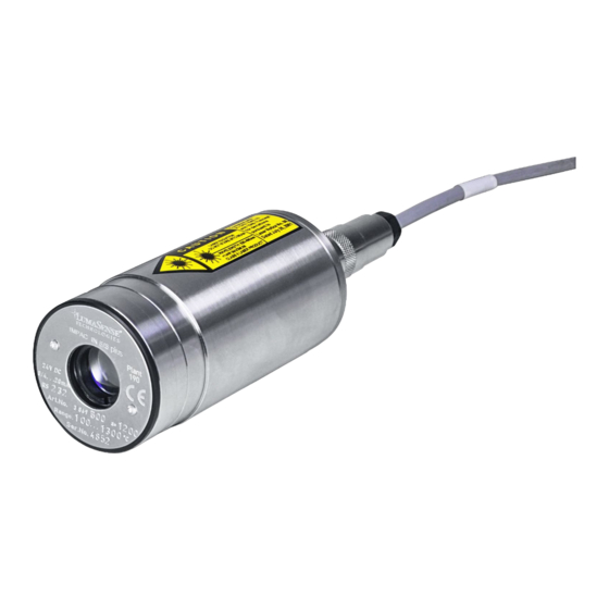
- Page 1 Series 5 IN 5/5 plus IMPAC Pyrometer...
- Page 2 LumaSense Technologies prohibits the duplication of any portion of this manual or the use thereof for any purpose other than the operation or maintenance of the equipment described in this manual, without the express written permission of LumaSense Technologies or Advanced Energy Industries, Inc.
-
Page 3: Table Of Contents
Contents General........................5 1.1 Information about the user manual ..............5 1.1.1 Legend ..................... 5 1.1.2 Terminology....................5 1.2 Safety ........................5 1.2.1 Laser targeting light .................. 6 1.2.2 Electrical connection .................. 6 1.3 Limit of liability and warranty ................6 1.4 Unpacking the Instrument .................. - Page 4 Settings / Parameter Descriptions ................21 5.1 Online- / offline mode (ONL/OFFL)..............21 5.2 Emissivity (EMI)....................21 5.3 Exposure time (t ) .................... 22 5.4 Analog output 0/4 to 20 mA................23 5.5 Maximum / minimum value storage ..............23 5.6 Subrange ......................
-
Page 5: General
1 General 1.1 Information about the user manual Congratulations on choosing the high quality and highly efficient IMPAC pyrometer. This manual provides important information about the instrument and can be used as a work of reference for installing, operating, and maintaining your IMPAC pyrometer. It is important that you carefully read the information contained in this manual and follow all safety procedures before you install or operate the instrument. -
Page 6: Laser Targeting Light
LumaSense Technologies is not liable for any damages that arise from the use of any examples or processes mentioned in this manual or in case the content of this document should be incomplete or incorrect. -
Page 7: Unpacking The Instrument
Email: eusupport@lumasenseinc.com 1.6 Shipments to LumaSense for Repair All RMA shipments of LumaSense Technologies instruments are to be prepaid and insured by way of United Parcel Service (UPS) or preferred choice. For overseas customers, ship units air- freight, priority one. -
Page 8: Transport, Packaging, Storage
Customers in North America All other customers should send RMA Shipments to: should send RMA Shipments to: Frankfurt, Germany Santa Clara, California LumaSense Technologies, Inc. LumaSense Technologies GmbH 3301 Leonard Court Kleyerstr. 90 Santa Clara, CA 95054 USA 60326 Frankfurt... -
Page 9: Introduction
2 Introduction 2.1 Appropriate use IN 5/5 plus: The IMPAC pyrometer IN 5/5 plus is a stationary pyrometer especially for non- contact temperature measurement of glass surfaces and quartz surfaces with temperature ranges between 100 and 2500 °C. IN 5/5-L plus: as IN 5/5 plus, with small spot size (temperature ranges between 200 and 2500 °C). - Page 10 Analog Output: 0 ... 20 mA or 4 ... 20 mA (linear), adjustable Maximum / minimum Built-in single and double storage. Clearing with clear time t clear value storage: (0.1 s; 0.25 s; 0.5 s; 1 s; 5 s; 25 s), external contact or via interface or also automatically with each new item to be measured Interface: RS232 or RS485 (addressable, half duplex), baud rate 1.2 up to 19.2 kBd,...
-
Page 11: Dimensions
Whichever value is greater. The instrument must be at a constant ambient temperature for a minimum of 15 minutes (30 min for IN 5/5-L plus for 200 ... 1300 °C @ T = 0 ... 15 or 30 ... 63 °C) and has to be connected to the power supply. Note: The determination of the technical data of this pyrometer is carried out in accordance with VDI/VDE directive IEC TS 62942-2, “Determination of the technical data for radiation thermometers”. -
Page 12: Accessories (Optional)
2.6 Accessories (Optional) Numerous accessories guarantee easy installation of the pyrometer. The following overview shows a selection of suitable accessories. You can find the entire accessory program with all reference numbers in Chapter 10, Reference numbers. Mounting: For easy mounting and aligning the pyrometer to the measured object an adjustable mounting angle is available. -
Page 13: Controls And Installation
3 Controls and Installation 3.1 Electrical Installation The series 5 pyrometers are powered by 24 V DC nominal (possible range: 18 to 30 V DC, ripple must be less than 0.5 V). When connecting the device to the power supply ensure correct polarity. -
Page 14: Connecting The Pyrometer To A Pc
3.1.2 Connecting the pyrometer to a PC The pyrometers are equipped with a serial interface RS232 or RS485 (switchable at the pyrometer). Standard on a PC is the RS232 interface. At this interface one pyrometer can be connected if the interface is set to RS232. Only short distances can be transmitted with RS232 and electromagnetic interferences can affect the transmission. -
Page 15: Connection Of Additional Analyzing Devices
3.1.5 Connection of additional analyzing devices Additional analyzing instruments, for example a LED digital display instrument only needs to be connected to a power supply and the analog outputs from the pyrometer. Another Instruments like a controller or printer can be connected to the display in series as shown above (total load of resistance max. -
Page 16: Thermal Alignment
3.2.2 Thermal alignment When measuring a hot object in front of a cooler background, it usually suffices to align the pyrometer to achieve the highest temperature reading. 3.3 Optics The pyrometers are equipped ex works with one of the following optics. These lenses are focusing to certain distances. - Page 17 IN 5/5-L plus Note: Please note that the optical profiles show nominal dimensions. The spot size diameter or the focal distance may be slightly different due to lens tolerances. Note: The InfraWin program includes a Spot size calculator that roughly estimates the unknown values.
- Page 18 To ensure consistent document formatting, this page was intentionally left blank. Controls and Installation • 18 IN 5/5 plus Operating Manual...
-
Page 19: Instrument Settings
4 Instrument Settings 4.1 Instrument settings Before using the pyrometer, some basic settings should be taken. The basic settings can be done at the pyrometer itself, some further settings can be done via interface and software InfraWin. Settings at the instrument: The basic settings are emissivity, exposure time, analog output. These settings can be adjusted at the pyrometer only in offline mode (see 5.1 Online- / offline mode (ONL/OFFL)). -
Page 20: Factory Settings
4.2 Factory settings Instrument settings: Emissivity (Emi) = 100% Exposure time (t ) = 0.08 s Analog output(4/0 mA) = 0... 20 mA Online- / offline mode (ONL/OFFL) = offline Interface settings: Emissivity (Emi) = 100% Exposure time (t ) = 0.08 s Analog output (4/0 mA) = 0... -
Page 21: Settings / Parameter Descriptions
5 Settings / Parameter Descriptions 5.1 Online- / offline mode (ONL/OFFL) Offline (OFFL): If the settings directly at the pyrometer should be used (emissivity, exposure time and analog output) the pyrometer must be switched into offline mode (OFFL). In the offline mode these parameters cannot be adjusted via digital interface and PC, they can only be read! This prevents incorrect set-up or undesired changes via the interface. -
Page 22: Exposure Time (T )
One way to determine an accurate emissivity value for a material is to make a comparison measurement as follows: If possible, coat a portion of the object with dull black paint or carbon soot. Paint and carbon soot have high emissivities (95%) and take on the same temperature as the object. -
Page 23: Analog Output 0/4 To 20 Ma
5.4 Analog output 0/4 to 20 mA When the DIP switch 2 is in the ON position, the analog output will be 4 - 20 mA, in the OFF position, the analog output will be 0 - 20 mA. The analog output has to be selected according to the signal input of the connected instrument (controller, PLC, etc.). -
Page 24: Subrange
Operation note: dependent on the settings the maximum value storage either works in single storage mode or in double storage mode: Single storage: the single storage is used when you want to reset the stored value using an external impulse via one contact closure from an external relay (i.e. between two measured objects). -
Page 25: Ambient Temperature Compensation
5.9 Ambient temperature compensation Each object has an emissivity ε (maximum 100%). If the measured object is not transparent and has an emissivity of less than 1 (as in most cases), a portion of the resulting radiation will be reflected. For bright, smooth surfaces, such as mirrors, the reflected radiation is more focused;... -
Page 26: Avoiding Reading Errors Caused By Faulty Assembly
5.12 Avoiding reading errors caused by faulty assembly To avoid reading errors, please note the following points when mounting the pyrometer: 1. The diameter of the measuring object cannot be smaller than the pyrometer’s spot size (see section 3.3, Optics). 2. -
Page 27: Software Infrawin
6 Software InfraWin The operating and analyzing InfraWin software is included with delivery of the pyrometer. In addition to allowing you to make parameter adjustments via PC, the InfraWin software also provides temperature indication, data logging, and measurement analysis features. A software description can be found in the program’s help menu. - Page 28 To ensure consistent document formatting, this page was intentionally left blank. Software InfraWin • 28 IN 5/5 plus Operating Manual...
-
Page 29: Maintenance
7 Maintenance 7.1 Safety Attention during pyrometer services: Should the pyrometer be integrated in a running machine process the machine has to be switched off and secured against restart before servicing the pyrometer. 7.2 Service The pyrometer does not have any parts which require regular service, only the lens must be kept clean. - Page 30 To ensure consistent document formatting, this page was intentionally left blank. Maintenance • 30 IN 5/5 plus Operating Manual...
-
Page 31: Troubleshooting
8 Troubleshooting Before sending the pyrometer for repair, try to find the error and to solve the problem with the help of the following list. Temperature indication too low • Incorrect alignment of the pyrometer to the object. ⇒ New correct alignment to achieve the max. temperature signal (see 3.2.1). •... - Page 32 To ensure consistent document formatting, this page was intentionally left blank. Troubleshooting • 32 IN 5/5 plus Operating Manual...
-
Page 33: Data Format Upp
9 Data format UPP Via interface and a suitable communication software or via “Test” function of the InfraWin software commands can be exchanged directly with the pyrometer. Note: The ONL/OFFL switch must be in the ONL position before adjusting the following parameters via the software (see 5.1). - Page 34 Changing °C / °F AAfhX X = 0;1 (decimal) 0 = Output Celsius 1 = Output Fahrenheit Reading basic AAmb Output: YYYYZZZZ temperature range: 8-digit hex in °C or °F YYYY = beginning of temperature range ZZZZ = end of temperature range Reading sub range: AAme As with mb...
- Page 35 Reading maximum / AAmi Output: 0 or 1 minimum values: 0 = maximum value, 1 = minimum value Setting maximum / AAmiX X = desired setting minimum values: 0 = maximum value, 1 = minimum value Reading marginal values: AAmi? Output: marginal value for entry, always 01 Serial number: AAsn...
- Page 36 To ensure consistent document formatting, this page was intentionally left blank. Data format UPP • 36 IN 5/5 plus Operating Manual...
-
Page 37: Reference Numbers
10 Reference numbers 10.1 Reference numbers instrument With laser targeting light Optics Temperature Range RS232 RS485 100 ... 1300 °C 3 869 460 3 869 470 400 ... 2500 °C 3 869 520 3 869 530 100 ... 1300 °C 3 869 480 3 869 490 400 ... -
Page 38: Reference Numbers Accessories
10.2 Reference numbers accessories 3 820 ... Connection cables (straight plug): 10 m 15 m 20 m 25 m 30 m ... 330 ... 500 ... 510 ... 810 ... 820 ... 520 3 820 320 Connection cable 5 m (angled connector, additional laser targeting light push button) Power supply NG DC (100 ... - Page 39 Flange System: 3 846 260 Instrument's support 3 846 610 Support with ZnSe window (for IN 5 plus, IN 5-H plus, IN 5-L plus) 3 846 240 Tube support with air purge nozzle 3 846 750 Window slide, without window Flange system: the flange system is a modular mounting system to fix the pyrometer on furnaces, vacuum chambers, etc.
- Page 40 To ensure consistent document formatting, this page was intentionally left blank. Reference numbers • 40 IN 5/5 plus Operating Manual...
-
Page 41: Index
Index Accessories 12 Reference numbers 37 Appropriate use 9 Repair 7 Response time / exposure time 22 Connection cable 9 Controls and Connections 13 Scope of delivery 9 Service Request 7 Settings 21 Software InfraWin 27 Disposal 8 Storage 8 Support 7 Electrical Installation 13 Emissivity 21...
Need help?
Do you have a question about the 5 Series and is the answer not in the manual?
Questions and answers