Table of Contents
Advertisement
Quick Links
Advertisement
Table of Contents

Related Manuals for Pulsafeeder NextStep NS1


Summary of Contents for Pulsafeeder NextStep NS1
- Page 1 (fil MULTIFUNCTION METERING PUMP STEPPER MOTOR DRIVEN R160724...
-
Page 2: Table Of Contents
TABLE OF CONTENTS 10.2 connection diagrams .......... 35 GENERAL SAFETY GUIDELINES ........3 PURPOSE OF USE AND SAFETY ........4 11. MAINTENANCE ............36 ENVIRONMENTAL SAFETY ..........5 11.1 Maintenance schedule ........36 LABEL ................5 11.2 Maintenance inspection ........36 11.3 Shutdown procedure .......... -
Page 3: General Safety Guidelines
Read these operating instructions carefully before use and follow instructions during use. These operating instructions contain important safety information, and failure to follow them may result in improper product performance, serious injuries, including death, damage to the equipment and/or property damage. . Keep these instructions for future reference. NOTE: These instructions are subject to change without notice. -
Page 4: Purpose Of Use And Safety
METERING PUMP IS INTENDED FOR CHEMICAL DOSING AND DRINKING WATER PURPOSE OF USE AND TREATMENT. SAFETY Do not use in explosive area (EX). Do not use with flammable chemicals. Do not use with radioactive chemicals. Use after a proper installation. Followtheinstructionsforuseforproperinstallation.Use the pump in accordance with the data and specifications printed on the label. -
Page 5: Environmental Safety
Work area ENVIRONMENTAL Always keep the pump area clean to avoid and/or discover emissions. SAFETY Recycling guidelines EWC code: 16 02 14 Always recycle according to these guidelines: 1. If the unit or parts are accepted by an authorized recycling company, then follow local recycling laws and regulations. - Page 6 Improper transportation or storage may result in improper product Transportation and performance, serious injuries, including death, damage to the equipment and/or storage property damage. Use original box to pack the pump. Observe storage conditions also for transportation. Although packed, always protect the unit against humidity and the action of chemicals.
-
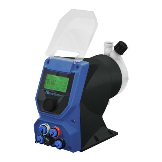
Page 7: Description
1. DESCRIPTION NextStep is a mechanically actuated, stepper motor driven diaphragm dosing pump with multiple 1.1 NEXSTEP Series control functions. The microprocessor controlled stepper motor ensures a homogeneous dosing process. The position and the speed of the diaphragm is controlled by the microprocessor electronics during the entire discharge/suction cycle. -
Page 8: Working Modes
Pump can work in different ways: 1.2 Working modes MODE WORKING MODES Pump doses at a constant rate set in “LPH” (liters per hour) or GPH CONSTANT (gallons per hour), during setup session. OZ PER PULSE The pump doses the quantity of product set for each impulse received. Dosing rate is determined by pulses from a water meter based on a PPM setpoint and chemical product concentration (%). -
Page 9: Features
1.4 Specs 1.5 Features ELECTRICAL 100-240 Vac - 50/60 Hz / 9-36VDC* Power supply *see pump’s label Power consumption 30 W Dry contact relay Alarm output MATERIALS Diaphragm PTFE NOVABLEND PC/ABS T110 FR Case PVDF Pump head (available) MECHANICAL Spring return mechanism Bleed valve valve Manual Double ball check valve... -
Page 10: Unpacking
Unpacking 1.7 List of ✓ : standard materials ✗: option available PVDF PPV0 PMMA GLASS PTFE FKM B EPDM ✓ ✗ ✗ PUMP HEAD ✓ DIAPHRAGM ✓ ✗ ✗ ✗ BALLS ✗ ✓ SUCTION HOSE ✓ ✗ DELIVERY HOSE ✗ ✓... -
Page 11: Product Description
2. PUMP’S DESCRIPTION 2.1 Control elements Control elements DESCRIPTION Multicolor backlight display to indicate pump status: GREEN: pump running WHITE: stand-by YELLOW: warning condition RED: alarm condition Multifunction rotary encoder CONNECTORS: RS485 ALARM INPUT LEVEL Main cable for power supply... -
Page 12: Pump Head
2.1 Pump head Control elements DESCRIPTION discharge connection venting knob (not in Stainless Steel pump head) venting connection (not in Stainless Steel pump head) suction connection... -
Page 13: Dimensions
2.3 Dimensions Fig. 2. Pump dimension - pump head mod. L DI MENSIONS NEXTSTEP NS1, NS2, NS4 8. 4 in 211. 7 5 mm 8.84 in /224. 5 0 mm 4. 5 2 in 1114. 7 5 mm 9.31 in 1236.40 mm 963 in/244 60 mm 2 36 in 160. - Page 14 Fig. 3. Pump dimension - pump head mod. N 2.4 Dimensions DIMENSIONS NEXTSTEP NS3, NS5 thru NS9 9 7 in 232 95 mm 9 45 tn /240 15 mm 4.52 in/ 114.75 mm 10.13 in 1257.35 mm 1047 in/265.85 mm 2.33 in /60.00 mm 9.17 in 3.94 tn...
-
Page 15: Installation
3. INSTALLATION 3.1 How to 5 steps to install and start-up the pump: install metering Choose a Pump location pump Make system connections (hoses, level probe, injection valve) Make electrical Wiring connections Prime the Pump the pump Programming and start The operator must be aware of safety precautions to prevent improper product performance serious injuries, including death, damage to the equipment and/or property damage. -
Page 16: Installation Drawings
Fig. 4. Installation drawing 3.6 Installation drawing... -
Page 17: Piping Connections
4. PIPING CONNECTIONS 4.1 Foot filter / The level probe is assembled with a foot valve and strainer to filter sediments. Level probe Install the foot valve so that it hangs near the bottom of the tank in a vertical position. -
Page 18: Suction Hose Connection
4.2 Suction hose connection Suction piping should be as short as possible and installed in vertical position to avoid air bubbles. Hand-tighten the nuts firmly. Do not use wrenches or any other tool. Fig. 6. Suction hose assembling Pipe holder Holding ring Threading nut Suction hose... -
Page 19: Injection Valve
Injection valve must be installed on plant. 4.4 Injection Injection valve will open at pressure greater than 4 psi. valve 4.5 Venting hose Insert one side of venting hose into discharge connector as shown in fig 8. Insert other side of venting hose into the solution tank. During the priming procedure chemical will flow into tank. -
Page 20: Electrical Wirings
5. ELECTRICAL WIRINGS 5.1 Preliminary THE ELECTRICAL WIRING SHOULD BE CARRIED OUT BY AUTHORIZED AND checks QUALIFIED PERSONNEL ONLY IN ACCORDANCE WITH LOCAL REGULATIONS. FAILURE TO DO SO MANY RESULT IN SERIOUS INJURIES, INCLUDING DEATH, DAMAGE TO THE EQUIPMENT AND/OR PROPERTY DAMAGE Before to proceed, verify the following steps: Verify the data on rating plate. -
Page 21: Connections
6. CONNECTIONS Description Cable Color Assignments 1 Green - RS485 + RS485 RS485 White MODBUS Brown 5 poles Blue connector Yellow version M12x1 Description Cable Color Assignments + RS485 1 Yellow RS485 or - RS485 2 Green MODBUS (option) 3 Blue mA Output 1 Yellow mA Output (option) -
Page 22: Start Up
7. START UP 7.1 Start up All operations previously described must be carried out before starting the pump. Pump location Piping connection Connections (power supply, stand-by/input, level, alarm output) Set up The pump could take up few seconds before start. It takes time for the motor to ramp up to full speed. -
Page 23: Priming
8. PRIMING Pump should be interlocked with a no-flow protected device to automatically shut- 8.1 Precautions off the pumps when there is no flow Take measures necessary shall be taken to prevent cross contamination of chemicals! Chemical feeding must be stopped during backwash cycles and periods of no flow as these conditions may introduce the potential for chemical overdosing. -
Page 24: Set Up
9. SET UP 9.1 Basic operations Main adjustment on encoder Choose a menu Rotate encoder on the menu items. Enter into the menu Press encoder on the menu item, the display will show the options available. Confirm a selection, save Press encoder on icon and go back to main... -
Page 25: Menu Overview
9.3 Menu overview HOME WORKING CONSTANT MODE MODE 16.0 SPEED � 0% ► 100% SLOW MODE 11,,. PRIMING STATISTICS SETTINGS INFO * From the menu Settings>More>View the display can be changed between "%" as the main unit and "g/h" or "l/h" as the main unit and "%" or "%" only. PRIMING .::a f PRIMING... - Page 26 STATISTICS STATISTICS > TOTAL > PARTIAL TOTAL STATISTICS > TOTAL > PARTIAL 10 gal DOSED: COUNTER: 0 DOSED: total quantity dosed (max 999.999.999 L). COUNTER: water meter counter. To reset all counters, see LOAD DEFAULT menu: SETTINGS / MORE / LOAD DEFAULT. >...
- Page 27 SETTINGS Setting session have an automatic timeout after 60 seconds, then go back to HOME screen. SETTINGS SELECTION MENU > WORKING MODE > MORE SETTINGS MENU Use this menu to set working mode and to define all settings.
- Page 28 WORKING MODE WORKING MODE MORE > CONSTANT > OZ PER PULSE > PPM > PERCENTAGE > MLQ > BATCH WORKING MODE > VOLT > MA > PULSE > PAUSE-WORK > WEEKLY PROGRAMMING Note: only the PERCENTAGE – PPM – CC-PULSE - MLQ - modes affect pulse sender water meter stats.
- Page 29 WHEN MODE PARAMETERS TO SET* NOTE Use this mode to dose a The pump doses at a GAL/h: GALLONS / HOUR. TURN THE constant rate constant flow rate KNOB TO THE REQUIRED GALLONS corresponding to a specific chemical up to the number of motor rotations.
- Page 30 Use this mode to dose HIGH:20.0mA Up to 21.965 GPH In mA mode, the pump chemical at a rate that LOW: 0.0 mA Up to 83.146 LPH doses proportionally is linearly scaled to between the low and high the current range mA values.
- Page 31 MORE WORKING MODE MORE > PUMP CAPACITY > TEST > LEVEL ALARM > STAND-BY > EXTERNAL INPUT > WATER METER MORE > TIMEOUT > OVERFLOW > UNIT OF MEASURE > DATA AND TIME POWER ON DELAY > MORE MORE > PASSWORD LANGUAGE >...
- Page 32 PARAMETERS TO SET NOTE FLOW 99 L/h, 26.15 gph •This setting is for setting the pumps Maximum PUMP Capacity. This setting SHOULD NOT be used to CC/MIN: 1650.00 CAPACITY change the current flow rate of the pump. SLOW MODE: 100% •Maximum flow rates will be adjusted automatically based on the slow mode setting.
-
Page 33: Pump Capacity Setting
•Date and Time Format can be changed as well as DATA & Format: dd/mm/yy 24 Format: mm/dd/yy 12 the actual time and date. CLOCK Date: Saturday 26/12/15 Date: Saturday 12/26/15 •Changing Data & Clock, partial statistics will be reset. time: 04:01:19 time: 04:01:19 am This setting allows the user to set the amount 00 to 10 min... - Page 34 INFO > INFO ALARMS > > RELEASE > mA OUT > RESERVE > INSTANT WM FLOW RATE Icon on main menu indicates one or more alarms active or stand-by. Tab. 1. Alarms management ALARM PROBLEM HOW MANAGE LEVEL No product Refill the tank Requested capacity by water Check settings...
-
Page 35: Electrical Wiring
10. ELECTRICAL WIRING The electrical wirings should be carried out by AUTHORIZED AND QUALIFIED 10.1 Preliminary checks PERSONNEL only in accordance with local regulations. Before to proceed, verify the following steps: Verify the data on nameplate. Make sure that the electrical data on the nameplate corresponds to the electrical supply. Verify the grounded power outlet. -
Page 36: Maintenance
11. MAINTENANCE 11.1 Check the equipment at least once a month to confirm that the requirements of Maintenance potable drinking water treatment and the maintenance requirements as declared schedule by the manufacturer are met. OPERATOR PROTECTION Use safety equipment according to local regulations. Use this safety equipment within the work area during installation, service and when handling chemicals: •... -
Page 37: Shutdown Procedure
If the pump performance does not satisfy your process requirements, and the process requirements have not changed, then perform these steps: 1. Disassemble the pump. 2. Inspect it. 3. Replace worn parts. This procedure SHOULD BE CARRIED OUT BY AUTHORIZED AND QUALIFIED 11.3 Shutdown procedure PERSONNEL... -
Page 38: Troubleshooting
12. TROUBLESHOOTING Tab. 6. Guide to troubleshooting. PROBLEM CAUSE REMEDY Suction valve leaking or blocked Clean or replace suction valve Suction pipe leaking or blocked Replace suction pipe Air bubbles into pump head or into suction Prime the pump as described in “Priming” Dosing pump not delivering pipe or output too low... -
Page 39: Flow Curves
13. FLOW CURVES Flow rate indicated is for H O at 20°C at the rated pressure. Dosing accuracy ± 1% at rated pressure. - Page 40 13. FLOW CURVES...
- Page 41 13. FLOW CURVES...
- Page 42 During the Warranty Period, in the event of a defect covered by the terms of this Warranty, Pulsafeeder, Inc. will, in its sole discre8on either: (i) repair the NextStep or any defec8ve part using either new or refurbished parts that meet the func8onal specifica8ons for the original NextStep,...
- Page 43 Product is delivered to you, whichever is longer. Any replaced parts (if the Product is repaired), or the original Product (if a replacement or refund is provided), will not be returned to you and will become the property of Pulsafeeder, Inc. LIMITATION OF LIABILITY LIMITATION OF LIABILITY The product should only be used for the purposes and in the manner specified in the manual.
- Page 44 8.2 Returns Contact our Customer Service Department by mail, phone or email: Pulsafeeder, Inc. at 27101 Airport Rd., Punta Gorda, FL, USA (941)575-3800 ppgpulsaspo.cs@idexcorp.com We will issue a Return Authoriza8on (RA) number for all returns. The following informa8on will be required: 1.
- Page 48 Disposal of end-of-life equipment by users This symbol warns you not to dispose of the produci with normai waste R espect human health and the environment b y giving the discarded equipment to a designated collection center lor the recycling of electronic and electrical equipment For more information visi! the online site.
Need help?
Do you have a question about the NextStep NS1 and is the answer not in the manual?
Questions and answers