Table of Contents
Advertisement
Quick Links
Electronic Metering Pumps
Class I, Div. 1 Groups C & D
Class I, Zone 1, Group IIB T5
Installation
Operation
Maintenance
Instruction
Tested and Certified by WQA
against NSF/ANSI/CAN 61
READ ALL WARNINGS
CAREFULLY
BEFORE
INSTALLING
1
PVDF and Degassing Head Pumps
See
www.wqa.org
for certification
parameters
L9408930-000 REV. D
Advertisement
Table of Contents

Related Manuals for Pulsafeeder Pulsatron X Series


Summary of Contents for Pulsafeeder Pulsatron X Series
- Page 1 Electronic Metering Pumps Class I, Div. 1 Groups C & D Class I, Zone 1, Group IIB T5 Installation Operation Maintenance Instruction Tested and Certified by WQA against NSF/ANSI/CAN 61 READ ALL WARNINGS CAREFULLY BEFORE INSTALLING PVDF and Degassing Head Pumps www.wqa.org for certification parameters...
-
Page 2: Table Of Contents
Table of Contents Product SAFETY ..............................4 DEFINTIONS .............................. 4 EXPLOSIVE ATMOSPHERE SAFETY ...................... 5 GENERAL SAFETY ........................... 5 INSTALLATION/OPERATION Safety ......................6 FIRE SAFETY ............................8 LIABILITY EXCLUSION ..........................8 SUITABILITY TO SITE OF INSTALLATION ....................9 NAMEPLATE AND MARKING ......................... 11 TRANSPORT AND STORAGE ........................ - Page 3 OPERATION BY EXTERNAL INPUT SIGNAL ..................23 6.10 STOP FUNCTION (ALL MODELS) ......................23 6.11 EXTERNAL PACING FUNCTION (PUMP MODEL STRING XP _ _ E)..........23 6.12 4-20mA DC INPUT FUNCTION (PUMP MODEL STRING XP _ _ M) ............. 24 MAINTENANCE ..............................
-
Page 4: Product Safety
PRODUCT SAFETY When using chemical feed pumps, you should always follow all safety precautions to reduce risk of explosion, fire, electric shock, and personal injury. Failure to follow these instructions could result in death or severe injury. Lorsque vous utilisez des pompes d'alimentation en produits chimiques, vous devez toujours suivre toutes les précautions de sécurité... -
Page 5: Explosive Atmosphere Safety
1.2 EXPLOSIVE ATMOSPHERE SAFETY RISK OF ELECTRICAL SHOCK EXPLOSION HAZARD -- REVIEW THIS ENTIRE MANUAL THOROUGHLY BEFORE PROCEEDING. DO NOT PERFORM INSTALLATION, OR MAINTENANCE OF ANY KIND ON THIS PRODUCT WHILE CIRCUIT IS LIVE AND THE AREA IS KNOWN TO BE HAZARDOUS. OPENING THE ENCLOSURE IS NOT REQUIRED. -
Page 6: Installation/Operation Safety
AVERTISSEMENT : Risque de choc électrique! L'installation électrique doit être conforme à tous les codes électriques locaux, régionaux et nationaux pertinents. Un électricien qualifié doit effectuer l'installation/la maintenance. Avant d'installer ou de réparer cet appareil, toute l'alimentation doit être coupée de la source. Assurez-vous que la tension de la pompe doseuse de produits chimiques correspond à... - Page 7 When starting a newly installed or restarting a maintained pump, use caution and protective measures to guard against hazards associated with the possibility of leaks (e.g., spraying of pumped chemical under pressure, leakage of fluid, etc.). When possible, apply pressure slowly and discontinue operation immediately if leakage is observed.
-
Page 8: Fire Safety
Product, or any irregularities or anomalies in its operation or function, you should stop using the Product immediately and contact Pulsafeeder or an authorized servicer. You should not attempt to repair the Product yourself or otherwise disassemble, modify, or tamper with it. -
Page 9: Suitability To Site Of Installation
In no event will Pulsafeeder, Inc. be liable for any loss, damage, or injury to the Product or to any person or property caused by: 1. Improper installation, operation, or maintenance of the Product by non-professional or inadequately trained operators. - Page 10 UNIQUEMENT UN CHIFFON HUMIDE POUR RÉDUIRE L'ACCUMULATION D'ÉLECTRICITÉ STATIQUE PENDANT LE NETTOYAGE. When so marked, the following standards apply to this product: Rating * Marking Standard Intermittent/Abnormal Hazard Class I, Div. 1, Group C, D T5 Explosion Proof UL 1203 Class I, Zone 1, Group IIB T5 Propane/Ethylene T5 = 100C...
-
Page 11: Nameplate And Marking
1.8 NAMEPLATE AND MARKING The PULSATRON X bears a standard rating nameplate on which it is possible to read, apart from functional data, all data required for universal identification. Pumps carrying the WQA certified to NSF/ANSI 61 & 372 marks are so certified when they include the De-gassing or PVDF pump head. -
Page 12: Storage Instructions
STORAGE INSTRUCTIONS 2.1 SHORT TERM (0 - 12 MONTHS) The PULSATRON X should be stored in a temperature and humidity-controlled environment. It is preferable to keep the temperature constant in the range of 32° to 104° Fahrenheit (0° to 40° Celsius). The relative humidity should be 0 to 90% non-condensing. -
Page 13: Materials Of Construction
The pump stroke rate is controlled by the circuit and is changed by turning the rate knob. mechanical stroke length is controlled by the stroke length knob. Adjusting these controls allows the output of the pump to be varied. 4.2 MATERIALS OF CONSTRUCTION The wetted materials (those parts that contact the solution being pumped) available for construction are FPP (glass filled polypropylene), PVC, CSPE, Viton, PTFE or FTF, 316 Stainless Steel, PVDF, Ceramic and Alloy C. -
Page 14: Pump Mounting
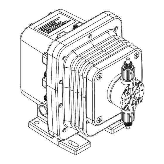
5.2 PUMP MOUNTING Typical pump mounting arrangements are shown below. Important: Injection point must be higher than the top of the solution supply tank to prohibit gravity feeding unless suitable backpressure is always present at the injection point. Installation of an anti-siphon valve will prohibit gravity feeding. For Wall or Shelf mounting, connect the suction tubing/pipe to suction valve of chemical pump. -
Page 15: Piping
5.4 PIPING Supplied Tubing is NOT static dissipative and may not meet location requirements. Consult site Hazardous Location Expert for suitability for use. La tuyauterie fournie n'est PAS antistatique et peut ne pas répondre aux exigences d'emplacement. Consultez le spécialiste des emplacements dangereux du site pour déterminer la compatibilité. -
Page 16: Integrity Of The Enclosure
CONDUIT QUI A UNE COTE POUR EMPLACEMENT DANGEREUX ÉQUIVALENTE OU SUPÉRIEURE. If questions arise about the conduit or cable glands during installation or servicing, contact Pulsafeeder field service or applications engineering for assistance. WHEN USED IN HAZARDOUS ENVIRONMENTS, ALL CONDUIT ENCLOSURE... -
Page 17: Codes And Regulations
WIRE SHOULD BE ROUTED IN A MANNER THAT MAINTAINS SEPARATION BETWEEN LINE AND EXTRA-LOW VOLTAGE (E.G., 4-20mA/PACE) CONDUCTORS. APPLICABLE NATIONAL AND LOCAL ELECTRICAL CODES TAKE PRECEDENCE OVER RECOMMENTATIONS BELOW. LES CODES ÉLECTRIQUES NATIONAUX ET LOCAUX APPLICABLES ONT PRIORITÉ SUR LES RECOMMANDATIONS CI-DESSOUS. -
Page 18: Signal Input Wiring
5.6.3 SIGNAL INPUT WIRING The Signal Input connections are made to flying leads to the left of the control panel. The leads are labeled as follows: XP**E XP**M Signal Input includes standard External Stop and optional External Pace (XP**E) or External 4-20mA analog signal (XP**M) to control the stroking rate of the pump. -
Page 19: Grounding
5.6.4 GROUNDING APPLICABLE NATIONAL AND LOCAL ELECTRICAL CODES TAKE PRECEDENCE OVER RECOMMENDATIONS LES CODES ÉLECTRIQUES NATIONAUX ET LOCAUX APPLICABLES ONT PRIORITÉ SUR LES RECOMMANDATIONS. The primary incoming power electrical ground should be attached to the GREEN ground lead as defined in section Power Wiring. -
Page 20: Operation And Startup
OPERATION AND STARTUP 6.1 PUMP CONTROL PANEL The pump control panel includes 3 basic controls – Operating Mode, Stroke Rate Setting and Stroke Length Setting. 6.2 OPERATING MODE The operating mode is set by a 3-position switch in the lower left corner of the control Panel. -
Page 21: Pre-Startup Checklist
6.5 PRE-STARTUP CHECKLIST Before powering the pump for the first time: Put on PPE in accordance with chemical in use Safety Data Sheet. Check Lockout/Tagout State. Confirm incoming power matches Pump Nameplate. Confirm power and signal connections are complete. ... -
Page 22: Capacity Control
Moisten the discharge valve area (ball check and valve seats) with a few drops of chemical being fed to the metering pump. g. Replace the discharge fitting. h. Clean any spilled chemical from the Pump Head, Valves, Piping and Pump Housing. Open the suction and discharge isolation valves. -
Page 23: Operation By External Input Signal
Selected Model = XPK4 Set Stroke Length = 100% Maximum Flow* = 31 gallons per day (GPD at Rated Pressure) Desired Flow = 15 GPD Set Stroke Rate = 15/31 = 0.48 = 48% * Check these values by measurement - Output capacity is higher when feeding against less than rated pressure. -
Page 24: 4-20Ma Dc Input Function (Pump Model String Xp
The input signal must be in the form of closure of a mechanical relay, mechanical switching device (e.g., float switch), or of a solid- state switching device. Voltage signals are prohibited. switching resistance of either mechanical or solid-state devices must be 100 ohms or below when ON and 1 megohm or above when OFF. -
Page 25: Operating Precautions
TECHNICIANS, TAKING INTO ACCOUNT THE SERVICE AND THE ACTUAL ENVIRONMENTAL CONDITIONS IN WHICH IT OPERATES. TOUS LES TRAVAUX DE MAINTENANCE DOIVENT ÊTRE EFFECTUÉS UNIQUEMENT LORSQUE LE PRODUIT ET L'ÉQUIPEMENT CONNECTÉ SONT ARRÊTÉS ET DÉBRANCHÉS DE L'ALIMENTATION SECTEUR (Y COMPRIS LES CIRCUITS AUXILIAIRES). LE MAINTIEN DES CARACTÉRISTIQUES ORIGINALES DANS LE TEMPS DOIT ÊTRE ASSURÉ... -
Page 26: Disassembly / Re-Assembly
For optimum performance, cartridge valves should be changed every 6-12 months. Depending on the application, more frequent changes may be required. Actual operating experience is the best guide in this situation. Repeated short-term deterioration of valve seats and balls usually indicates a need to review the suitability of wetted materials selected for the application. -
Page 27: Valve Replacement
Adjust stroke length only when pump is running! Adjust stroke length back to 100% for easier priming and place pump back into service. 8.3 VALVE REPLACEMENT Flush pump to clean any chemical from pump head. Disconnect power from the pump, release system pressure, and disconnect tubing or piping. Unscrew valve cartridges and discard. - Page 28 4. Carefully tip Power Module End (Black) towards Pump Head exposing fuse. 5. Locate fuse in protective loom: 6. Cut cable ties to expose fuse assembly. Replace with 2A 240VAC Sealed Slo-Blow Fuse (Pulsafeeder PN: L9707300-000 [Little Fuse PN: 0225002.HXP]). 7. Replace covering and retaining Cable ties. Cover Re-installation 1.
-
Page 29: Troubleshooting
TROUBLESHOOTING Issue Probable Cause Remedy 1. Leak in suction side of 1. Examine suction tubing. If worn at the end, cut pump approximately one inch (2.5cm) off and reconnect 2. Clean valve seats if dirty or replace with alternate 2. Valve seats not sealing material if deterioration is noted 3. - Page 30 Issue Probable Cause Remedy 1. Worn tube ends 1. Cut off end of tubing approximately one inch Leakage at (2.5cm) and reconnect Tubing Connections 2. Chemical attack 2. Consult your seller for alternate material 1. Loose fittings 1. Tighten hand tight. Replace gasket if hand tightening does not stop leakage Leakage at...
-
Page 31: Policies And Procedures
During the Warranty Period, in the event of a defect covered by the terms of this Warr anty, Pulsafeeder, Inc. will, in its sole discretion either: (i) repair the PulsatronX or any defective part using either new or refurbished parts that... -
Page 32: Returns
TO THE MAXIMUM EXTENT PERMITTED BY LAW, PULSAFEEDER, INC. SHALL HAVE NO LIABILITY WHATSOEVER FOR ANY INDIRECT, INCIDENTAL, CONSEQUENTIAL, PUNITIVE OR SPECIAL DAMAGES, INCLUDING BUT NOT LIMITED TO LOST PROFITS OR COMMERCIAL LOSS, LOSS OF GOODWILL OR BUSINESS INTERRUPTION, WHETHER RESULTING FROM BREACH OF WARRANTY, TORT, CONTRACT OR ANY OTHER LEGAL OR EQUITABLE THEORY, AND THE ENTIRE LIABILITY OF PULSIFEEDER, INC. - Page 33 Pulsafeeder, Inc. 27101 Airport Rd. Punta Gorda, FL 33982 USA (941) 575-3800 www.pulsa.com L9408930-000 REV-D...
Need help?
Do you have a question about the Pulsatron X Series and is the answer not in the manual?
Questions and answers