
Related Manuals for Pulsafeeder PulsaPro PP7440


Summary of Contents for Pulsafeeder PulsaPro PP7440
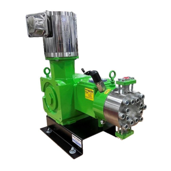
- Page 1 PulsaPro ® HYDRAULIC DIAPHRAGM METERING PUMPS PP7440 Installation, Operation & Maintenance Manual Bulletin: IOM-PRO-003 Rev A...
-
Page 2: Pulsafeeder Factory Service Policy
Parts purchased to correct a warranty issue may be credited after an examination of original parts by Pulsafeeder. Warranty parts returned as defective, which test good, will be sent back freight collect. No credit will be issued on any replacement electronic parts. If the product requires returning to the factory for inspection and/or repair, a Return Authorization Number (RMA) issued by Pulsafeeder is mandatory. -
Page 3: Table Of Contents
Contents Table Pulsafeeder Factory Service Policy……………………………………...……...…… Trademarks………………………………………………………………..…...……. Safety Considerations…………………………………………………………..…… 1. Introduction………………………………………………………………………. 1.1 Receiving Inspection………………………………………………………………. 1.2 General Information………………………………………………………………… 1.3 Personnel Responsible for Pump Operation…………………………………. 1.4 Testing………………………………………………………………………………. 1.5 Warranty……………………………………………………………………………. 1.6 Requesting Spare Parts………………………………………………………… 1.7 Spare Parts…………………………………………………………………………. 1.8 Liability Exclusion…………………………………………………………………… 6 1.9 Restrictions Regarding this document…………………………………………. - Page 4 8.6 Check Valves……………………………………………………………………… 8.7 Hydraulic Performance Valve (HPV)………………………………………… 8.8 Hydraulic Bypass Valve (HBV)…………………………………………………. 8.9 Push to Purge (PTP)…………………………………………………………… 8.10 Piston Seals……………………………………………………………………… .32 8.11 Oil Seal……………………………………………………………………………. 34 8.12 Pump Motor Removal and Reinstallation……………………………………... 9. Troubleshooting………………………………………………………………. 10. Technical Service Support………………………………………………... 10.1 Authorized Service Centers……………………………………………………. 10.2 Local Sales Representatives…………………………………………………...
-
Page 5: Introduction
Pulsafeeder to obtain a copy. For drawings and bill of materials for your pump(s) please send an email to Prodocs@idexcorp.com. Using the nomenclature of the sectional drawing, make a list of the parts needed and send to your local Pulsafeeder sales representative, always specify the pump serial number. -
Page 6: Spare Parts
585-292-8000 1.7 Spare Parts Modifications are not allowed. Original Pulsafeeder spare parts and accessories are to be used to assure conformity with safety rules. Pulsafeeder declines any responsibility in case of use of non- original parts and which results in the warranty being voided. -
Page 7: Storage Instructions
See Appendix I for more information. After twelve months of storage, Pulsafeeder Warranty cannot cover such items which are subject to deterioration with age such as seals and gaskets. If the pump has been in storage longer than twelve (12) months, it is recommended that such items be inspected and replaced as necessary prior to startup. -
Page 8: Nameplate Identification
Figure 1 4.2 Nameplate Identification Each pump carries a nameplate for identification with the following information: Model Series Serial Number Rated Flow Rated Pressure KOPkit (recommended spare parts) Piston Diameter Gear Ratio Motor Frame Size, RPM Rating Figure 2 Page 8 of 48... -
Page 9: Flow Rate
4.3 Flow Rate PulsaPro has pulsating flow rates, generated by the alternating movement of the piston and the action of the check valves on the pump head which determine flow direction. Pump flow rate is adjustable and increases or decreases in direct proportion to the variation of the stroke adjustment. The theoretical flow rate –... - Page 10 Types of Diaphragms – PulsaPro 7440 offer the Flat Diaphragm and HYDRAtube. Additionally, you can utilize our Double Diaphragm (Flat) with PULSAlarm Leak detection. (Figure 4 showing the Flat diaphragm and HYDRAtube. Figure 4 Flat Diaphragm – is the standard design ensuring high performance metering in a leak-free operation.
- Page 11 Double Diaphragm (Flat) with PULSAlarm Leak Detection – offers a rugged sandwich style double diaphragm construction for increased protection against leaks. PULSAlarm provides a pressurized leak detection technology to monitor the diaphragm integrity and can signal an alarm or stop the pump at the first sign of diaphragm failure.
- Page 12 Hydraulic Bypass Valve (HBV) – this valve protects the pump from over-pressurization by relieving any excess pressure in the pump’s hydraulic system. The valve is preset based on customer’s specification, typically adjusted to 10% above the system pressure. The sight glass above the valve allows visual aid to observe the operation.
- Page 13 Automatic Stroke Adjustment If ordered with a controller you would have the XAE which is a microprocessor-based stroke length control device. The unit is physically attached and integrated into the pumps design. This controller allows for precise adjustment of output flow of a process media by means of stroke length position. For additional information on your XAE please download or review a copy of the IOM.
-
Page 14: Installation
Whenever pumps are multiplexed, the eccentric shafts are positioned to place a uniform load on the driver. Before full disassembly, always note the relative positions of the eccentric shafts to each other so they can reassemble in the same orientation. Installation 5.1 Location When selecting an installation site or designing a skid package, consideration should be given to access... -
Page 15: Suction Pressure Requirements
All piping systems should include: Shutoff valves and unions (or flanges) on suction and discharge piping. This permits check valve inspection without draining long runs of piping. Shutoff valves should be the same size as connecting pipe. Ball valves are preferred since they offer minimum flow restriction. -
Page 16: Discharge Pressure Requirements
5.4 Discharge Pressure Requirements PulsaPro Metering Pumps are designed for continuous service at the rated discharge pressure. If system suction pressure exceeds system discharge pressure, flow would be generated in addition to that caused by the pump, resulting in a reduction in accuracy and loss of control over the metering process. -
Page 17: Equipment Setup
Equipment Setup 6.1 Hydraulic Oil Fill The PulsaPro ships from the factory pre-filled with oil after testing is completed. When starting up you can verify the oil level from the provided sight glass on the gearbox as well as the Intermediate Head. -
Page 18: Drive Motor Wiring
6.3 Drive Motor Wiring Wire the PulsaPro drive motor according to the motor vendor’s nameplates and instructions, and according to any appropriate national and local electrical codes and regulations. 6.4 Motor Rotation Verification of the motor direction is necessary at startup. The motor direction must be counterclockwise as indicated on the gearbox by a directional arrow. -
Page 19: Priming The Pump Head
Before operation of any PulsaPro pump, carefully ensure that all suction valves are in the open position. Verify that all filters and strainers are clean and clear. Ensure that any other potential causes of restriction have been addressed. Unrestricted flow of liquid to the suction side of the pump is critical to proper operation. -
Page 20: Maintenance
To construct a calibration chart, measure the flow rate several times at three or more stroke settings (i.e., 25, 50, 75, and 100), plot these values on linear graph paper, and draw a best fit line through the points. For stable conditions, this line should predict settings to attain required outputs. See figure 2 for example of a four-point test plotted onto a calibration chart. -
Page 21: Consulting With Technical Documentation
All operations must be performed by qualified personnel. Prior to work: The power line is disconnected, and no parts are energized Any risk of accidental restart has been excluded Handled fluid, present in the pump head and pipelines is not pressurized With the pump off, suction and discharge valves are closed Pump has been adequately cleaned, when operating in aggressive chemical environments THESE MAINTENANCE SUGGESTIONS ARE NOT INTENDED AS “DO IT YOURSELF”... - Page 22 Flat Diaphragm Replacement Procedure: Disconnect the power source to the drive motor. Relieve all pressure from the piping system. Take all precautions to prevent environmental and personnel exposure to hazardous materials. Close the inlet and outlet shutoff valves. Place a suitable container underneath the pump head to catch any liquid leakage. Disconnect piping to the reagent head and drain process liquid, following material safety precautions described.
- Page 23 FOR ELASTOMER HYDRATUBES FOLLOW STEPS 8 THROUGH 20. FOR PFA HYDRATUBES FOLLOW STEPS 21 THROUGH 35. 8. Pick up on the edge of the HYDRAtube flange and push that same edge down the throat of the HYDRAtube. The balance of the flange will fold and follow. 9.
-
Page 24: Priming
24. Pull the HYDRAtube out from the bottom by a combination of twisting and bending. Also remove any gaskets which were beneath the bottom tube adaptor. 25. Inspect the tube for any damage (i.e.; cuts, cracks, chemical attack). Replace if necessary. 26. - Page 25 8. Replace the PTP valve in the pump head, ensuring that the flat copper gasket and O-ring are properly in place. 9. Restore power to the pump. Increase the stroke slowly to 100% depressing and holding the PTP valve periodically. Oil should begin to flow out of the center diagnostic port. Continue to hold the valve down until the oil is clear of bubbles.
-
Page 26: Check Valves
suction stroke to an elliptical shape at full discharge stroke, but not closing off at the middle. The pump now has a correct intermediate prime and is ready for service. • Reinstall the suction and discharge valve assemblies. Double Diaphragm Flat Leak Detection Please refer to Appendix I for detailed information for priming of the Leak Detection Diaphragm. - Page 27 to disconnect a union or flange. Remove the suction check valve assembly (ball contained within guide and seat), holding it together as a unit. Loosen the tie bar bolts on the discharge valve and spring the piping slightly to drain any liquid. Remove the discharge valve assembly, holding it together as a unit as before.
-
Page 28: Hydraulic Performance Valve (Hpv)
8.7 Hydraulic Performance Valve (HPV) PulsaPro pumps utilize the high-performance valve which is integrated within the dish plate to preserve hydraulic balance. The valve is factory preset and requires no maintenance provided the hydraulic oil remains clean. When the valve is actuated, oil can flow into the hydraulic system until the piston reaches the end of the suction stroke. -
Page 29: Hydraulic Bypass Valve (Hbv)
8.8 Hydraulic Bypass Valve (HBV) All PulsaPro pumps incorporate a hydraulic bypass valve which is an adjustable spring-loaded valve ported into the hydraulic cavity of the pump head. The valve is designed to protect the pump against excessive hydraulic pressure and will not limit or regulate system pressure. The valve is factory adjusted for pressure as originally specified, or at 10% above the rated pressure. -
Page 30: Push To Purge (Ptp)
PTP Port Bypass Side Figure 38 8.9 Push to Purge (PTP) The PTP is a gravity operated ball check valve that automatically removes gases from the hydraulic system. On each discharge stroke of the pump, hydraulic pressure drives the ball off the lower seat, expelling any accumulation of gases at the top of the hydraulic system. -
Page 31: Piston Seals
Under normal operating conditions this ongoing process removes accumulation of gas long before they are visible or detrimental to pump operation. To accelerate hydraulic startup, pressing the spring-loaded button at the top of the valve holds the valve momentarily open so that large amounts of gas can be instantly purged. - Page 32 Removal and Replacement of Piston Seals (small piston sizes 7/8” and under) With any maintenance performed, follow safety procedures in place. Lockout/Tagout, relieve pressure, close valves, flush the reagent head, drain the hydraulic oil. Remove the reagent head from the pump head. Remove the four bolts that secure the pump head to the intermediate head.
-
Page 33: Oil Seal
8.11 Oil Seal The PulsaPro pumps utilize an oil seal on the worm shaft (input shaft) like the Pulsa product line. This seal is serviceable, but only necessary to replace if there is an oil leak. Replacing the Oil Seal Power has been disconnected from the source;... -
Page 34: Troubleshooting
Troubleshooting Chart ISSUE POSSIBLE CAUSES REMEDY Check voltages, frequency, wiring, and terminal Motor Speed too low connections. Check nameplates vs. specifications. Check Valves worn or dirty Clean of any debris, replace if damaged or worn Flow Rate Lower Hydraulic bypass valve operating Refer to Hydraulic Bypass Valve than Expected each stroke... -
Page 35: Technical Service Support
Solutions may include purchase of replacement parts or returning the unit to the factory for inspection and repair. All returns require a Return Authorization Number issued by Pulsafeeder through your local representative. Pulsafeeder cannot accept any pump, part, or piping accessory that has pumped strong odorants (such as mercaptan). -
Page 36: Pulsalarm Leak Detection System
APPENDIX I 11.1 PULSAlarm® Leak Detection System The PULSAlarm® leak detection system utilizes a two-layer PTFE diaphragm, coupled to a pressure switch. The system is initially primed by filling the void within the detection assembly and between the diaphragm layers with a barrier fluid. The setup process then bleeds excess fluid from between the diaphragm layers until they are in close contact. - Page 37 11.2.1 Reinstallation of Leak Detection Diaphragm 1. Ensure that the critical sealing areas of diaphragm assembly, reagent head, and pump head are clean and free from debris. 2. Place a dab of grease on the back of the rear diaphragm. Note the rear diaphragm has swirls on the face.
- Page 38 8. Place the diaphragm onto the reagent head; ensuring the capillary tubes are seated into the pre-drilled holes in the reagent head. 9. Place the leak detection spacer onto the diaphragm. Ensure that the capillary tubes are in the slots as shown. 10.
- Page 39 13. Once attached, remove the clips as shown 14. Install remaining head bolts. Torque the bolts per the recommended torque settings. Page 39 of 48...
-
Page 40: Priming Of Leak Detection Diaphragm
11.3 Priming of Leak Detection Diaphragm IF THE LEAK DETECTION SYSTEM IS OPENED TO THE ATMOSPHERE DURING MAINTENANCE OR INSPECTION, THE SYSTEM MUST BE RE-PRIMED PROPERLY TO AVOID DIAPHRAGM DAMAGE AND ENSURE PROPER LEAK DETECTION OPERATION AND SYSTEM PERFORMANCE. THE STANDARD FACTORY INTERMEDIATE FLUID IS A SILICON OIL. IF ANY OTHER CUSTOMER SPECIFIED MEDIA IS USED, IT MUST BE COMPATIBLE WITH THE MATERIALS OF CONSTRUCTION. -
Page 41: Appendix
APPENDIX II 12.1 Piping Calculations All reciprocating metering pumps require a net positive suction head (NPIP R ). Refer to Table 1 for the (NPIP R ) required for PULSAPRO pump models. The NPIP R is defined as the pressure required above the absolute vapor pressure of the process fluid at the pumping temperature. -
Page 42: System Back Pressure
12.2 System Back Pressure The system back pressure must exceed the suction pressure by at least five (5) psi (0.35bar) to prevent flow through, however it must not exceed the rated discharge pressure of the pump. Flow through can be defined as the process liquid flowing from a higher pressure to a lower pressure, which attributes to pump failure and undesired flow at pump shutdown. -
Page 43: Nomenclature
12.3 Nomenclature Table 3A – Definitions of abbreviations used in NPIP Equations NPIP R Net positive inlet pressure required, [psi, bar] NPIP A Net positive inlet pressure available, [psi, bar] Pressure at the surface of the liquid being pumped (atmospheric or supply tank blanket pressure) [psi(a), bar(a)] Head pressure above (+) or below (-) the pump centerline, [psi, bar,] (convert from ft or m) -
Page 44: Appendix
APPENDIX III 13.1 Oil Specification PULSALube Ultra 8GS Synthetic Gear Oil PULSAlube Premium 7H Hydraulic Oil Please visit our website at www.pulsafeeder.com to view and download any Safety Data Sheet (SDS) under the Resources tab. Page 44 of 48... -
Page 45: Bolt Torque Recommendations
The torque valve is based on the reagent head part number which is stamped or cast on the part itself. If assistance is needed in identifying your specific torque value for your pump please contact the local representative or the Pulsafeeder Service Group at 585-292-8000 or via email at ProService@idexcorp.com... -
Page 46: Pulsatrol Pulsation Dampener
APPENDIX V – Accessories 15.1 PULSAtrol Pulsation Dampener The PULSAtrol is a pneumatically charged diaphragm-type chamber that intermittently stores energy. Used on the inlet, it will improve NPIP A (Net Positive Inlet Pressure available) characteristics of the suction piping system. On the discharge line it will reduce peak pressures and pulsating flow variations. -
Page 47: Back Pressure Valve
15.2 Back Pressure Valve The Pulsafeeder diaphragm backpressure valve creates constant backpressure. A PTFE diaphragm, offering maximum chemical protection and service life, seals the spring and bonnet from process fluid. This diaphragm seals directly on a replaceable seat. Be sure to install with fluid flow in direction of arrow on valve body. - Page 48 Pulsafeeder, Inc. 2883 Brighton Henrietta Town Line Road Rochester NY 14623 +1 (585) 292-8000 www.pulsafeeder.com Page 48 of 48...
Need help?
Do you have a question about the PulsaPro PP7440 and is the answer not in the manual?
Questions and answers