
Related Manuals for Pulsafeeder PULSAR 25HJ


Summary of Contents for Pulsafeeder PULSAR 25HJ
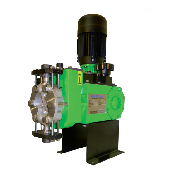
- Page 1 Installation, Operation & Maintenance Manual Bulletin: IOM-PSR-1500-Rev.G ® PULSAR HYDRAULIC DIAPHRAGM METERING PUMPS...
- Page 2 All returns require a Return Authorization number to be issued by Pulsafeeder. Parts purchased to correct a warranty issue may be credited after an examination of original parts by Pulsafeeder.
- Page 3 • General review update • Remove Vacuum Leak Detection Additional information regarding your pump can be found by going to our Pulsafeeder website WWW.Pulsa.com If you need further assistance, you can contact our service department by calling 585-292-8000, or by emailing us at...
-
Page 4: Table Of Contents
Table of Contents 1. INTRODUCTION ..........................1 GENERAL DESCRIPTION ....................... 1 2. PRINCIPLES OF OPERATION......................1 OVERALL OPERATION ......................1 COMPONENT LOCATION AND OPERATION ............... 2 2.2.1 Reagent Head Assembly ....................2 PULSAlarm LEAK DETECTION ..................... 3 2.2.2 Pump Head/Piston assembly ..................3 2.2.3 Control Assembly ...................... - Page 5 PULSAlube # 8G ..........................42 14. APPENDIX IV ............................. 43 BOLT TORQUE RECOMMENDATIONS ....................43 15. APPENDIX V ............................44 PULSAFEEDER ACCESSORIES ......................44 PULSATROL INSTALLATION, OPERATION, & REMOVAL INSTRUCTIONS ......... 44 INSTALLATION ..........................44 PULSATROL REMOVAL ......................... 45 BACK PRESSURE VALVE ........................46...
-
Page 6: Introduction
1. INTRODUCTION GENERAL DESCRIPTION PULSAR metering pumps are positive displacement reciprocating pumps. They combine the high efficiency of the plunger pump with diaphragm sealing to prevent product leakage. Each pump consists of a power end and a process end separated by a hydraulically operated diaphragm. -
Page 7: Component Location And Operation
COMPONENT LOCATION AND OPERATION Figure 2 2.2.1 Reagent Head Assembly The typical reagent head assembly consists of reagent head, diaphragm, and suction and discharge check valves. This assembly is the only part of the pump to contact the process liquid; consequently, maintenance is critical to pump performance. -
Page 8: Pulsalarm Leak Detection
PULSAlarm LEAK DETECTION The PULSAlarm Pressure leak detection reagent head assembly consists of a leak detection reagent head, leak detection diaphragm, suction and discharge check valves, and optional pressure switch and gauge. If your pump is equipped with this option, refer to Appendix I on page 33 for further information. -
Page 9: Control Assembly
20-24 In-lbs. (225 – 270 N-cm). PULSAR pumps may also be equipped with the Pulsafeeder DLC or DLCM electronic stroke length controllers. These allow for local and/or remote automatic control over stroke length (DLC) or stroke length and motor speed (DLCM). - Page 10 2.2.5 Gear Ratio Assembly Figure 6 PULSAR pumps are driven by a standard C-face electric motor mounted on the motor adaptor input flange. The motor drives a set of worm gears which convert rotational speed into torque. They in turn power the eccentric shaft assembly that converts rotary motion to reciprocating motion.
-
Page 11: Equipment Inspection
PULSAlarm pressure leak detection system, See Appendix I on page 33 for more information. After twelve months of storage, Pulsafeeder’s warranty cannot cover such items which are subject to deterioration with age such as seals and gaskets. If the pump has been in storage longer than 12 months, it is recommended that such items be inspected and replaced as necessary prior to startup. -
Page 12: Installation
4. INSTALLATION LOCATION When selecting an installation site or designing a skid package, consideration should be given to access for routine maintenance. PULSAR pumps are designed to operate indoors and outdoors, but it is desirable to provide a hood or covering for outdoor service. External heating may be required if ambient temperatures below -18... -
Page 13: Suction Pressure Requirements
1. Shutoff valves and unions (or flanges) on suction and discharge piping. This permits check valve inspection without draining long runs of piping. Shutoff valves should be of the same size as connecting pipe. Ball valves are preferred since they offer minimum flow restriction. 2. -
Page 14: Discharge Pressure Requirements
Suction restrictions can place stress on the diaphragm that may result in premature failure. Refer to Appendix II for procedures for the calculation of suction pressure. DISCHARGE PRESSURE REQUIREMENTS All PULSAR Metering Pumps are designed for continuous service at the rated discharge pressure. -
Page 15: Equipment Setup
Please note that the eccentric box section of the pump is not completely full when the proper amount of oil is used, this is normal. Starting in production year 2007, Pulsafeeder will distribute PULSAlube 7H in 1-liter containers to facilitate proper oil fill. -
Page 16: Hydraulic Oil Fill
of the required level. Replace both pipe plugs after filling. Do not add oil through the port on the side of the motor adapter, as this port is for motor drive coupling access only. 5.1.3 Hydraulic Oil Fill Remove the diagnostic window to gain access to the reservoir and add PULSAlube 7H hydraulic oil until the oil level is between the max and min as indicated on the label on the side of the eccentric box. -
Page 17: Pulsalarm Leak Detection
PULSAlarm LEAK DETECTION Refer to Appendix I, page 33 for startup instructions specific to pumps equipped with the PULSAlarm diaphragm leak detection system DRIVE MOTOR INSTALLATION 5.2.1 Motor Rotation Motor can be operated in either direction, clockwise or counterclockwise. Verification of motor direction is not necessary at startup. -
Page 18: Electrical
Wire the PULSAR drive motor according to the motor vendor’s nameplates and instructions, and according to any appropriate national and local electrical codes and regulations. If the motor is to be utilized with a Pulsafeeder controller, such as the DLC, DLCM, or MPC, consult the appropriate Pulsafeeder IOM for further motor wiring instructions. -
Page 19: Suction System
Leak Detection Diaphragm systems require special hydraulic priming considerations to protect the diaphragm from damage during initial pump startup. See Appendix I on page 33 for further information. Suction System Before operation of any PULSAR pump, carefully ensure that all suction valves are in the open position. -
Page 20: Calibration
Calibration Figure 13 All metering pumps must be calibrated in order to accurately specify stroke length settings for required flow rates. For pumps provided with DLC or DLCM electronic stoke length control, refer to separate instructions as noted on page 8. A typical calibration chart is shown in Figure 13. -
Page 21: Checking The Diagnostic Window
CHECKING THE DIAGNOSTIC WINDOW Bypass port (side) PTP port (center) BYPASS PORT PTP PORT Connected to The hydraulic bypass valve The PTP push-button valve on the side of the pump head on the top of the pump head Function Bypass protects the pump Allows any air trapped in the from excessive pressure and hydraulic system to escape... -
Page 22: Maintenance
7. MAINTENANCE EFORE PERFORMING ANY MAINTENANCE REQUIRING REAGENT HEAD OR VALVE WET END DISASSEMBLY BE SURE TO RELIEVE PRESSURE FROM THE PIPING SYSTEM AND WHERE HAZARDOUS PROCESS MATERIALS ARE INVOLVED RENDER THE PUMP SAFE TO PERSONNEL AND THE ENVIRONMENT BY CLEANING AND CHEMICALLY NEUTRALIZING AS APPROPRIATE EAR PROTECTIVE CLOTHING AND EQUIPMENT AS APPROPRIATE Accurate records from the early stages of pump operation will indicate the type and levels of required maintenance. -
Page 23: Hydraulic Oil Change
7.1.2 Hydraulic Oil Change: The recommended hydraulic oil change interval is 2 years for normal service and 1 year for severe service. Hydraulic Oil change procedure is as follows: 1. Disconnect the power source to the drive motor. 2. Relieve all pressure from the piping system. 3. -
Page 24: Standard Diaphragm Replacement
7.2.1 Standard Diaphragm Replacement Figure 14 PULSAR diaphragms do not have a specific cycle life; however, the accumulation of foreign material or the entrapment of sharp particles between the diaphragm and dish cavity can eventually cause failure. Failure can also occur as a result of hydraulic system malfunction or chemical attack. -
Page 25: Re-Priming The Pump Head
7.2.2 Re-Priming the Pump head Figure 15 Leak Detection diaphragm systems require special hydraulic priming considerations to protect the diaphragm from damage during initial pump startup. Refer to Appendix I, page 33 and review these procedures carefully before re-starting a PULSAR pump equipped with a leak detection system. -
Page 26: Check Valves
CHECK VALVES 7.3.1 General Description Most fluid metering problems are related to check valves. Problems usually stem from solids accumulation between valve and seat, corrosion of seating surfaces, erosion, or physical damage due to wear or the presence of foreign objects. -
Page 27: Hydraulic Performance Valve (Hpv)
HYDRAULIC PERFORMANCE VALVE (HPV) 7.4.1 General Description During normal pump operation hydraulic fluid is continually discharged through the automatic bleed valve and may also be lost past the piston seals. This causes the diaphragm to be drawn further back on each successive suction stroke until it actuates the HPV. Once the valve is actuated, oil is allowed to flow into the hydraulic system until the piston reaches the end of the suction stroke. -
Page 28: Hpv Removal And Replacement - A & B Pump Head Style
7.4.3 HPV Removal and Replacement - A & B Pump head Style Use the following procedure for a HPV Removal and Replacement (A & B Pump head Style) 1. Remove the reagent head and diaphragm and drain hydraulic oil from the eccentric box. 2. -
Page 29: Hpv Removal And Replacement - C & D Pump Head Style
12. Make certain that the diagnostics seal at the top of the eccentric box flange and the HPV feed port o-ring at the bottom of the flange are in place (refer to Figure 4). 13. Insert the pump head into the eccentric box using the locating pins as a guide. 14. -
Page 30: Hydraulic Bypass Valve (Hbv)
9. Make certain that the diagnostics seal at the top of the eccentric box flange and the HPV feed port o-ring at the bottom of the flange are in place (refer to Figure 4). 10. Insert the pump head onto the eccentric box using the locating pins as a guide. 11. -
Page 31: Ptp (Push To Purge / Automatic Bleed Valve)
system but no more than 10% over the pump’s rated pressure. After adjustment tighten the lock nut and reinstall the plastic cover. Periodic inspection of the valve seat is recommended. If it becomes worn or damaged leakage will occur regardless of how tightly the valve is adjusted. PTP (PUSH TO PURGE / AUTOMATIC BLEED VALVE) 7.6.1 General Description... -
Page 32: General Description
Figure 21 Figure 22 7.7.1 General Description The piston seals are of carbon graphite reinforced TFE U-cup construction with a stainless steel energizer spring. The seal is mounted two different ways: on the piston (for the larger piston sizes – Figure 22) or in the cylinder (for the smaller piston sizes – Figure 21). With oil changes at recommended intervals, piston seals should give years of service. -
Page 33: Cover Assembly
4. Remove the oil seal from the motor adapter. Lubricate the replacement seal with PULSAlube 8G gear oil and install by pressing into position. 5. Reassemble by reversing the above disassembly procedure. Use the following procedure to remove and replace the gearbox oil seal: 1. -
Page 34: Removal & Reinstallation
The hand knob linkage employs a slip type coupling which can be reassembled in either of two rotational orientations 180 apart from one another: therefore, the original orientation must be retained for reassembly so that pump calibration is retained. Use the following procedure to remove the cover assembly: 1. -
Page 35: Replacement Parts
Each KOPkit is vacuum-packed for extended storage. All PULSAR pumps have the KOPkit number identified on the pump nameplate, the specification data sheet, and Pulsafeeder order documents. KOPkits can also be selected from the technical data sheet shipped with the pump or by a Pulsafeeder representative. - Page 36 Specifications. 2. Check valves worn or dirty. Clean, replace if damaged. 3. Hydraulic bypass valve Refer to Hydraulic Bypass Valve. operating each stroke. 4. Calibration system error. Evaluate and correct. 5. Product viscosity too high. Lower viscosity by increasing product temperature.
- Page 37 Piping noisy 1. Pipe size too small. Increase size of piping - install PULSAtrol. 2. Pipe runs too long. Install PULSAtrol in line. 3. Surge chambers flooded. Replace with air or inert gas. If a PULSAtrol is installed, replace diaphragm and recharge. 4.
-
Page 38: Diagnosis Of Diaphragm Failure
10.1 DIAGNOSIS OF DIAPHRAGM FAILURE The following guide provides some potential causes of diaphragm failure; it is based upon visual observation of the diaphragm. Careful observation of both the pump and the surrounding system is necessary for proper diagnosis. This is only a guide and may not include all potential causal factors. -
Page 39: Pulsalarm Leak Detection System
11. APPENDIX I PULSALARM LEAK DETECTION SYSTEM 11.1 PULSALARM LEAK DETECTION REAGENT HEAD ASSEMBLY The PULSAlarm leak detection reagent head assembly consists of reagent head, leak detection diaphragm, suction and discharge check valves, and pressure switch and gauge. The reagent head, diaphragm, suction and discharge check valves are the only parts of the pump to contact the process liquid;... -
Page 40: Leak Detection Option - Setup For Pressure
LEAK DETECTION OPTION – SETUP FOR 11.3 PRESSURE Pumps incorporating pressure leak detection are shipped from the factory with the system fully set up to work at full pump pressure. No further setup is required. The standard factory barrier fluid is silicone oil, if any other customer-specified media is used it must be compatible with construction materials. - Page 41 3. Connect the fill tube, supplied with the replacement diaphragm, to the fill valve tubing connection. Any short length of the appropriately sized tubing may be used for this purpose. 4. Open the fill valve. 5. Place the fill tube into a container of the barrier fluid being used. 6.
- Page 42 returning the system to a zero-pressure state. These switches are set to trip at 20 PSIG at the factory. Once this startup procedure is completed, the pressure leak detection system should require no further maintenance.
-
Page 43: Pulsalarm Leak Detection Diaphragm Maintenance
11.5 PULSALARM LEAK DETECTION DIAPHRAGM MAINTENANCE After diaphragm failure, pressurized process fluid can be present in any part of the PULSAlarm leak detection vacuum system. Take appropriate precautions and handle with care. Figure 27 11.5.1 Leak Detection Diaphragm Removal Use the following procedure to remove the Leak Detection Diaphragm: 1. -
Page 44: Inspection
Some older Pulsar pumps included a Vacuum Leak detection system which is no longer available. Conversion information to the new Pressure system can be found in Bulletin CV-LD- 0203 (vacuum to pressure system). For further conversion information and kits, please contact your local Pulsafeeder sales representative. -
Page 45: Piping Calculations
12. APPENDIX II PIPING CALCULATIONS SUCTION HEAD REQUIREMENTS All reciprocating metering pumps require a net positive suction head (NPSHR). Refer to Table 1 for the (NPSHR) required for PULSAR pump models. The NPSHR is defined as the pressure required above the absolute vapor pressure of the process fluid at the pumping temperature. This pressure is required at the suction port of the pump throughout the entire pump stroking cycle in order to prevent cavitation of the process fluid within the reagent head. - Page 46 Table 2. Unit sets and constant values for use in NPSH Equations. Units Set Variable English Metric NPSH psia bar(a) psia bar(a) feet meters strokes/min strokes/min no units no units gallons/hr liters/hr inches millimeters µ centipoise centipoise feet Meters feet/sec meters/sec 24,600 45,700...
-
Page 47: System Back Pressure
SYSTEM BACK PRESSURE The system backpressure must exceed the suction pressure by at least 5 psi (0.35 bar) in order to prevent flow through, however it must not exceed the rated discharge pressure of the pump. Flow through can be defined as the process liquid flowing from a higher pressure to a lower pressure (downhill pumping), which attributes to pump failure and undesired flow at pump shutdown. -
Page 48: Oil Specifications
13. APPENDIX III OIL SPECIFICATIONS PULSAlube # 7H API Gravity (ASTM D 287) = 31 Viscosity (ASTM D 2161) SSU @ 100 F = 175 Viscosity (ASTM D 2161) SSU @ 210 F = 51 Viscosity Index (ASTM D 2270) = 193 Pour Point (ASTM D 97) Degrees F (C) = -60(-51) Flash Point, COC (ASTM D 92) Degrees F (C) = 367(186) Fire Point, COC (ASTM D 92) Degrees F (C) = 403(205) - Page 49 14. APPENDIX IV BOLT TORQUE REQUIREMENTS Metal Construction Head Bolts Tie bar Bolts Head Torque Torque Pump Model / Piston Size No. Bolts & No. Bolts & Size Size Size Ft– Ft– lbs. lbs. 25HJ, 25HL / 6mm (6) M10 x 1.5 (4) M8 x 1.25 25HJ / 10mm (6) M10 x 15...
-
Page 50: Pulsafeeder Accessories
15. APPENDIX V PULSAFEEDER ACCESSORIES PULSATROL INSTALLATION, OPERATION, & REMOVAL INSTRUCTIONS The PULSAtrol is a pneumatically charged diaphragm-type chamber that intermittently stores energy. Used on the inlet, it will improve NPSHA (Net Positive Suction Head available) characteristics of the suction piping system. On the discharge line it will reduce peak pressures and pulsating flow variations. -
Page 51: Pulsatrol Removal
1. Calculate the precharge pressure a) Mean Line Pressure (PSIG) Atmospheric Pressure Absolute Pressure (PSIA) b) Absolute Pressure (PSIA) Precharge Percentage (80% max) Pressure Absolute – c) Pressure Absolute Atmospheric Pressure Precharge Pressure (PSIG) 2. Isolate PULSAtrol from line. 3. Carefully drain off process fluid by opening a drain valve (see recommend piping arrangement). -
Page 52: Back Pressure Valve
BACK PRESSURE VALVE Figure 29 The Pulsafeeder diaphragm backpressure valve creates constant backpressure. A TFE diaphragm, offering maximum chemical protection and service life, seals spring and bonnet from product. This diaphragm seals directly on a replaceable seat. Be sure to install with fluid flow in direction of arrow on valve body. If arrow is missing from plastic valve body, install with flow exiting out center hole of valve body. - Page 54 ® PULSAR HYDRAULIC DIAPHRAGM METERING PUMPS Bulletin: IOM-PSR-1500-Rev.F Pulsafeeder, Inc. A unit of IDEX Corporation 2883 Brighton Henrietta Town Line Road Rochester NY 14623 +1 (585) 292-8000 www.pulsa.com pulsa@idexcorp.com...
Need help?
Do you have a question about the PULSAR 25HJ and is the answer not in the manual?
Questions and answers